Lorex L15LD400 series Instruction Manual
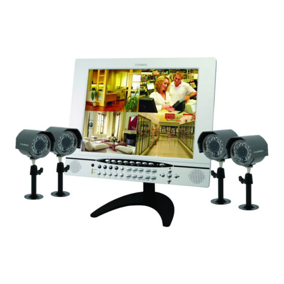
15" lcd color observation system with built-in 4 channel triplex digital video recorder and 4 night vision ccd cameras
Hide thumbs
Also See for L15LD400 series:
- Quick start manual (12 pages) ,
- Quick start manual (12 pages) ,
- Instruction manual (37 pages)
Table of Contents

Related Manuals for Lorex L15LD400 series


Summary of Contents for Lorex L15LD400 series
-
Page 1: Instruction Manual
15" LCD COLOR OBSERVATION SYSTEM With Built-In 4 Channel Triplex Digital Video Recorder and 4 Night Vision CCD Cameras Instruction Manual English Version 1.0 MODEL: L15LD400 Series www.lorexcctv.com © Copyright 2007 LOREX Technology Inc. - Page 2 Thank you for purchasing the L15LD400 Series Observation System. Lorex is committed to providing our customers with a high quality, reliable security product. The L15LD400 Series observation system is one of the most sophisticated video security systems on the market today with many of the same advanced features you will find in “high security”...
-
Page 3: Important Safeguards
Important Safeguards Important Safeguards In addition to the careful attention devoted to quality standards in the manufacture process of your video product, safety is a major factor in the design of every instrument. However, safety is your responsibility too. This sheet lists important information that will help to assure your enjoyment and proper use of the video product and accessory equipment. - Page 4 Important Safeguards Service 13. Servicing - Do not attempt to service this video 19. Cleaning - Unplug the video product from the wall equipment yourself as opening or removing covers outlet before cleaning. Do not use liquid cleaners or may expose you to dangerous voltage or other aerosol cleaners.
- Page 5 4. Keep enough space around the unit for ventilation. Slots and openings in the storage cabinet should not be blocked 5. During lightning storms, or when the unit is not used for a long time, disconnect the power supply, antenna, and cables to protect the unit from electrical surge LOREX TECHNOLOGY INC. http://www.lorexcctv.com...
- Page 6 • Commercial grade monitor stand • Wall or Rack mountable (mounts sold separately) • A full range of LOREX Pro Series CCTV cameras available for use with this system Built-In Digital Video Recorder (DVR) • Triplex Technology allows for recording, playback or viewing simultaneously.
-
Page 7: Table Of Contents
Table of Contents Table of Contents Getting Started ..................9 L15LD400 Series - Front ..............10 - 12 L15LD400 Series - Side ................13 L15LD400 Series - Back ................. 14 Remote Control ..................15 MC7521 Cameras ................... 16 Camera Installation ................17 - 19 Installation Warnings: ........................ - Page 8 Table of Contents Configuration ..................37 - 40 HDD MANAGEMENT ........................ 37 CAMERA SETUP ........................38 MOTION SETUP ........................38 ALARM SETUP ......................... 39 INTERVAL SETUP ........................39 TIME/DATE SETUP ........................40 PASSWORD SETUP ......................... 40 BUZZER SETUP ........................40 EXTERNAL DEVICE ................
-
Page 9: Getting Started
Getting Started Getting Started The SG19LD804-161 comes with the following components: LCD & DVR COMBO UNIT 4 x CAMERAS WITH INSTALLED 160 GB HDD 4 x METAL STANDS 1 x POWER ADAPToR 4 x 60 FT. (18M) 1 x 4-SPLITTER CAMERA EXTENSION CABLES POWER ADAPTOR 1 x 10’... -
Page 10: L15Ld400 Series - Front
L15LD400 Series - Front L15LD400 Series - Front 1. DISPLAY CONTROL BUTTONS - Control the onscreen display of Cameras: • SEQ - Displays cameras 1~4 in Full Screen Sequencing Mode • PIP - Displays cameras in Picture in Picture mode. The displayed cameras can be set by selecting either the main screen or PIP screen, and selecting a number 1~4. - Page 11 L15LD400 Series - Front L15LD400 Series - Front 7. IR RECEIVER & LED INDICATORS: • IR RECEIVER - Receiver for the Remote Controller signal. • DVR STATUS LEDs: POWER - Power LED indicator for the System power status (ON/OFF). HDD - HDD access LED indicated when activity is taking place on the system Hard drive. 8.
- Page 12 L15LD400 Series - Front L15LD400 Series - Front 10. PLAYBACK CONTROLS: • BACK – Reverses the playback. • STOP - Stops the playback. • PAUSE – Pauses the playback. • PLAY - Plays back the recorded data. • REW - Fast Rewind of the playback •...
-
Page 13: L15Ld400 Series - Side
L15LD400 Series - Side L15LD400 Series - Side 1. REMOVABLE DRIVE BAY - Drive bay to install a removable Hard Drive. 2. DRIVE BAY LOCK - Locking mechanism for the removable drive. 3. USB BACKUP PORT - Connect a USB memory stick or USB HDD for data backup 4. -
Page 14: L15Ld400 Series - Back
L15LD400 Series - Back L15LD400 Series - Back 1. ALARM BLOCK CHART - Outlines the Alarm Block connections 2. RS-232C - Connection port to the PC or for other DVR control devices 3. ALARM BLOCK & RS485 CONNECTIONS - Controls Alarm devices, and for direct connection to PTZ cameras. -
Page 15: Remote Control
Remote Control Remote Control Listed below is a quick reference for the Remote Control. MENU BUTTON - PIP - Opens the Main Menu Changes the display to (system setup) Picture in Picture mode SEQUENCE - P/T - Turns camera Controls Sequence Mode ON/ Camera (not included). -
Page 16: Mc7521 Cameras
MC7521 Cameras MC7521 Cameras The System includes 4 CCD Color IR Day/Night Indoor/Outdoor Cameras* INFRA-RED LEDs - Provides illumination for low light conditions CAMERA LENS STAND - Stand connects Camera for mounting to walls, ceilings and other surfaces INPUT CABLE - BNC Sends Video to the System INPUT CABLE - POWER Provides power for the... -
Page 17: Camera Installation
Camera Installation Camera Installation Before you install the camera, carefully plan where and how you will position the camera, and where you will route the cable that connects the camera to the System. Installation Warnings: • Select a location for the camera that provides a clear view of the area you want to monitor, which is free from dust, and is not in line-of-sight to a strong light source or direct sunlight. -
Page 18: Connecting Cameras
Camera Installation Connecting Cameras 1. Connect the Female BNC end of the supplied 60’ extension’ cable to the camera. Connect the male Power end of the extension cable to the camera. IMPORTANT NOTE: The ends of the extension cable are NOT the same - one end has a Male power port, and the other has a Female power port. -
Page 19: Camera Installation
Camera Installation 2. Connect the Female end of the supplied 60’ extension cable to an open BNC camera input on the back of the System. Connect the female Power end of the extension cable to the 4-cable power adaptor. NOTE: To access the Connection Ports for the System, the monitor can be tilted forward (for easier access). -
Page 20: Connecting The Mouse
Connecting the Mouse Connecting the Mouse Connect the supplied mouse to the PS/2 Port on the back of the unit. Alternatively, a mouse can be connected to the USB port located on the side of the unit. USB Connection - A mouse can be connected to the PS/2 Port on the back of the unit. -
Page 21: Display Modes
Display Modes Display Modes Initial Loading Sequence • Connect the POWER cable located on the back of the Observation System. The unit will automatically power on. • The System will load the firmware • The System will perform a Hard Drive check. •... -
Page 22: Network Status Indicators
Display Modes Network Status Indicators The Network Indicators appear when a remote connection is made to the unit: • Indicates that there is no client connection. • Indicates that a client is connected to the system. Recording Mode Indicators The Recording Mode Indicators appear in YELLOW when a camera is recording: •... -
Page 23: Display Modes
Display Modes Display Modes Cameras can be displayed in Single, Quad, Sequence or PIP modes by pressing the buttons on the front panel of the System, or by using the mouse to click on the onscreen icons. Accessing the Onscreen Setup Menu To access the onscreen Setup menu: •... -
Page 24: Sequence Display Mode
Display Modes Sequence Display Mode Displays cameras in sequence. Press the SEQ Button on the front panel of the System, or use the mouse to select the onscreen sequence icon. Press the SEQ Button on the front panel. Select Sequence mode by using the mouse to select the sequence icon. -
Page 25: Zoom Mode
Display Modes Zoom Mode Displays a single camera in ZOOM Mode (200% Zoom). Select the channel to ZOOM, and press the ZOOM button on the front panel of the System, or use the mouse to select the onscreen ZOOM icon. The area of ZOOM can be moved using the front panel arrows, or by using the Mouse. -
Page 26: Recording Mode
Recording Mode Recording Mode RECORDING MODE: • Indicates that the camera is recording in ALARM Mode. • Indicates that the camera is recording in MOTION DETECTION Mode. • Indicates that the camera is recording in CONTINUOUS Mode. HDD STATUS The HDD Status bar indicates the total hard drive amount, and the amount of drive space currently in use. -
Page 27: Recording Mode
Recording Mode Recording Mode RECORDING STATUS • Red Icon: Indicates the system is recording in Schedule, Motion or Alarm Mode. • White Icon: Indicates that the record schedule is not set to record. If the unit loses power, recording will automatically resume once power is restored (based on the recording schedule setup). -
Page 28: Playback
Playback Playback Starting Playback Mode Press the PLAY button on the front panel of the System, or click the onscreen PLAY icon to start playback, starting from the most recent recording. -
Page 29: Stopping Playback Mode
Playback Stopping Playback Mode Press the STOP button on the front panel of the System, or click the onscreen STOP icon to stop the playback. Search Mode Press the SEARCH button on the front panel of the System, or click the onscreen SEARCH icon to search through previously recorded data. -
Page 30: Percent Search
Playback Percent Search • Use the Mouse wheel to select the recording percentage on the search bar. • Click “PLAY” to confirm and start the playback. Time/Date Search • START - Set the start time and date for the recording. •... -
Page 31: Event Search
Playback Event Search • TIME/DATE - Displays the event time and date. • CHANNEL - Displays the channel in which the event occurred. • EVENT - Displays the event type: MOT - Motion detection LOS - Image lost ALM- Alarm trigger The system keeps up to 1000 events in its EVENT LIST. - Page 32 Playback The playback speed can also be adjusted using the Front Panel buttons or Remote Control: While in playback mode, use the direction keys on the remote control to adjust the speed: X times high-speed playback. X times low speed playback. Rewind.
-
Page 33: System Setup And Navigation
System Setup and Navigation System Setup and Navigation Press the MENU button on the Front panel or Remote, or click the onscreen MENU icon to log into system: • Click the 0~9 icons (or use the front panel buttons) to enter the password. -
Page 34: Display Setup - Screen Setup
System Setup and Navigation Display Setup - Screen Setup 1. VERTICAL POSITION - Adjust the vertical position of the image. 2. HORIZONTAL POSITION - Adjust the horizontal position of the image. 3. BORDER ENABLE - Enable the display of border. 4. -
Page 35: Record Setup
Record Setup Record Setup 1. RECORD SETUP - Set up recording mode, resolution, picture quality, and recording frame rate. 2. SCHEDULE SETUP - Program the recording schedule. Record Setup - Record Configuration 1. CHANNEL - Select a Channel to configure. 2. -
Page 36: Record Setup - Schedule Setup
Record Setup Record Setup - Schedule Setup 1. CHANNEL - Select a single channel to setup the schedule. 2. TYPE - Select a recording mode: • Continuous Recording: Recording constantly occurring. • Motion: Begins the recording when motion is detected. •... -
Page 37: Configuration
Configuration Configuration 1. HDD MANAGEMENT - Includes HDD SETUP (HDD Clear), and HDD INFORMATION. 2. CAMERA SETUP - Includes CAMERA TITLE and CAMERA COLOR SETUP. 3. MOTION SETUP - Includes SENSITIVITY, DURATION, DETECT CELL NUMBER. 4. ALARM SETUP - Set up the Alarm mode (N.C. or N.O) and the Alarm Output Duration. -
Page 38: Camera Setup
Configuration CAMERA SETUP 1. CHANNEL - Select the camera to be modified. 2. TITLE - Input the camera Title, max. 8 characters. 3. BRIGHTNESS - Adjust image brightness (-32~31). 4. CONTRAST - Adjust color contrast (-32~31). 5. SATURATION - Adjust color saturation (-32~31). 6. -
Page 39: Alarm Setup
Configuration ALARM SETUP 1. CHANNEL - Select a channel for the setup. 2. ALARM INPUT - Set up the Alarm Input type. • NORMALLY CLOSED - The Alarm is triggered when the circuit is closed (ON). • NORMALLY OPEN - The Alarm is triggered when the circuit is opened (OFF). -
Page 40: Time/Date Setup
Configuration TIME/DATE SETUP The date and time set by the manufacturer may be different from your time zone. It is very important to configure the system date and time before starting recording. Set the date and time by using Mouse wheel: •... -
Page 41: External Device
EXTERNAL DEVICE EXTERNAL DEVICE 1. TCP/IP SETUP - Configure the system Networking information. 2. PAN/TILT SETUP - Set up the parameters of the PTZ control. 3. SPOT SETUP - SPOT output setup. 4. RS232C SETUP - Set up the parameters of the RS232 port. -
Page 42: Tcp/Ip Setup - Speed
EXTERNAL DEVICE 3. INTERVAL - Set the interval for the system to report its IP address to the DDNS server automatically. (D- day / H- hour / M- minute). Use the Mouse Wheel to change the value. 4. REGISTER - Connect to the DDNS server and register the system information to the server. -
Page 43: Pan/Tilt Setup - Speed Setup
EXTERNAL DEVICE PAN/TILT SETUP - SPEED SETUP 1. PAN SPEED - Set the PANing speed (0 low ~ 7 high). 2. TILT SPEED - Set the TILTing speed (0 low ~ 7 high). 3. ZOOM SPEED - Set the speed of ZOOM IN/OUT (0 low ~ 7 high). -
Page 44: Rs232C Setup
BACKUP RS232C SETUP Users can connect the System to a PC through the RS232 port. Other system control devices can also be connected through the RS232 port. The ASCII-Code information is in Serial port setup (Users cannot change value in this setting). 1. -
Page 45: Data Backup
Data Backup Data Backup System status messages: • USB STATUS - Insert USB Key - the system will check the available space. When choosing a backup size, leave 20MB as a buffer and do not use the full space of the USB Stick. -
Page 46: Troubleshooting
When a malfunction occurs, it may not be serious and can be corrected easily. The following describes the most common problems and solutions. Please refer to the following before calling Lorex Technical Support: Problem: Observation System Unit is not receiving power, or is not powering up Check: •... -
Page 47: Observation System Specifications - Appendix #1
Observation System Specifications - Appendix #1 Observation System Specifications - Appendix #1 Monitor Specifications LCD Panel Diagonal: 15.0” TFT, Input: TTL / LVDS. LCD Display Resolution 1280 x 1024 Video Input 4CH (4 x BNC) Video Output Monitor / Spot (BNC x 1) Split Screen Full screen, Quad split Zoom... -
Page 48: Mc7521 Camera Specifications - Appendix #2
Weather Proof Rating IP64 Operating Humidity 90% RH max. As our products are subject to continuous improvement, LOREX Technology Inc. and its subsidiaries reserve the right to modify product design, specifications and prices, without notice and without incurring any obligation. E&OE... -
Page 49: Full Connectivity Diagram - Appendix #3
Full Connectivity Diagram - Appendix #3 Full Connectivity Diagram - Appendix #3 The following diagram outlines a general set of connections available with the Observation System. ROUTER (Not Included) (Not Included) OBSERVATION SYSTEM SENSOR 4 x 1/4” CCD CAMERAS SLAVE / SPOT OUT (Not Included) (Included) MONITOR... -
Page 50: Connecting A Slave (Spot-Out) Monitor - Appendix #4
Connecting a Slave (Spot-Out) Monitor - Appendix #4 Connecting a Slave (Spot-Out) Monitor - Appendix #4 Connections to a Slave Monitor / Spot-Out Monitor (not included with the System) can be made through the VIDEO OUT and/or the SPOT OUT ports on the back of the Observation System. A slave monitor can be a TV or Computer Monitor with VGA inputs. -
Page 51: Connecting Motion / Alarm Device - Appendix #5
Connecting Motion / Alarm Device - Appendix #5 Connecting Motion / Alarm Device - Appendix #5 Motion detection and Alarm controls are enabled through the Menu system on the Observation System. Additional motion sensor devices can be connected to the system (Motion Sensors, Door/Window Sensors). -
Page 52: Connecting Ptz Cameras - Appendix #6
Connecting PTZ Cameras - Appendix #6 Connecting PTZ Cameras - Appendix #6 PTZ Cameras (not included with this system) can be connected to the PTZ Control Block on the back panel of the System. The PTZ Controls are enabled through the Menu system on the Observation System. -
Page 53: Connecting To A Pc Using The Serial Port - Appendix #7
Connecting to a PC using the Serial Port - Appendix #7 Connecting to a PC using the Serial Port - Appendix #7 The Observation System can be connected directly to a PC COM Port by using the Serial Port located on the back of the system. •... -
Page 54: Hard Drive Replacement - Appendix #8
Hard Drive Replacement - Appendix #8 Hard Drive Replacement - Appendix #8 The Hard Drive serves the same purpose in an Observation System as a video cassette does in a VCR. Please follow the steps carefully in order to ensure proper installation. The compartment located on the front panel of the DVR is the removable Cartridge Casing in which you insert the Hard Drive. - Page 55 Hard Drive Replacement - Appendix #8 STEP 4: Secure the Hard Drive in the Casing • Use screws and tighten them, positioning the Hard Drive into place. This step is optional, but it is recommended. Position Hard Drive and secure with provided screws STEP 5: Slide the top Cover over the Cartridge Casing •...
-
Page 56: Optional Accessories
Optional Accessories Optional Accessories The following accessories are available to add to your existing system: SLAVE / SPOT OUT BNC TYPE EXTENSION MONITOR CAMERAS CABLE Slave / Spot Out Monitors - Additional BNC Type Extends the length View selected Cameras on a Cameras between the CAMERA second Monitor... - Page 57 LOREX neither assumes nor authorizes any person to assume for it any other obligation or liability in correction with the sale or service of the Product. In no event shall LOREX be liable for any special or consequential damages arising from the use of the Product or arising from the malfunctioning or non-functioning of the Product, or for any delay in the performance of this warranty due to any cause beyond its control.
- Page 58 It’s all on the web Product Information Specification Sheets User Manuals Software Upgrades Quick Start Guides Firmware Upgrades VISIT www.lorexcctv.com wwwlorexcctv.com Lorex Technology Inc.