Lorex L14Q684C User Manual
Ip enabled 14” 2 page / 8 channel color quad observation system with 4 night vision cameras
Hide thumbs
Also See for L14Q684C:
- Network configuration manual (12 pages) ,
- Setup manual (5 pages) ,
- Network setup manual (13 pages)
Table of Contents

Related Manuals for Lorex L14Q684C


Summary of Contents for Lorex L14Q684C
- Page 1 IP ENABLED 14” 2 PAGE / 8 CHANNEL COLOR QUAD OBSERVATION SYSTEM WITH 4 NIGHT VISION CAMERAS L14Q684C FOR MORE INFORMATION WWW.LOREXCCTV.COM BEFORE OPERATING THIS SYSTEM, PLEASE READ THIS MANUAL THOROUGHLY AND RETAIN IT FOR FUTURE REFERENCE...
- Page 2 Thank you for purchasing the IP enabled 14” 2 Page/8 Channel Color Quad Observation system. Lorex is committed to providing our customers with a high quality, reliable security product that customers have come to expect from us. The IP enabled Observation system allows you to make an ethernet LAN connection from the monitor to a computer for internet monitoring.
- Page 3 • Increase the separation between the camera and the monitor. • Connect the equipment into an outlet on a circuit different from that to which other electrical devices are connected. • Consult the dealer or an experienced radio or television technician for help. Lorex Technology Inc.. www.lorexcctv.com -ii-...
-
Page 4: Table Of Contents
17. APPENDIX C - CONNECTING TO A SLAVE MONITOR ----------------------------- 18. APPENDIX D – TYPICAL CONFIGURATION ------------------------------------------- 19. APPENDIX E - CONNECTING TO A LOREX TIME LAPSE VCR FOR ALARM RECORDING ------------------------------------------------------------------- 20. APPENDIX F – CONNECTING TO A LOREX SINGLE CHANNEL DVR ---------- 21. CARE AND MAINTENANCE ------------------------------------------------------------------... -
Page 5: General Precautions
GENERAL PRECAUTIONS: Read Instructions All of the safety and operating instructions should be read and understood before the product is used. Retain Instructions The safety and operating instructions should be retained for future reference. Heed Warnings All warnings on the product and the instruction manual should be followed. -
Page 6: Cautions And Features
CAUTIONS: 1. All the warnings and instructions of this manual should be followed 2. Remove the plug from the outlet before cleaning. Do not use liquid aerosol detergents. Use water damped cloth for cleaning 3. Do not use this unit in very humid and wet places 4. -
Page 7: System
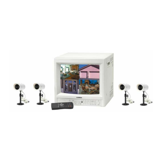
SYSTEM INCLUDES: CH1/5 CH2/6 CH3/7 CH4/8 QUAD1/2 ENTER ALRS VOLUME 14” COLOR 2 PAGE / 8 CHANNEL QUAD MONITOR ALSO INCLUDES, IP SOFTWARE & LAN CABLE Please refer to the Quick Start Guide and CD for the Owner’s Manual (IP Server software) Note: This software must be installed on a PC before connecting the LAN... -
Page 8: Monitor Controls - Front Panel
CONTROL - FRONT PANEL: 1. Channel 1/5 – Channel 4/8 - These buttons perform the following functions: a) Displays a picture in Full Screen. If you are in the Quad1 mode, select the Channel 1/5 button and hold for 2-3 seconds to view Camera 1 in Full Screen. To view other camera locations, press Ch 2/6, Ch 3/7, Ch 4/8 buttons. - Page 9 5. Menu / (Pan/Tilt) - This button serves 2 functions: a) Menu – Press this button to enter the menu option screen. For more information on Menu mode, please refer to page 8. b) Pan/Tilt – This button activates the Pan/Tilt feature. For more information on the Pan/Tilt Zoom feature please refer to page 10.
- Page 10 Main - Pressing the Main button while viewing PIP/Dual PIP/POP mode will change the camera location of the main screen being displayed. Sub1 & Sub2 - Pressing the Sub1/Sub2 buttons in PIP mode changes one of the two camera locations being displayed as a picture in picture. These buttons will also remove / add a sub-picture to create a Single PIP / Dual PIP viewing mode.
-
Page 11: Main Menu Control
MAIN MENU CONTROL Enter the Menu screen by pressing the Menu button. Scroll through the eight options by pressing the UP and DOWN buttons. To enter a sub-menu, press the Enter button where the highlighted scroll bar is located. To exit the Main Menu, scroll down to the Exit option and press Enter. - Page 12 4. Title Set – This submenu allows you to change the title of each camera location (up to 8 characters), or remove the titles from the on-screen display. DISPLAY: Selecting [Y] will enable the camera titles to appear in the on-screen display. Selecting [N] will remove all titles from appearing in the on-screen display.
-
Page 13: Pan/Tilt Zoom
PAN / TILT ZOOM: The monitor is equipped with a built-in Pan/Tilt Zoom feature, which is only available when used in conjunction with a compatible Lorex Pan/Tilt Zoom (Zoom optional) Dome camera. (model SG7380) Please refer to www.lorexcctv.com for more information on the available accessories (sold separately). - Page 14 You will see a contracted screen with a blue border. Use the Arrow keys to sideways, and ENTER to select whether to MOVE, ZOOM, or FOCUS the camera. (note: Focusing is currently not available on the SG7380 Dome camera). Enter Pan/Tilt Zoom mode by holding the PAN/TILT key on the monitor for 3 seconds, or press the Pan/Tilt button on the remote control;...
-
Page 15: Monitor Controls - Back Panel
MONITOR CONTROLS - BACK PANEL: 1. Power Switch – This button controls power to the entire unit. Depress the side with the ”•” to turn power ON. Depress the other side to turn the unit OFF 2. Ethernet Input – Connect the LAN cable for IP enablement to a computer (see the Software CD and Quick Start Guide for further instructions) 3. -
Page 16: Remote Control
REMOTE CONTROL: Features of the Remote Control. For more details on specific remote control features, refer to the Monitor features FUNCTION DESCRIPTION Turns Power to unit On/Off. MUTE Cuts off the sound from the camera. AUDIO SEL Selects the Audio channel in Quad mode ▲... -
Page 17: Standard Wired Camera
STANDARD WIRED CAMERA: Camera Lens – Delivers high quality image by using a 1/3” CMOS Image Sensor LED’s - 6 Blue LED’s for day/night vision Speaker – Delivers sound from the monitor to the camera Camera Input – Connect cable to monitor Bracket –... -
Page 18: Monitor Connections
MONITOR CONNECTIONS: VIDEO AUDIO DC12V CAMERA TROUBLE SHOOTING: If the system does not function properly, please check the following points. PROBLEM MONITOR Too dark or bright picture NO POWER Poor picture quality Picture but no sound Shrinking picture WIRED No Picture CAMERA Picture Flickering or Over Exposed... -
Page 19: Technical Specifications
TECHNICAL SPECIFICATIONS: MONITOR Picture Tube Resolution Camera Capable Quad Speed Camera Input Alarm Inputs/Outputs Input signal Power Source Power Consumption Operating Temperature Weight Dimensions: STANDARD CAMERA Image Device Resolution Shutter control Power requirement Illumination Operating Temperature Weight: Dimensions: Housings: As our products are subject to continuous improvement, SVII and its subsidiaries reserve the right to modify product design, specifications and prices, without notice and without incurring any obligation. -
Page 20: Optional Accessories
OPTIONAL ACCESSORIES The following accessories are available to add to your existing system. CABLE Extends viewing length from Camera to monitor. Available In 65, 100 and 250 ft lengths OBSERVATION CAMERAS Accessory PIR motion sensor observation system camera TO ORDER THESE ACCESSORY ITEMS OR FOR A COMPLETE LINE OF ACCESSORIES TIME LAPSE VCR Used to record key events. -
Page 21: Appendix A - Connecting Monitor To Astandard Vcr
APPENDIX - A CONNECTING MONITOR TO A STANDARD VCR: PLEASE SEE THE DIAGRAM BELOW FOR CONNECTING YOUR VCR TO THE MONITOR. NOTE: Ensure the Standard VCR’s channel is set to A/V Mode in order to ensure reception. Consult your VCR’s Owners Manual to set the VCR to this setting. •... -
Page 22: Appendix B -Connecting Monitor To A Dvr
APPENDIX - B CONNECTING MONITOR TO A DVR: PLEASE SEE THE DIAGRAM BELOW FOR CONNECTING YOUR DVR TO THE MONITOR FOR RECORDING PURPOSES. NOTE When recording to a Digital Video Recorder, the DVR may indicate a Video Loss as the monitor sequences between channels. -
Page 23: Appendix C - Connecting To A Slave Monitor
APPENDIX - C CONNECTING TO A SLAVE MONITOR: Connections to another monitor (e.g. Slave Monitor) can be made through “SLAVE OUT” as show in the diagram below. MONITOR -20-... -
Page 24: Appendix D - Typical Configuration
APPENDIX - D TYPICAL CONFIGURATION FOR COMPLETE SYSTEM: COMPUTER SENSOR CAMERA MONITOR -21-... -
Page 25: Appendix E - Connecting To A Lorex Time Lapse Vcr For Alarm Recording
APPENDIX - E CONNECTING TO A LOREX TIME LAPSE VCR FOR ALARM RECORDING -22-... -
Page 26: Appendix F - Connecting To A Lorex Single Channel Dvr
APPENDIX - F CONNECTING TO A SINGLE CHANNEL DIGITAL VIDEO RECORDER FOR ALARM RECORDING Alarm Block NO 8 15 COM 14 A/I NC 7 R/S 6 13 A/R E/O 5 12 D/F S/O 4 11 RX2 10 TX2 V/L 3 9 GND TX1 2 RX1 1... -
Page 27: Care And Maintenance
CARE AND MAINTENANCE: Please follow the following instructions to ensure proper care and maintenance of this system Keep your monitor and camera dry. If it gets wet, wipe it dry immediately. Use and store your unit in normal temperature environment. Extreme temperatures can shorten the life of the electronic devices.