
Related Manuals for Echo Layla24


Summary of Contents for Echo Layla24
- Page 1 ® ® LapTop LAYLA LAYLA ® GINA ™ ™ MIAMIDI Owner’s Manual Version 3.1.1 for Windows...
-
Page 2: Important Safety Instructions
Important Safety Instructions 1. Read Instructions - Be sure to read all of the safety and operating instructions before operating this product. 2. Retain Instructions - The safety instructions and owner's manual should be retained for future reference. 3. Heed Warnings - All warnings on your Echo product and in the Owner's Manual should be followed. - Page 3 11. Damage Requiring Service - Unplug this unit and refer it to a qualified service technician when any of the following occur: a) Objects have fallen or liquid has spilled into the unit b) The product has been exposed to rain or water c) The product does not operate normally or when a marked change in performance is noticed d) The product has been dropped or damaged in any way...
-
Page 4: Limited Warranty
Sending in your registration card – or registering online at http://www.echoaudio.com/support/register.php allows us to register key information so that we may handle problems faster and inform you of advance information on upgrades and other news. Thanks in advance for filling out your registration card and sending it to us. We hope you enjoy your Echo product. - Page 5 ©2003 by Echo Digital Audio Corporation 6450 Via Real Suite 1 Carpinteria, CA 93013 ® ® ® ® Echo , Layla 24, Layla LapTop , Gina 24, Mia™, and MiaMIDI™ are trademarks of Echo Digital Audio Corporation. ® ADAT is a registered trademark of Alesis Corporation. ®...
-
Page 6: Table Of Contents
INTRODUCTION....................9 ..........10 HOULD ECEIVED IN THE ..................11 YSTEM EQUIREMENTS INSTALLATION ....................12 ....................12 YSTEM OUNDS . WDM - D ........12 ECIDING HICH RIVER TO NSTALL PCI C ........13 NSTALLING THE ARD FOR ESKTOP OMPUTERS ...... - Page 7 ................... 51 ONSOLE ONTROLS ..................51 ONITOR ONTROLS ..................... 53 UTPUT ONTROLS ........... 53 DJUSTING ONITOR AND LAYBACK EVELS ........... 54 ETTING LOCK OURCES AND ESTINATIONS ..............55 YNCHRONIZING ULTIPLE EVICES ....................58 ..................59 REFERENCES I/O - S S/PDIF O ........
- Page 8 APPENDIX D: WDM-WINDOWS DRIVER MODEL FAQ......93 APPENDIX E: AN INTRODUCTION TO DIGITAL RECORDING ... 97 APPENDIX F: SPECIFICATIONS ..............103...
-
Page 9: Introduction
Introduction – all products Introduction Thank you for choosing Echo Digital Audio. We think you’ll find your Echo product to be an extremely flexible, high-performance tool for your computer- based hard disk recording system. Introduction – all products... -
Page 10: What You Should Have Received In The Box
Introduction – all products What You Should Have Received in the Box When you opened the box, you should have found the following: • A PCI card wrapped in an anti-static cover OR a CardBus Adapter • An audio interface box (Layla24 and Gina24 only) •... -
Page 11: System Requirements
Introduction – all products System Requirements In order to use Layla24, Gina24, Mia or MiaMIDI you’ll need the following: • A desktop computer with one of the following: • A genuine Intel Pentium processor and genuine Intel chipset OR • An AMD Athlon or Duron processor •... -
Page 12: Installation
Installation – all products Installation Complete installation consists of disabling Windows system sounds, deciding which Echo driver you are going to use, installing the Windows drivers into your system, installing the PCI or CardBus card, connecting the audio interface to the card (Layla24 and Gina24) and, if necessary, installing a multitrack audio recording/editing application. -
Page 13: Installing The Pci Card For Desktop Computers
Installation – all products 2) You are using an audio program that uses an ASIO driver. In general, the WDM ASIO driver provides higher performance than the VxD ASIO driver. For a detailed discussion of the benefits and drawbacks of the WDM architecture, please read Appendix F: WDM-Windows Driver Model FAQ. - Page 14 Installation – all products or, more simply, by touching your bare hand to the metal casing of the computer’s power supply. (For this latter method to work, the computer must be plugged in, though not turned on.) After you’ve discharged your static, unplug the computer before proceeding to the next step.
- Page 15 Installation – all products of the cable to the connector on the rear of the interface labeled computer and fasten the cable securely with the screws. Plug the power cable firmly into the interface and a power socket, but do not turn on the interface at this time (Layla24 only).
-
Page 16: Installing The Cardbus Adapter For Laptop Computers
Installation – all products Installing the CardBus Adapter for Laptop Computers Once you have verified that there are no problems with your system, it is time to install Layla24 LapTop into your laptop computer. 1. Install the drivers. You should do this before inserting the CardBus Adapter. Insert the Echo Install CD-ROM into your machine. - Page 17 Installation – all products Note: this version of the WDM driver has not been digitally signed by Microsoft; for Windows 2000 and XP, you will need to confirm that you want to install an unsigned driver. Once the driver is installed, a small “PCCard” icon will appear in the system “tray” (usually on the lower right-hand side of the screen).
-
Page 18: Connecting To Layla24'S Rack-Mount Audio Interface
Audio connections – Layla24 Connecting to Layla24’s Rack-mount Audio Interface The back panel of Layla24’s rack-mount audio interface contains a wide variety of connections that allow great flexibility in the operation of Layla24. For optimal performance with Layla24, it is critical to use the appropriate cabling and connectors. - Page 19 Audio connections – Layla24 The Computer Connector Next to the analog inputs and outputs is a connector labeled COMPUTER. This connector is known as a DB-9, and is similar to the serial port on a PC. It is the point at which the audio interface connects to the Layla24 PCI card inside your computer.
- Page 20 Audio connections – Layla24 S/PDIF Next to the ADAT connectors is a pair of connectors labeled S/PDIF, IN and OUT. These S/PDIF connectors are used to transmit digital audio data between digital audio devices via an electrical signal. S/PDIF data can use the full 24-bit sample width used internally on Layla24.
- Page 21 Audio connections – Layla24 MIDI The last set of connections to the Layla24 interface is for MIDI. The MIDI ports can be used for receiving MIDI time code (MTC), or sending and receiving MIDI signals between your digital audio/MIDI sequencing software and external sound modules, etc.
-
Page 22: Connecting To Gina24'S Audio Interface
Audio connections – Gina24 Connecting to Gina24’s Audio Interface The front and back panels of Gina24’s audio interface contain a wide variety of connections that allow great flexibility in the operation of Gina24. To achieve the optimal performance with Gina24, it is critical that the appropriate cabling and connectors are used. - Page 23 Audio connections – Gina24 A cable was supplied with your Gina24 for this purpose. This custom made cable is manufactured to certain specifications; if you need to replace it, you should only use a replacement cable from Echo. Please Note: The Gina24 cable is NOT interchangeable with Darla24 or Gina (20-bit) cables.
- Page 24 Audio connections – Gina24 S/PDIF Next to the ADAT connectors is a pair of connectors labeled S/PDIF, IN and OUT. These S/PDIF connectors are used to transmit digital audio data between digital audio devices via an electrical signal. S/PDIF data can use the full 24-bit sample width used internally on Gina24.
-
Page 25: Connecting To Mia
Audio connections – Mia Connecting to Mia Analog Inputs and Outputs Mia has two analog outputs (OUT1 and OUT2) and two analog inputs (IN1 and IN2) on the back. The input and output connections can accept balanced or unbalanced jacks via ¼” connectors. By default, both the inputs and outputs are set to receive or send a +4 dBu signal. - Page 26 Audio Connections – Mia When connecting devices to the S/PDIF jacks on Mia, the use of standard analog RCA audio cables is not recommended. For reliable S/PDIF operation, 75ohm coaxial (RG59) video cables are recommended. Audio Connections – Mia...
-
Page 27: Connecting To Miamidi
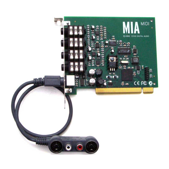
Audio Connections – MiaMIDI Connecting to MiaMIDI Analog Inputs and Outputs MiaMIDI has two analog outputs (OUT1 and OUT2) and two analog inputs (IN1 and IN2) on the back. The input and output connections can accept balanced or unbalanced jacks via ¼” connectors. - Page 28 Audio Connections – MiaMIDI MIDI-S/PDIF Breakout Cable To connect MIDI or S/PDIF signals to MiaMIDI, you will need to first connect the breakout cable. The breakout cable looks like this: MIDI and S/PDIF inputs are on the left side, just under the label “IN”. Outputs are, obviously, on the right.
-
Page 29: Using Audio Software
Audio Software – Gina24 and Layla24 Using Audio Software Gina24 and Layla24 To audio software, the Echo hardware appears as a group of stereo wave devices. You can view the list of these devices either from within your audio software or from the Windows control panel. - Page 30 Audio Software – Gina24 and Layla24 And for recording: Win98/WinMe (VxD) Win2000/WinXP (WDM) Layla24 1/2 Analog Record Layla24 1/2 Analog In Layla24 3/4 Analog Record Layla24 3/4 Analog In Layla24 5/6 Analog Record Layla24 5/6 Analog In Layla24 7/8 Analog Record Layla24 7/8 Analog In Layla24 S/PDIF Record Layla24 1/2 Digital In...
- Page 31 Audio Software – Gina24 and Layla24 The WDM drivers work a little differently, depending on the current digital mode. Gina24 and Layla24 have a digital mode switch that lets you set how the hardware transmits and receives digital audio signals. The digital mode switch can be set to S/PDIF RCA, S/PDIF optical, or ADAT optical.
-
Page 32: Mia And Miamidi
Using Audio Software – Mia and MiaMIDI Mia and MiaMIDI To audio software, the Mia and MiaMIDI hardware appears as a group of stereo wave devices. You can view the list of these devices either from within your audio software or from the Windows control panel. The items you see in the list will depend on what driver you installed: Win98/WinMe (VxD) WinMe/2000/WinXP (WDM) -
Page 33: Virtual Outputs - Mia And Miamidi
Virtual outputs – Mia and MiaMIDI Virtual Outputs - Mia and MiaMIDI Most audio cards with a pair of analog inputs and outputs will appear to software as having just that, a single pair of inputs and outputs. When one application appropriates the card for its use, all other software is “locked-out”... -
Page 34: Console3 (Wdm)
WDM console – all products Console3 (WDM) This section of the manual applies only if you installed the WDM drivers. A “virtual control surface” application called Console3 is included with the WDM driver. The Console allows you to control the audio I/O and clocking functions of your Echo product, and it brings these controls to a single easy-to-use location. - Page 35 WDM console – all products that output bus. Audio played through the selected channels by an application, any analog input, and any digital input may be mixed to an output bus. Screenshot of Layla24 Console3 main window - other Echo hardware will work similarly. WDM console –...
-
Page 36: Bus Select
WDM console – all products Bus select The bus select panel is the area outlined in green. Five different output busses are shown here: four analog busses in the top row and one digital bus on the bottom row. Each bus has its own button marked with either an A or D (Analog or Digital) and a channel number pair. -
Page 37: Analog Inputs
WDM console – all products on the other channel. Also, ganging the faders ties them together so they will maintain their relative placement with regard to each other. Holding down the Shift key reverses the state of the gang button; that is, if the gang button is down, holding down shift puts you in non-ganged mode and vice versa. -
Page 38: Digital Inputs
WDM console – all products Digital Inputs The controls for the digital inputs are outlined in light blue and have the label “Digital in” at the bottom. Their operation is identical to the analog input controls except the digital input controls don’t include a nominal level button. For Layla24 and Gina24, whether you are monitoring the S/PDIF or the ADAT inputs depends upon the digital mode you have selected. -
Page 39: Adjusting Playback Volume
WDM console – all products Adjusting Playback Volume Output volume adjustments are made in the digital domain. When you lower a volume fader below 0dB, you are actually decreasing the number of available bits, thereby taking away from the potential dynamic range of the system. Therefore, we suggest that whenever possible you leave the output faders set to 0dB, and perform any necessary attenuation on your external mixer. -
Page 40: Synchronizing Multiple Devices
WDM console – all products Synchronizing Multiple Devices Layla24, Gina24, Mia, and MiaMIDI are designed to work alongside other audio equipment. If you are planning on using your card with other audio equipment, please note the following: The Windows drivers included in this package support multiple Echo cards within the same system. - Page 41 WDM console – all products S/PDIF – The Sony/Phillips Digital Interchange Format is a serial bit-stream that has a clock signal embedded in the data stream. When recording from an S/PDIF source, whether via optical cables or RCA cables, Echo products will utilize the synchronization clock that is embedded in the S/PDIF while it decodes the bitstream.
- Page 42 WDM console – all products Now let’s take a look at some sample configurations and how you might set them up from a synchronization standpoint. Let’s start with a simple example. Suppose that Layla24 is the only audio device used in your system. Since you have no other devices to synchronize with, simply select Internal for Layla24’s input clock.
-
Page 43: Console Settings
WDM console – all products Console Settings Clicking the Settings button above the playback strips shows a dialog box for altering console settings. The Settings dialog gives you five different tabs to choose from: “Driver,” “Console,” “Digital I/O,” “GSIF,” and “About.” Driver Here you can do two things: lock the sample rate and tell the driver whether or not to synchronize wave devices. -
Page 44: Locking The Sample Rate
WDM console – all products Locking the sample rate Locking the sample rate can be very important, since Windows will frequently try to set the hardware to the highest rate it supports. Then, Windows sample rate converts between that rate and the rate at which you are playing or recording. For instance, you may be trying to play at 44.1 kHz, but Windows sets the hardware to 96 kHz and converts between the two. -
Page 45: Console Sessions
WDM console – all products Console Sessions Console settings can be saved as a console session to be reloaded later. To save a console session, click the “Save” button in the console. To load a previously saved session, press the Load button in the console. The current session can be “fast saved”... -
Page 46: Digital I/O
WDM console – all products Digital I/O This lets you set the format of your S/PDIF outputs. Your Echo card can transmit digital information in either of two formats: “professional” or “consumer.” The primary difference between the two is in the implementation of the SCMS copy protection bit, which, in the Consumer format, prevents the user from making digital copies of a digital copy. -
Page 47: Gsif
WDM console – all products GSIF This window allows you to set the latency of GigaStudio in terms of samples. Select the value here that provides the best tradeoff between performance and reliability. WDM console – all products... -
Page 48: About
WDM console – all products About This displays the console version and driver version numbers. We feel that this is the single most exciting feature on the new console. WDM console – all products... -
Page 49: Vxd Console - Gina24 And Layla24
VxD console – Gina24 and Layla24 VxD Console – Gina24 and Layla24 This section of the manual only applies if you installed the VxD drivers and are using Gina24 or Layla24. A “virtual control surface” application called the Console is included with the VxD driver. - Page 50 VxD console – Gina24 and Layla24 The console functions are grouped into three areas: inputs (in the upper left corner), monitors (directly below the inputs that are being monitored), and outputs (on the right hand side). The controls for a particular function/stereo pair are then further grouped into a box that contains selection buttons, faders, and other controls and displays as determined by the function.
-
Page 51: Console Controls
VxD console – Gina24 and Layla24 Console Controls Let’s take a look at the control surface. The input control area is located in the upper left portion of the console surface. For each input device pair you will find a pair of input meters. Each input also has a nominal level switch that switches between professional (+4 dBu) and consumer (–10 dBV) levels. - Page 52 VxD console – Gina24 and Layla24 Instead of level meters, each monitor control has a series of numbered buttons. These buttons allow you to select which output channel pair controls are displayed, so you can adjust them. The monitors are one of the most powerful functions of the console.
-
Page 53: Output Controls
VxD console – Gina24 and Layla24 Remember that all of the monitor controls remain in effect even when they’re not displayed. The degree of attenuation (or muting) of each level is set by the monitor controls. The console program constantly maintains a level setting for each of the monitor paths it controls. -
Page 54: Setting Clock Sources And Destinations
VxD console – Gina24 and Layla24 Setting Clock Sources and Destinations At the very bottom of the Console there are buttons that allow you to select the synchronization clocks. The console program will detect which input clocking options are available, and automatically disable those that are unavailable. Depending on what external devices you have connected, you may have as many as four out of five options available Layla24. -
Page 55: Synchronizing Multiple Devices
VxD console – Gina24 and Layla24 Synchronizing Multiple Devices Layla24, Gina24, Mia and Mia MIDI are designed to work alongside other audio equipment. If you are planning on using your Echo hardware with other audio equipment, please note the following: The Windows drivers included in this package support multiple Echo cards within the same system. - Page 56 VxD console – Gina24 and Layla24 Let’s take a brief look at the various synchronization types. Word Clock – This is a synchronization signal that connects to the BNC connector labeled Word Clock on Layla24’s back panel. This synchronization clock runs at the selected sample rate. Think of it as a kind of electronic metronome, which clicks back and forth at the digital sample rate.
- Page 57 VxD console – Gina24 and Layla24 Note: To preserve the high audio quality of Layla24/Gina24’s converters it is best to use the Internal input clock setting instead of synchronizing to an external ADAT clock, which may add unwanted jitter to the signal. Esync –...
-
Page 58: The File Menu
VxD console – Gina24 and Layla24 The File Menu At the top left of the Console window you will find the File menu. By selecting the File menu, several configuration options become available to you. The first menu option is “Preferences.” The Preferences option brings up the Console “Preferences Page”... -
Page 59: The Preferences Page
VxD console – Gina24 and Layla24 The Preferences Page The Preferences Page is accessible through the Console File menu. Digital I/O - Selecting the S/PDIF Output Format Your Echo hardware can transmit digital information in either of two formats, “professional” or “consumer.” The primary difference between the two is in the implementation of the SCMS copy protection bit, which, in the Consumer format, prevents the user from making digital copies of a digital copy. - Page 60 VxD console – Gina24 and Layla24 We have provided a software switch in the driver that allows you to select which format the Echo hardware transmits. In the window that appears you’ll see a pair of check boxes in an area labeled S/PDIF Out Format: one box is labeled Consumer and the other Professional.
-
Page 61: Digital I/O - Dither Input
VxD console – Gina24 and Layla24 Digital I/O - Dither Input In the top right is a checkbox labeled Dither Input. This checkbox allows you to enable or disable dithering on the digital inputs. It is off by default. Most of the time you will want to leave this setting disabled. -
Page 62: Vxd Console - Mia And Mia Midi
VxD console- Mia and MiaMIDI VxD Console – Mia and Mia MIDI This section only applies if you installed the VxD drivers and are using Mia or MiaMIDI. A “virtual control surface” application called the Console is included with the VxD driver. - Page 63 VxD console- Mia and MiaMIDI The console functions are grouped into three areas: inputs and monitors (on the left), virtual output mixing controls (in the middle), and outputs (on the right hand side). The controls for a particular function/stereo pair are then further grouped into a box that contains selection buttons, faders, and other controls and displays as determined by the function.
-
Page 64: Input Controls
VxD console- Mia and MiaMIDI Input Controls Let’s take a look at the control surface. The input control area is located in the upper left portion of the console surface. For each input device pair you will find a pair of input meters. In addition, the analog inputs have controls that allow you to select between +4 dBu (professional) input levels or –10 dBV (consumer) input levels. - Page 65 VxD console- Mia and MiaMIDI Notice that the monitor controls are labeled at bottom indicating which input is being monitored and which output they are going to. In the pictures above, controls for the analog outputs are shown. There is a duplicate set of controls for monitoring through the digital outputs that are hidden from view.
-
Page 66: Virtual Output Controls
VxD console- Mia and MiaMIDI Virtual Output Controls The middle of the console is dedicated to the controls for virtual output channels one through eight. The output controls look like the monitor controls (Gang, Mute, Solo, & faders), except that there are also meters that show the levels for each of the virtual outputs. -
Page 67: Output Controls
VxD console- Mia and MiaMIDI Output Controls The right hand side of the console is dedicated to the controls for the “physical” analog and digital outputs. An output meter pair is included for the two S/PDIF output channels, but these levels are not adjustable. -
Page 68: Setting Clock Sources And Output Controls
VxD console- Mia and MiaMIDI Setting Clock Sources and Output Controls At the very bottom of the Console there are buttons that allow you to select the clock that is used by Mia/MiaMIDI. You may choose between Mia/MiaMIDI’s own internal or “on-board” clock or you may synchronize to an external digital input. - Page 69 VxD console- Mia and MiaMIDI independently of each other. This scenario may be fine for some musical applications; however, it is not appropriate for situations where sample-accurate synchronization is required or that will be affected by clock drift. Mia/MiaMIDI can slave to or generate synchronization signals with its digital (S/PDIF) interface.
-
Page 70: The File Menu
VxD console- Mia and MiaMIDI The File Menu At the top left of the Console window you will find the File menu. By selecting the File menu, several configuration options become available to you. The first menu option is “Preferences.” The Preferences option brings up the Console “Preferences Page”... -
Page 71: The Preferences Page
VxD console- Mia and MiaMIDI The Preferences Page The Preferences Page is accessible through the Console File menu. Digital I/O - Selecting the S/PDIF Output Format Mia/MiaMIDI can transmit digital information in either of two formats, “professional” or “consumer.” The primary difference between the two is in the implementation of the SCMS copy protection bit, which, in the Consumer format, prevents the user from making digital copies of a digital copy. -
Page 72: Digital I/O - Dither Input
VxD console- Mia and MiaMIDI We have provided a software switch in the Mia/MiaMIDI driver that allows you to select which format Mia/MiaMIDI transmits. In the window that appears you’ll see a pair of check boxes in an area labeled S/PDIF Out Format: one box is labeled Consumer and the other Professional. -
Page 73: Sample Rate Lock
VxD console- Mia and MiaMIDI Sample Rate Lock These controls allow you to enable or disable the Sample Rate Lock feature, as well as set the sample rate you want to lock to. While the sample rate is locked, all sample rate change requests from applications will be ignored and the hardware will remain at that sample rate no matter what. -
Page 74: Additional Configuration Settings (Vxd Drivers)
Additional VxD console settings –all products Additional Configuration Settings (VxD Drivers) In addition to those settings that can be made using the Console program, there are a number of other configuration options available only to users of Windows 98/Me. These are found in the Windows Control Panel. To access these controls, begin by pressing the Windows Start button. -
Page 75: Show Console On Taskbar
Additional VxD console settings –all products Show console on taskbar The first selection in the General section of the Settings screen allows you to determine whether the Console program will occupy a space on the Windows taskbar (for example, Mia’s blue “M” in the bottom right-hand corner of the Windows desktop). -
Page 76: Multi-Client Audio
Additional VxD console settings –all products Multi-client audio Multi-client audio lets you use different inputs and outputs on your Echo audio system with different audio programs at the same time. Otherwise, you would have to use a different audio device with each audio application. -
Page 77: Directsound/Gsif Settings
Additional VxD console settings –all products DirectSound/GSIF Settings Click on the DirectSound/GSIF tab. The window will change to look like this: The two radio buttons on the top toggle between the DirectSound and GSIF modes, which are mutually exclusive. While DirectSound is enabled, you will not be able to use your Echo product with the Gigasampler or Gigastudio software samplers. - Page 78 Additional VxD console settings –all products DirectSound can only support a limited number of outputs, so if you have several audio devices with a large number of outputs you may not be able to find the output you are looking for. In this situation, you can disable some of the DirectSound outputs, and then when you restart you should be able to find the DirectSound output that was missing before.
-
Page 79: Contacting Echo Customer Service
Contacting Echo Customer Service If you experience any trouble with your Echo hardware please go to the support area of our website at www.echoaudio.com, and check out the quicktips & troubleshooting FAQ’s we have there. If you can’t find a solution to your problem there, please fill out the provided technical support email form. -
Page 80: Appendix A: General Troubleshooting Guide
Appendix A: General Troubleshooting Guide Note: For the latest information about software compatibility, please visit our website at www.echoaudio.com Problem: After installing your Echo product, one or more of your peripheral devices no longer functions properly. Solution: During the installation of your Echo product under Win98/Me it is possible that an interrupt conflict was created. - Page 81 likely to be used in professional recording environments, whereas the consumer mode is commonly implemented on equipment designed for home use in the consumer market. The primary difference between the two modes is in the implementation of the SCMS copy-protection bit, which, in the consumer format, prevents the user from making digital copies of a digital copy.
- Page 82 Solution: Although it may seem obvious, the first thing to check is that there is a physical connection between the device generating the clock and your Echo hardware. Just because multiple devices are connected to the same computer doesn’t mean they are synchronized. Next, be sure that you have selected the desired input clock source in the Console.
-
Page 83: Appendix B: Resolving Irq Conflicts - Windows 98/Me
Appendix B: Resolving IRQ Conflicts - Windows 98/Me We estimate that 95% of Echo installations will go without a hitch⎯that Plug-and- Play will properly assign resources to your card without any conflicts. The other 5% of you may experience interrupt problems (mostly caused by non-Plug-and- Play ISA cards or PCI cards that don’t like to share). - Page 84 configuring jumpers on the card. Newer Plug-and-Play ISA cards have their interrupts selected by either the computer’s BIOS (the built-in program that starts the computer) or by Windows 98/Me. The newer PCI (Peripheral Connect Interface) bus transfers data faster than ISA and was designed to support Plug-and-Play from the start.
- Page 85 card to IRQ 9. An interrupt conflict now exists between the SCSI card and the older MIDI card. PCI Cards and Interrupt Conflicts Some plug & play PCI cards can also cause interrupt conflicts when they try to share an IRQ with another PCI card. Many PCI cards can share an IRQ with no problems at all, but some just don’t like to share.
- Page 86 find an offending card that was not listed by Device Manager, but is using an interrupt that Windows has assigned to another device. If you don’t have any ISA cards, or your legacy ISA card is not causing the conflict, you should take note of which PCI card is assigned to the same IRQ as your Echo card.
- Page 87 Reserving an IRQ within the BIOS – Legacy ISA Other than removing the offending legacy card, the next most effective method is to reserve the IRQ for legacy use within your BIOS. To do this you will need to enter the BIOS configuration screen when your computer first starts up. This is usually done by pressing the Delete key or F1 key right after the memory test during the boot-up routine.
- Page 88 Reserving an IRQ within Windows 98/Me – Legacy ISA Windows 98/Me also allows you to reserve interrupts for legacy use. In most cases this works just as well as reserving the IRQ in the BIOS. However, you may still have problems if you boot up an older version of DOS from a floppy where Windows 98/Me can’t do its Plug-and-Play magic.
- Page 89 Reconfiguring an IRQ within Windows 98/Me - PCI Now that you have identified the offending card and the IRQ in contention, you will want to try to reconfigure its IRQ setting. To do this, you must open the Device Manager. Select Start – Settings – Control Panel – System, and click the Device Manager tab.
-
Page 90: Appendix C: Multi-Client Audio Faq
Appendix C: Multi-client audio FAQ Q: What is “Multi-client audio”? Multi-client audio is a feature that lets you use different inputs and outputs on your Echo card with different applications at the same time. This way, you can use several different audio applications with just one Echo card. Otherwise, you would have to use a different audio device for each audio application. - Page 91 down what application is going to use what input or output. Go through all the applications you plan to use this way, set them all up for the same sample rate, and set up their inputs and outputs correctly. You should also turn off your system sounds. Most system sounds tend to be at 11 kHz or 22 kHz.
- Page 92 driver hides channels from Cubase that are already in use, which greatly simplifies getting multi-client mode to work. Q: Can I run a Direct Sound program, an ASIO program, and a wave program all at the same time? Sure. If you don't understand the question, don't worry about it. Q: What's the downside to all this? The main downside is that your computer may very well have a hard time keeping up! If you fire up three different audio apps at once, your computer is probably...
- Page 93 Appendix D: WDM-Windows Driver Model FAQ Please note – for additional WDM driver features not covered in this manual, please refer to the “Readme” file that is installed along with the drivers. Q: What is a WDM driver and why should I care? WDM stands for “Windows Driver Model.”...
- Page 94 What’s the old way? Here’s a simplified diagram: Audio application ⇓ Echo wave driver ⇓ Echo kernel mode driver ⇓ PCI card So, you can see the audio application would communicate more or less directly with our wave driver (it doesn’t really, but that’s close enough for this discussion). If an application wanted to use a specialized 24-bit format, we could see what it was asking for and add support for that.
- Page 95 The WDM driver now incorporates PureWave mode, which provides 24-bit support for applications that don’t work with WDM drivers. For more information, please refer to the readme file that installed with the drivers.
- Page 96 Q: Why can't I record or play at 24-bit resolution? The short answer is that WDM audio drivers only support 24-bit audio if the application is using Microsoft's new “extensible” wave format. Many existing apps do not support this format. This only affects programs that use the wave/MME or DirectSound APIs.
- Page 97 Appendix E: An Introduction to Digital Recording Converting Sound into Numbers In a digital recording system, sound is represented as a series of numbers, with each number representing the voltage, or amplitude, of a sound wave at a particular moment in time. The numbers are generated by an analog-to-digital converter, or ADC, which converts the signal from an analog audio source (such as a guitar or a microphone) connected to its input into numbers.
- Page 98 In a 16-bit system, there are 65,535 possible combinations of zeroes and ones, so 65,535 different voltages can be digitally represented. (see figure A above). Figure B. The more bits there are available, the more accurate the representation of the signal and the greater the dynamic range. Your Echo card’s analog inputs use 24-bit ADCs, which means that the incoming signal can be represented by any of over 16 million possible values.
- Page 99 will result in reduced high frequency reproduction. Your Echo card allows you to sample sound at up to 96,000 times per second. Once the waveform has been transformed into digital bits, it must be stored. When sampling in stereo at 96kHz using a 24-bit word size, the system has to accommodate 4,608,000 bits per second.
- Page 100 Earlier tube-based audio equipment used standardized input and output impedances of 600 ohms, so a 0dBm signal was produced with a voltage of .775 volts. Since most of today’s equipment uses impedances other than 600 ohms, it is more useful to represent signals by voltages rather than power and the dBu unit was introduced.
- Page 101 both signals and the input amplifier will subtract the noise on the minus input from the noise on the plus input. If the input amplifier is perfectly balanced and the noise on both plus and minus is precisely equal, the noise will completely cancel out. In the real world this is not the case and some of the common mode noise will still make it through, although at a much reduced level.
- Page 102 Dynamic Range Dynamic range represents the difference between the maximum signal that can be recorded and the “noise floor”, or level of noise with no signal present. A system with a high dynamic range will be quieter than one with a lower dynamic range. Dynamic range is a very important specification, and your echo card uses converters that have very high dynamic range.
- Page 103 Appendix F: Specifications Gina24 - Audio Performance Analog Inputs (x2 balanced TRS): Frequency Response: 10Hz – 22kHz, 0.25dB ± Dynamic Range: 108dB A-weighted THD+n: <0.001%, 20Hz–22kHz A-weighted Nominal Input Level: +4 dBu Maximum Input Level: +18dBu Input Impedance: 10K Analog Outputs (x8 balanced TRS): Frequency Response: 10Hz –...
- Page 104 Gina24 - Hardware Host Interface: PCI bus mastering card Two balanced ¼” analog inputs with precision 24-bit 128x oversampling analog-to-digital converters Eight balanced ¼” analog outputs with high performance 24-bit 128x oversampling digital-to-analog converters S/PDIF digital I/O with up to 24-bit resolution ADAT optical digital I/O Headphone output with volume control On-board 24-bit Motorola DSP...
- Page 105 Layla24 - Audio Performance Analog Inputs (x8 balanced TRS): Frequency Response: 10Hz – 22kHz, 0.25dB ± Dynamic Range: 110dB A-weighted THD+n: <0.001%, 20Hz–22kHz A-weighted Nominal Input Level: +4 dBu Maximum Input Level: +22dBu Input Impedance: 10K Analog Outputs (x8 balanced TRS): Frequency Response: 10Hz –...
- Page 106 Layla24 - Hardware Host Interface: PCI bus mastering card Eight balanced ¼” analog inputs with precision 24-bit 128x oversampling analog-to-digital converters Eight balanced ¼” analog outputs with high performance 24-bit 128x oversampling digital-to-analog converters S/PDIF digital I/O with up to 24-bit resolution ADAT optical digital I/O Headphone output with volume control On-board 24-bit Motorola DSP...
- Page 107 Mia and MiaMIDI - Audio Performance Analog Inputs (x2 balanced TRS): Frequency Response: 10Hz – 22kHz, 0.5dB ± Dynamic Range: 106dB A-weighted THD+n: <0.001%, 20Hz–22kHz Nominal Input Level: +4 dBu Maximum Input Level: +18dBu Input Impedance: 10K Analog Outputs (x2 balanced TRS): Frequency Response: 10Hz –...
- Page 108 Mia and MiaMIDI - Hardware Host Interface: PCI bus card PCI bus master interface Two balanced ¼” analog inputs with precision 24-bit 64x oversampling analog- to-digital converters Two balanced ¼” analog outputs with high performance 24-bit 128x oversampling digital-to-analog converters S/PDIF digital I/O with up to 24-bit resolution On-board 24-bit Motorola DSP 24-bit data resolution maintained throughout entire signal path...
- Page 109 +4dBu/–10dBV switch.... 51, 53 hardware installation......13 ADAT......19, 23, 41, 56 input controls .........64 adjusting record and playback levels input meters ........51 ........39, 53, 67 install multiple Layla24s ....80 analog resolution ......98 interface box, installing ...18, 22 analog-to-digital converter.... 97 interface cable........10 interrupt conflicts....80, 84, 85 balanced........
- Page 110 professional output setting 60, 72, 81 synchronization....40, 55, 68, 81 synchronizing multiple devices40, 55, rack-mount box, installing ..14, 16 system sounds ......12, 91 S/PDIF. 19, 20, 23, 24, 25, 41, 56, 69, technical support......79 ......80 troubleshooting guide S/PDIF cabling.... 20, 24, 26, 28 TRS ........25, 27, 101 S/PDIF output format...