Table of Contents
Advertisement
Quick Links
INSTALLATION
INSTRUCTIONS
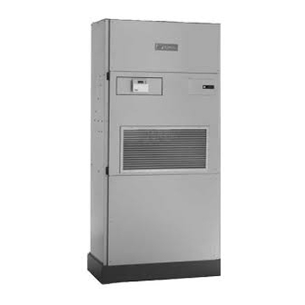
Q-TEC SERIES
PACKAGED HEAT PUMP
Q24H1
Q36H1
Q48H1
Bard Manufacturing Company, Inc.
Bryan, Ohio 43506
Since 1914 . . . Moving ahead, just as planned.
Models:
Q30H1
Q42H1
Q60H1
Manual:
Supersedes:
File:
Date:
2100-519C
2100-519B
Vol. II Tab 14
02-17-12
Manual 2100-519C
Page
1 of 42
Advertisement
Table of Contents
Troubleshooting

Related Manuals for Bard Q-TEC Q24H1


Summary of Contents for Bard Q-TEC Q24H1
- Page 1 PACKAGED HEAT PUMP INSTALLATION Models: INSTRUCTIONS Q24H1 Q30H1 Q36H1 Q42H1 Q48H1 Q60H1 Bard Manufacturing Company, Inc. Manual: 2100-519C Bryan, Ohio 43506 Supersedes: 2100-519B File: Vol. II Tab 14 Since 1914 . . . Moving ahead, just as planned. Date: 02-17-12...
-
Page 2: Table Of Contents
CONTENTS Getting Other Information and Publications tart Up For more information, contact these publishers: ..3 R-410A Refrigerant Required ........27 Topping Off System Charge ........... 27 General Information Safety Practices ............. 27 Model Nomenclature ......... 4 Description of Standard Equipment ....... 28 Shipping Damage ............ -
Page 3: Getting Other Information And Publications
GETTING OTHER INFORMATION AND PUBLICATIONS These publications can help you install the air FOR MORE INFORMATION, CONTACT conditioner or heat pump. You can usually find these at THESE PUBLISHERS: your local library or purchase them directly from the publisher. Be sure to consult current edition of each standard. -
Page 4: Q-Tec Model Nomenclature
Series General Information MODEL NOMENCLATURE – MODEL HEAT COIL OPTIONS FILTER OPTIONS NUMBER PUMP X - Standard X - 1-Inch Fiberglass Q - Q-T (Standard) REVISION 0Z - 0KW F - 2-Inch Fiberglass CAPACITY | 05 - 5KW P - 2-Inch Pleated 24 - 2 Ton 06 - 6KW INTERNAL CONTROLS... -
Page 5: Table 2 Electrical Specifications
TABLE 2 ELECTRICAL SPECIFICATIONS c r i t i u c r i t i u c r i t i u e r i s t l c r i t i u y t i . t k e r i e r i s t i... -
Page 6: Figure 1 Unit Dimensions
Manual 2100-519C Page 6 of 42... -
Page 7: Shipping Damage
SHIPPING DAMAGE FIGURE 2 AIR SEAL UNDER QT UNIT Upon receipt of equipment, the carton should be checked for external signs of shipping damage. The skid must remain attached to the unit until the unit is ready for installation. If damage is found, the receiving party must contact the last carrier immediately, preferably in writing, requesting inspection by the carrier’s agent. -
Page 8: Handling Unit After Removal From Skid
The blade of the appliance cart should be slid under the HANDLING UNIT AFTER REMOVAL wheels of the unit. The strap of the appliance cart FROM SKID should be placed around the unit and strapped tightly. Help will be required to tip the unit back onto the cart. WARNING The unit can be leaned far enough back to be rolled through the door. -
Page 9: Figure 5 Installation With Free Blow Plenum
FIGURE 5 INSTALLATION WITH FREE BLOW PLENUM FIGURE 6 DUCTED APPLICATION Manual 2100-519C Page 9 of 42... -
Page 10: Duct Work
For hot water coil option a QPBHWxx-F for free blow DUCT WORK or QPBHWxx-D for ducted airflow is used. Any heat pump is more critical of proper operating When used with a ducted supply, a QCX Cabinet charge and an adequate duct system than a straight air Extension can be used to conceal the duct work above conditioning unit. -
Page 11: Fresh Air Intake
OPTIONAL REAR DRAIN KITS position other than minimum or maximum position. Optional Rear Drain Kit, Bard Model QCDS48A, is This fresh air assembly is located in the rear of the unit also available for these products. The optional rear... -
Page 12: Figure 9 Optional Side Drain
FIGURE 10 FIGURE 9 OPTIONAL SIDE DRAIN (SIDE VIEW) STANDARD REAR DRAIN INSTALLATION UNIT FIGURE 11 REAR DRAIN (TOP VIEW) DRAIN LINE WALL (MAXIMUM 10" FOR REAR DRAIN) SLEEVE COUPLINGS NOT SHOWN BUT RECOMMENDED FOR EASE OF REMOVABILITY FOR SERVICE. WALL BRACKET WATER... -
Page 13: Figure 12A Optional Rear Drain Kit
Manual 2100-519C Page 13 of 42... -
Page 14: Figure 12B Optional Rear Drain Kit
FIGURE 12B PLUG INSTALLED IN SIDE Q/Tec DRAIN REAR DRAIN CONNECTION IN Q/Tec PRODUCT IMPORTANT ! 1/2" SLIP X 1/2" SLIP X 3/4" NPT TEE SUPPLIED WITH DRAIN BOX KIT 3/4" PLASTIC PIPE NIPPLE (TIGHTEN THREADS SO TEE IS SUPPLIED WITH DRAIN BOX KIT HORIZONTAL TO FLOOR) (APPLY TEFLON TAPE TO THREADS) -
Page 15: Figure 12C Optional Rear Drain Kit
FIGURE 12C REMOVE KNOCK-OUT FOR INDOOR DRAIN HOSE CONNECTOR (If Used) MIS-2471 Manual 2100-519C Page 15 of 42... -
Page 16: Figure 12D Optional Rear Drain Kit
FIGURE 12D DRAIN HOSE FROM INDOOR DRAIN PAN. MOVE HOSE FROM ATTACHMENT IN LOWER DRAIN PAN AND SLIDE ONTO DRAIN BOX BARB FITTING, SECURING WITH SUPPLIED CLAMP IF OUTDOOR PAN IS BYPASSED. ( WILL REDUCE RISK OF ALGAE GROWTH IN THE OUTDOOR PAN BUT AT A SLIGHT COOLING PERFORMANCE REDUCTION OF 2-3% ) MIS-2472... -
Page 17: Figure 13A Unit Mounting - Method 1
FIGURE 13A UNIT MOUNTING - METHOD 1 ENLARGED VIEW OF MOUNTING BRACKET SHOWING SLEEVE TO CABINET ATTACHMENT SIDE TRIM MOUNTING BRACKET (2 PCS.) QWS Series WALL Wall Sleeve SLEEVE SIDE TRIM (2 PCS.) #8 SCREW PROVIDED (LIGHT COLOR) CABINET MOUNTING SIDE PANEL BRACKET #10 HEX... -
Page 18: Installation Instructions
INSTALLATION INSTRUCTIONS MOUNTING THE UNIT alignment to the mounting brackets. This unit must be level from side to side. If adjustments When installing a Q-T unit near an interior wall on the are necessary, shim up under the rollers with left side, a minimum of 8 inches is required;... -
Page 19: Wiring - Main Power
The subbase of the thermostat is factory wired to the FIGURE 15 front panel of the unit. See Figure 18 for wiring COMPONENT LOCATION diagram. Compatible for use with Bard CS2000A* Controller and Energy Recovery Ventilator. SIDE FIELD WIRE The Climate Control Option D is an electronic,... -
Page 20: Low Voltage Connections
LOW VOLTAGE CONNECTIONS NOTE: For total and proper control using DDC, a total of 6 controlled outputs are required (5 if no These units use a grounded 24 volt AC low voltage ventilation system is installed). For proper circuit. system operation under Emergency Heat conditions. -
Page 21: Figure 16 Thermostat Plug Terminals
TABLE 4 WALL THERMOSTATS ; l o ; l o FIGURE 16 MIS-1285 Manual 2100-519C Page 21 of 42... -
Page 22: Figure 17A T-Stat Wiring Diagram "X" Option
FIGURE 17A REMOTE THERMOSTAT WIRING DIAGRAM “X” THERMOSTAT OPTION REMOTE THERMOSTAT WIRING DIAGRAM "X" THERMOSTAT OPTION Low Voltage Thermostat Thermostat #TH522001151 Bard Part #8403-060 Bard Part #8403-058 Terminal Block Plug #2 Orange Orange Red/Yellow W1/E Brown/White Yellow Blue Brown Red/White... - Page 23 FIGURE 17B REMOTE THERMOSTAT WIRING DIAGRAM “X” THERMOSTAT OPTION WITH DEMAND VENTILATION Optional CO2 Controller #C7232A1008 Bard Part #8403-056 24VAC Black Relay Yellow Analog Part #8201-062 Brown Orange Green Plug #2 Orange Orange Red/Yellow W1/E Brown/White Yellow Blue Brown Red/White...
-
Page 24: Figure 17B T-Stat Wiring Diagram "X" Option W/Demand 23 Figure 18 Thermostat Wiring Diagram "A" Option
FIGURE 18 UNIT MOUNTED THERMOSTAT WIRING DIAGRAM “A” THERMOSTAT OPTION Plug #2 Temp. and Humidity Orange Controller PART #8403-060 Brown/White Red/Yellow W1/E Orange Yellow Blue Brown Red/White Black/White Pink 4102-062 A NOTE: On option X or A the CS2000A* (or other field provided means to control ventilation) must be used if any of the motorized ventilation options are installed. -
Page 25: Figure 19 Thermostat Wiring Diagram "D" Option
FIGURE 19 UNIT MOUNTED THERMOSTAT WIRING DIAGRAM “D” THERMOSTAT OPTION Plug #2 Temp. and Humidity Orange Controller PART #8403-060 Red/Yellow W1/E Brown/White Orange Yellow Blue Brown Red/White Black/White 4102-060 Manual 2100-519C Page 25 of 42... -
Page 26: Figure 20 Thermostat Wiring Diagram "H" Option
FIGURE 20 UNIT MOUNTED THERMOSTAT WIRING DIAGRAM “H” THERMOSTAT OPTION CO2 Controller Red/White Part #8403-056 24VAC Black Black/White Relay Yellow Analog Part #8201-062 Brown Orange Plug #2 Orange Orange Green Red/Yellow W1/E Brown/White Orange Temp. and Humidity Yellow Controller Part #8403-060 Blue Brown Red/White... -
Page 27: Start Up
7. Never fill cylinders over 80% of total capacity. TOPPING OFF SYSTEM CHARGE 8. Store cylinders in a cool area, out of direct If a leak has occurred in the system, Bard Manufacturing sunlight. recommends reclaiming, evacuating (see criteria above), 9. -
Page 28: Description Of Standard Equipment
START UP DESCRIPTION OF STANDARD PHASE MONITOR EQUIPMENT All units with three phase scroll compressors are equipped with a 3 phase line monitor to prevent Solid State Electronic Heat Pump Control compressor damage due to phase reversal. Provides efficient 30-minute defrost cycle. A thermistor sensor and speed up terminal for service along with a The phase monitor in this unit is equipped with two 10-minute defrost override are standard on the electronic... -
Page 29: Service Hints
SERVICE HINTS g. Remove screws that attach the duct work to the unit flanges. 1. Caution user to maintain clean air filters at all This unit is equipped with four rollers times. Also, not to needlessly close off supply air mounted to the base. -
Page 30: Vent Options
VENT OPTIONS ENERGY RECOVERY VENTILATOR (Option) BAROMETRIC FRESH AIR DAMPER Before starting, make sure that the power has been (Standard) turned off. The return air grille panel must be removed. Before starting, make sure the power has been turned The energy recovery ventilator (QERV) can be seen off. -
Page 31: Figure 21 Fresh Air Damper Removal
FIGURE 21 FRESH AIR DAMPER REMOVAL MOUNTING SCREW Manual 2100-519C Page 31 of 42... -
Page 32: Figure 22 Qerv Removal
FIGURE 22 QERV REMOVAL POWER CONNECTORS MOUNTING SCREWS LOWER BLOWER ASSEMBLY POWER CONNECTOR FRONT FILL Manual 2100-519C Page 32 of 42... -
Page 33: Figure 23 Co 2 Controller
SEQUENCE OF OPERATION The Climate Control Option “D” is an electronic, programmable thermostat. The thermostat can be set in COOLING – Circuit R-Y makes at thermostat pulling in the heat, cool or automatic mode. When the thermostat compressor contactor, starting the compressor and is set in the heat mode, it can heat only to maintain the outdoor motor. -
Page 34: Pressure Service Ports
PRESSURE SERVICE PORTS As soon as the defrost cycle kicks in remove the shorting instrument from the SPEEDUP terminals. Otherwise the High and low pressure service ports are installed on all units timing will remain accelerated and run through the 1- so that the system operating pressures can be observed. -
Page 35: Figure 24 Defrost Control Board
FIGURE 24 DEFROST CONTROL BOARD TIME (SEC) LOW PRESSURE BYPASS TIMER SWITCH 120* (FACTORY SETTING 120 SECONDS) ACCUMULATED RUN TIME SELECTOR (FACTORY SETTING 30 MIN.) MIS-2684 A Manual 2100-519C Page 35 of 42... -
Page 36: Troubleshooting
TROUBLESHOOTING SOLID STATE HEAT PUMP CONTROL NOTE: If there was no power to 24 volt transformer, the compressor and outdoor fan motor will TROUBLESHOOTING PROCEDURE not start for 5 minutes. This is because of 1. NOTE: A thorough understanding of the defrost the compressor short cycle protection. -
Page 37: Checking Temperature Sensor
CHECKING TEMPERATURE SENSOR 4. If sensor resistance reads very low, then sensor is shorted and will not allow proper operation of the 1. Disconnect temperature sensor from board and from heat pump control. outdoor coil. 5. If sensor is out of tolerance, shorted, open, or reads 2. -
Page 38: Troubleshooting Ge Ecm™ Blower Motors
TROUBLESHOOTING GE ECM MOTORS ™ CAUTION: Symptom Cause/Procedure • Noisy blower or cabinet • Check for loose blower housing, panels, etc. Disconnect power from unit before removing or replacing • High static creating high blower speed? connectors, or servicing motor. To avoid electric shock from - Check for air whistling through seams in the motor’s capacitors, disconnect power and wait at least 5 ducts, cabinets or panels... -
Page 39: Figure 25 Control Disassembly
TROUBLESHOOTING GE ECM ™ MOTORS CONT’D. 8b. IF REPLACING AN ECM 2.3 CONTROL WITH AN ECM Replacing ECM Control Module 2.3 CONTROL, the plastic tab and shorter through-bolts are not needed. To replace the control module for the GE variable-speed indoor blower The control can be oriented in two positions 180°... -
Page 40: Figure 28 Fan Blade Setting
FAN BLADE SETTING DIMENSIONS R-410A Any service work requiring removal or adjustment in REFRIGERANT CHARGE the fan and/or motor area will require that the dimensions in Table 7 be checked and blade adjusted in This unit was charged at the factory with the quantity of or out of the motor shaft accordingly. -
Page 41: Pressure Charts
TABLE 9 COOLING PRESSURE (ALL TEMPERATURES IN DEGREES F) Low side pressure ± 4 psig High side pressure ± 10 psig Tables are based upon rated CFM (airflow) across the evaporator coil. If there is any doubt as to correct operating charge being in the system, the charge should be removed, system evacuated and recharged to serial plate instructions. -
Page 42: Table 10 Heating Pressure
TABLE 10 HEATING PRESSURE (ALL TEMPERATURES IN DEGREES F) Low side pressure ± 4 psig High side pressure ± 10 psig Tables are based upon rated CFM (airflow) across the evaporator coil. If there is any doubt as to correct operating charge being in the system, the charge should be removed, system evacuated and recharged to serial plate instructions.