Table of Contents
Advertisement
Copyright
This publication, including all photographs, illustrations and software, is protected
under international copyright laws, with all rights reserved. Neither this manual, nor
any of the material contained herein, may be reproduced without written consent of
the author.
Version 2.0A
Disclaimer
The information in this document is subject to change without notice. The manufac-
turer makes no representations or warranties with respect to the contents hereof and
specifically disclaims any implied warranties of merchantability or fitness for any
particular purpose. The manufacturer reserves the right to revise this publication and
to make changes from time to time in the content hereof without obligation of the
manufacturer to notify any person of such revision or changes.
Trademark Recognition
Microsoft, MS-DOS and Windows are registered trademarks of Microsoft Corp.
MMX, Pentium, Pentium-II, Pentium-III, Celeron are registered trademarks of Intel
Corporation.
Other product names used in this manual are the properties of their respective
owners and are acknowledged.
Federal Communications Commission (FCC)
This equipment has been tested and found to comply with the limits for a Class B
digital device, pursuant to Part 15 of the FCC Rules. These limits are designed to
provide reasonable protection against harmful interference in a residential installa-
tion. This equipment generates, uses, and can radiate radio frequency energy and, if
not installed and used in accordance with the instructions, may cause harmful inter-
ference to radio communications. However, there is no guarantee that interference
will not occur in a particular installation. If this equipment does cause harmful
interference to radio or television reception, which can be determined by turning the
equipment off and on, the user is encouraged to try to correct the interference by one
or more of the following measures:
•
Reorient or relocate the receiving antenna
•
Increase the separation between the equipment and the receiver
•
Connect the equipment onto an outlet on a circuit different from that to
which the receiver is connected
•
Consult the dealer or an experienced radio/TV technician for help
Shielded interconnect cables and a shielded AC power cable must be employed with
this equipment to ensure compliance with the pertinent RF emission limits governing
this device. Changes or modifications not expressly approved by the system's manu-
facturer could void the user's authority to operate the equipment.
Preface
Preface
Advertisement
Table of Contents

Related Manuals for ECS H55H-CM


Summary of Contents for ECS H55H-CM
- Page 1 Preface Copyright This publication, including all photographs, illustrations and software, is protected under international copyright laws, with all rights reserved. Neither this manual, nor any of the material contained herein, may be reproduced without written consent of the author. Version 2.0A Disclaimer The information in this document is subject to change without notice.
-
Page 2: Declaration Of Conformity
Declaration of Conformity This device complies with part 15 of the FCC rules. Operation is subject to the following conditions: • This device may not cause harmful interference, and • This device must accept any interference received, including interfer- ence that may cause undesired operation Canadian Department of Communications This class B digital apparatus meets all requirements of the Canadian Interference- causing Equipment Regulations. -
Page 3: Table Of Contents
T T T T T ABLE OF CONTENTS ABLE OF CONTENTS ABLE OF CONTENTS ABLE OF CONTENTS ABLE OF CONTENTS Preface Chapter 1 Introducing the Motherboard Introduction...................1 Feature....................2 Specifications................4 Motherboard Components............5 7 7 7 7 7 Chapter 2 Installing the Motherboard Safety Precautions................7 Choosing a Computer Case.............7 Installing the Motherboard in a Case..........7... - Page 4 PC Health Status..............39 Frequency/Voltage Control............42 Load Default Settings............43 Supervisor Password............43 User Password..............44 Save & Exit Setup..............44 Exit Without Saving..............44 Updating the BIOS..............45 47 47 47 47 47 Chapter 4 Using the Motherboard Software About the Software DVD-ROM/CD-ROM.........47 Auto-installing under Windows XP/Vista/7.......47 Running Setup...............48 Manual Installation................50 Utility Software Reference............50...
-
Page 5: Introducing The Motherboard
Chapter 1 Introducing the Motherboard Introduction Thank you for choosing the H55H-CM motherboard. This motherboard is a high performance, enhanced function motherboard designed to support the LGA1156 ® socket for Intel Core i7/Core i5/Core i3 processors for high-end business or personal desktop markets. -
Page 6: Feature
Feature Processor The motherboard uses an LGA1156 type of socket that carries the following features: ® • Accommodates Intel Core i7/Core i5/Core i3 processors • Supports “Hyper-Threading” technology CPU “Hyper-Threading” technology enables the operating system into thinking it’s hooked up to two processors, allowing two threads to be run in parallel, both on separate “logical”... -
Page 7: Bios Firmware
Onboard LAN • IEEE 802.3 Ethernet interface for 1000BASE-T, 100BASE-TX and 10BASE-T applications • Integrated 10/100/1000 transceiver • Operates at half of the PCI Express Specification v1.1 speed Expansion Options The motherboard comes with the following expansion options: • One PCI Express x16 slot for Graphic Interface •... -
Page 8: Specifications
Specifications ® • LGA1156 socket for latest Intel Core i7/Core i5/Core i3 processors • Supports “Hyper-Threading” technology CPU Chipset • Intel H55 Express Chipset Memory • Dual-channel DDR3 memory architecture • 4 x 240-pin DDR3 DIMM sockets support up to 16 GB •... -
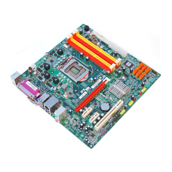
Page 9: Motherboard Components
Motherboard Components Introducing the Motherboard... - Page 10 Table of Motherboard Components LABEL COMPONENTS ® LGA1156 socket for Intel Core i7/Core 1. CPU Socket i5/Core i3 processor 2. CPU_FAN CPU cooling fan connector 3. DIMM1~4 240-pin DDR3 SDRAM slots 4. PWR_FAN Power cooling fan connector 5. FDD1 Floppy disk drive connector 6.
-
Page 11: Installing The Motherboard
Chapter 2 Installing the Motherboard Safety Precautions • Follow these safety precautions when installing the motherboard • Wear a grounding strap attached to a grounded device to avoid dam- age from static electricity • Discharge static electricity by touching the metal case of a safely grounded object before working on the motherboard •... -
Page 12: Checking Jumper Settings
Do not over-tighten the screws as this can stress the motherboard. Checking Jumper Settings This section explains how to set jumpers for correct configuration of the motherboard. Setting Jumpers Use the motherboard jumpers to set system configuration options. Jumpers with more than one pin are numbered. -
Page 13: Checking Jumper Settings
Checking Jumper Settings The following illustration shows the location of the motherboard jumpers. Pin 1 is labeled. Jumper Settings Jumper Type Description Setting (default) 1-2: NORMAL 2-3: CLEAR CMOS CLR_CMOS 3-pin Clear CMOS Before clearing the CLR_CMOS CMOS, make sure to turn off the system. -
Page 14: Installing Hardware
Installing Hardware Installing the Processor Caution: When installing a CPU heatsink and cooling fan make sure that you DO NOT scratch the motherboard or any of the surface-mount resis- tors with the clip of the cooling fan. If the clip of the cooling fan scrapes across the motherboard, you may cause serious damage to the motherboard or its components. -
Page 15: Cpu Installation Procedure
CPU Installation Procedure The following illustration shows CPU installation components. A. Opening of the Load Plate · Put your thumb on the tail of the load plate and press the tail down. · Rotate the load plate to fully open position. -
Page 16: Installing Memory Modules
1. To achieve better airflow rates and heat dissipation, we suggest that you use a high quality fan with 3800 rpm at least. CPU fan and heatsink installation procedures may vary with the type of CPU fan/ heatsink supplied. The form and size of fan/heatsink may also vary. 2. -
Page 17: Installation Procedure
1. For best performance and compatibility, we recommend that users give priority to the yellow DIMMs (DDR3_2/DDR3_4) when installing DIMMs. 2. We suggest users not mix memory type. It is recommended to use the same brand and type memory on this motherboard. Do not remove any memory module from its antistatic packaging until you are ready to install it on the motherboard. - Page 18 Table A: DDR3 (memory module) QVL (Qualified Vendor List) The following DDR3 1600/1333/1066 memory modules have been tested and quali- fied for use with this motherboard. Type Size Vendor Module Name ELPIDA PC3-8500U-7-00-AP 51 2MB Hynix HYMT164U64ZNF8-G8 AA Micron MT4JTF6464AY-1G1B1 A-data M3OSS3H3I3120B5Z Aeneon...
-
Page 19: Expansion Slots
Expansion Slots Installing Add-on Cards The slots on this motherboard are designed to hold expansion cards and connect them to the system bus. Expansion slots are a means of adding or enhancing the motherboard’s features and capabilities. With these efficient facilities, you can in- crease the motherboard’s capabilities by adding hardware that performs tasks that are not part of the basic system. - Page 20 Follow these instructions to install an add-on card: Remove a blanking plate from the system case corresponding to the slot you are going to use. Install the edge connector of the add-on card into the expansion slot. Ensure that the edge connector is correctly seated in the slot. Secure the metal bracket of the card to the system case with a screw.
-
Page 21: Connecting Optional Devices
Connecting Optional Devices Refer to the following for information on connecting the motherboard’s optional devices: F_AUDIO1: Front Panel Audio header This header allows the user to install auxiliary front-oriented microphone and line- out ports for easier access. Signal Name Signal Name PORT 1L AUD_GND PORT 1R... -
Page 22: F_Usb1~3: Front Panel Usb Headers
F_USB1~3: Front Panel USB headers The motherboard has eight USB ports installed on the rear edge I/O port array. Additionally, some computer cases have USB ports at the front of the case. If you have this kind of case, use auxiliary USB connector to connect the front-mounted ports to the motherboard. - Page 23 COM1~2: Onboard serial port headers Connect a serial port extension bracket to this header to add a second serial port to your system. Signal Name Function DCDB Data carry detect NSINB Serial Data In NSOUTB Serial Data Out DTRB Data terminal ready Ground DSRB Date set ready...
-
Page 24: Installing A Sata Hard Drive
Installing a SATA Hard Drive This section describes how to install SATA hard drives. About SATA Connectors Your motherboard features six SATA connectors supporting a total of six drives. SATA refers to Serial ATA (Advanced Technology Attachment) is the standard inter- face for the IDE hard drives which are currently used in most PCs. -
Page 25: Connecting I/O Devices
Connecting I/O Devices The backplane of the motherboard has the following I/O ports: PS2 Mouse Use the upper PS/2 port to connect a PS/2 pointing device. PS2 Keyboard Use the lower PS/2 port to connect a PS/2 keyboard. Parallel Port Use LPT to connect printers or other parallel communica (LPT1) tions devices. -
Page 26: Connecting Case Components
Connecting Case Components After you have installed the motherboard into a case, you can begin connecting the motherboard components. Refer to the following: Connect the CPU cooling fan cable to CPU_FAN. Connect the system cooling fan connector to SYS_FAN. Connect the power cooling fan connector to PWR_FAN. Connect the case switches and indicator LEDs to the F_PANEL. -
Page 27: Atx 12V Power Connector
CPU_FAN: CPU cooling FAN Power Connector Signal Name Function System Ground Power +12V +12V Sense Sensor Users please note that the fan connector supports the CPU cooling fan of 1.1A ~ 2.2A (26.4W max) at +12V. SYS_FAN/PWR_FAN: FAN Power Connectors Signal Name Function System Ground... -
Page 28: Front Panel Header
Front Panel Header The front panel header (F_PANEL) provides a standard set of switch and LED headers commonly found on ATX or Micro ATX cases. Refer to the table below for information: Signal Function Signal Function HD_LED_P Hard disk LED(+) 2 FP PWR/SLP *MSG LED(+) HD_LED_N Hard disk LED(- ) FP PWR/SLP *MSG LED(-) -
Page 29: Using Bios
Chapter 3 Using BIOS About the Setup Utility The computer uses the latest “American Megatrends Inc. ” BIOS with support for Windows Plug and Play. The CMOS chip on the motherboard contains the ROM setup instructions for configuring the motherboard BIOS. The BIOS (Basic Input and Output System) Setup Utility displays the system’s configuration status and provides you with options to set system parameters. -
Page 30: Resetting The Default Cmos Values
Press the delete key or F1 to access the BIOS Setup Utility. CMOS Setup Utility -- Copyright (C) 1985-2009, American Megatrends, Inc. Frequency/Voltage Control Standard CMOS Setup Load Default Settings Advanced Setup Supervisor Password Advanced Chipset Setup User Password Integrated Peripherals Save &... -
Page 31: Bios Navigation Keys
Using BIOS When you start the Setup Utility, the main menu appears. The main menu of the Setup Utility displays a list of the options that are available. A highlight indicates which option is currently selected. Use the cursor arrow keys to move the highlight to other options. -
Page 32: Standard Cmos Setup
Standard CMOS Setup This option displays basic information about your system. CMOS Setup Utility - Copyright (C) 1985-2009, American Megatrends, Inc. Standard CMOS Setup Help Item Date (www mm:dd:yy) Tue 11/17/2009 Time (hh:mm:ss) 00 :00:57 Use [ENTER], [TAB] or [SHIFT-TAB] to SATA1 ATAPI CDROM select a field. - Page 33 Type (Auto) Use this item to configure the type of the IDE device that you specify. If the feature is enabled, it will enhance hard disk performance by reading or writing more data during each transfer. PIO Mode (Auto) Use this item to set the PIO mode to enhance hard disk performance by optimizing the hard disk timing.
-
Page 34: Advanced Setup
3rd Boot Device Removable Drive Hard Disk Drives Press Enter Removable Drives Press Enter Boot Other Device TPM SUPPORT ECS eJIFFY Function Disabled : Move Enter : Select +/-/: Value F10: Save ESC: Exit F1: General Help F9: Optimized Defaults TM Status (TM1/TM2) This item shows TM function status if CPU can support TM function. - Page 35 Quick Power on Self Test (Enabled) Enable this item to shorten the power on testing (POST) and have your system start up faster. You might like to enable this item after you are confident that your system hardware is operating smoothly. Boot Up Numlock Status (On) This item defines if the keyboard Num Lock key is active when your system is started.
- Page 36 This item allows user to protect the PC from impermissable visit. ECS eJIFFY Function (Disabled) Use this item to enable or disable the ECS eJIFFY Function. eJIFFY is ECS unique software program for the quick access to the internet without entering O.S. Please refer to Chapter 5 to know more about eJIFFY.
-
Page 37: Advanced Chipset Setup
Advanced Chipset Setup This page sets up more advanced information about your system. Handle this page with caution. Any changes can affect the operation of your computer. CMOS Setup Utility - Copyright (C) 1985-2009, American Megatrends, Inc. Advanced Chipset Setup Help Item Pre-allocated share mem. -
Page 38: Integrated Peripherals
Integrated Peripherals This page sets up some parameters for peripheral devices connected to the system. CMOS Setup Utility - Copyright (C) 1985-2009, American Megatrends, Inc. Integrated Peripherals SATA Configuration Help Item Onboard SATA Mode Enhanced Onboard Audio Function Enabled Onboard LAN Function Enabled RAID Onboard LAN Boot ROM... -
Page 39: Power Management Setup
Parallel Port IRQ (IRQ7) Use this item to assign IRQ to the parallel port. USB Functions (Enabled) Use this item to enable or disable the USB function. Legacy USB Support (Enabled) Use this item to enable or disable support for legacy USB devices. Press <Esc>... - Page 40 Resume By USB (S3) (Disabled) This item allows you to enable/disable the USB device wakeup function from S3/S4 mode. Resume By PS2 KB (S3) (Disabled) This item enables or disables you to allow keyboard activity to awaken the system from power saving mode. Resume By PS2 MS (S3) (Disabled) This item enables or disables you to allow mouse activity to awaken the system from power saving mode.
-
Page 41: Pci/Pnp Setup
PCI/PnP Setup This page sets up some parameters for devices installed on the PCI bus and those utilizing the system plug and play capability. CMOS Setup Utility - Copyright (C) 1985-2009, American Megatrends, Inc. PCI/PnP Setup Help Item Init Display First Select which graphics controller to use as the primary boot... - Page 42 Smart Fan Function (Press Enter) Scroll to this item and press <Enter> to view the following screen: CMOS Setup Utility - Copyright (C) 1985-2009, American Megatrends, Inc. Smart Fan Function Help Item CPU SMART FAN Control Enabled Options SMART Fan Mode Normal CPU SMART Fan start PWM Disabled...
- Page 43 CMOS Setup Utility - Copyright (C) 1985-2009, American Megatrends, Inc. Smart Fan Function Help Item CPU SMART FAN Control Enabled Options SMART Fan Mode Silent CPU SMART Fan start PWM Normal: auto adjusts SMART Fan start PWM TEMP (-) depending on the CPU DeltaT temperature.
- Page 44 Delta (+3) This item specifies the range that controls CPU temperature and keeps it fromgoing so high or so low when smart fan works. SMART Fan Slope PWM value (4) This item is used to set the Slope Select PWM of the smart fan. CPU Fan Full Speed Offset (-) (7) This item is used to set the CPU fan full speed offset value.
-
Page 45: Frequency/Voltage Control
Frequency/Voltage Control This page enables you to set the clock speed and system bus for your system. The clock speed and system bus are determined by the kind of processor you have in- stalled in your system. CMOS Setup Utility - Copyright (C) 1985-2009, American Megatrends, Inc. Frequency/Voltage Control Help Item Manufacturer: Intel... -
Page 46: Load Default Settings
Configure DRAM Timing by SPD (Auto) When this item is set to enable, the DDR timing is configured using SPD. SPD (Serial Presence Detect) is located on the memory modules, BIOS reads information coded in SPD during system boot up. Memory Hole (Disabled) This item allows users to enable or disable memory hole remapping. -
Page 47: User Password
User Password This page helps you install or change a password. CMOS Setup Utility - Copyright (C) 1985-2009, American Megatrends, Inc. User Password Help Item User Password : Not Installed Install or Change the Change User Password Press Enter password. : Move Enter : Select +/-/: Value... -
Page 48: Updating The Bios
Updating the BIOS You can download and install updated BIOS for this motherboard from the manufacturer’s Web site. New BIOS provides support for new peripherals, improve- ments in performance, or fixes for known bugs. Install new BIOS as follows: If your motherboard has a BIOS protection jumper, change the setting to allow BIOS flashing. -
Page 49: Using The Motherboard Software
Chapter 4 Using the Motherboard Software About the Software DVD-ROM/CD-ROM The support software DVD-ROM/CD-ROM that is included in the motherboard package contains all the drivers and utility programs needed to properly run the bundled products. Below you can find a brief description of each software program, and the location for your motherboard version. -
Page 50: Running Setup
Setup Tab Setup Click the Setup button to run the software installation program. Select from the menu which software you want to install. Browse CD The Browse CD button is the standard Windows command that allows you to open Windows Explorer and show the contents of the support disk. - Page 51 Click Next. The following screen appears: Check the box next to the items you want to install. The default options are recom- mended. Click Next run the Installation Wizard. An item installation screen appears: Follow the instructions on the screen to install the items. Drivers and software are automatically installed in sequence.
-
Page 52: Manual Installation
Windows Vista/7 will appear below UAC (User Account Control) message after the system restart. You must select “Allow” to install the next driver. Continue this process to complete the drivers installation. Manual Installation Insert the disk in the DVD-ROM/CD-ROM drive and locate the PATH.DOC file in the root directory. -
Page 53: Setting Up Ejiffy
Note: eJIFFY is ECS optional feature utility corresponding to the DVD activation and BIOS setup. Please check the hard copy user’s guide or product color-box to see if the model has embodded eJIFFY feature. -
Page 54: Installation And Bios Setup
DVD Activation Finish the DVD utility setup, and then set the BIOS to complete eJIFFY activation. 1. Insert ECS software utility DVD and enter below “Utilities” screen. Click eJIFFY feature item to install. 2. Follow the onscreen instructions to finish eJIFFY setup. - Page 55 3. After setting up eJIFFY under Windows, you can switch eJIFFY display/keyboard language from English to your local language. The changes will be applied after rebooting. Note: The keyboard language selection list offers several more regional keyboard setups to switch with the default English typing. Please refer to the usage FAQ for more tips.
- Page 56 Setup button on the post screen to enter the BIOS setup page after boot up. 5. And then enter the Advanced Setup page to enable the item ECS eJIFFY Func- tion. Press F10 to save the configuration and exit. Restart your computer.
-
Page 57: Entering Ejiffy
Entering eJIFFY The post screen appears within several seconds after boot up and it has three buttons on it, Operating system, eJIFFY and BIOS Setup. Click to enter the normal OS you have installed such as Windows. Click to enter eJIFFY OS. Click to set the BIOS. -
Page 58: Features Icons
Feature Icons The following illustration shows the main feature icons that eJIFFY provides on the menu. eWeb: Firefox for web browsing/webmail and watching flash video. ePix: Photo viewing. ePal: On-line chat tool to use the most popular IMs in the world. (MSN, ICQ , AIM, etc.) Shows ePal on-line connection status. -
Page 59: Usage Faq
Usage FAQ Language Control Panel: Besides setting English as the default interface, eJIFFY offers multi-language displays and keyboard settings for language- switch. Open the language control panel to select a preferable language setting. Keyboard Language Setup to open the language control panel. Step1. - Page 60 Step 2: Click “Keyboard Language” icon to open the keyboard selection list, which offers several regional keyboard settings besides default English keyboard. Step 3: Click the selected keyboard language (e.g. French) and press “OK”. Setting Up eJIFFY...
- Page 61 Tips for Language Switch: Tip 1: Click “Change Keyboard” icon to switch the typing language. The typing language on text box will switch to the selected one: Click again to switch to English typing back. Tip 2. If you use the default English keyboard, eJIFFY still offers other language inputs to switch with English.
- Page 62 Setting Up eJIFFY...
- Page 63 Setting Up eJIFFY...
- Page 64 Tip 3. How to change display language? Open the Language Control Panel and click to show the display language list. Check your desired display language. Your selected display language will be applied after rebooting. Setting Up eJIFFY...
- Page 65 eWeb: Firefox for web browsing/webmail and watching flash video. Q1: How to download files to hard disk through eWeb? Click on the file link directly. Then select “Save File” in the pop-up window. 1. Before downloading files, please “mount” the storage devices to make Note: sure the device is connected with eJIFFY interface.
- Page 66 Q2: How to save image file through eWeb? 1. Select the image you want to save and press the right key of your mouse to show the menu, then click the option “ Save Image As” from the menu. 2. Then the “Save Image” window appears. You may rename the image file in the “Name”...
- Page 67 ePix: Photo viewing. Q1: How to find image files saved in hard disk through ePix? Enter the ePix window, then click the icon “Folder” located in the upper left-hand corner, then follow the path for the files you have saved to view the image files. Setting Up eJIFFY...
- Page 68 Q2: How to use the fit function under slide show? 1. Click “Edit” and select “Preferences” option from the menu. 2. Click “Viewer” and choose “Keep previous zoom” in “After loading an im- age”. Close the window and you can use the fit function under slide show now. Note: ePix supports to view image files only.
- Page 69 Mount/Unmount Disk. Q1: What does it mean for “Mount Disk”? “ Mount” means to connect the storage devices to eJIFFY interface. After plugging the external device to the computer such as USB drives, a new disk icon will appear as the following picture shows. Please click the “mount” prompt on the icon.
- Page 70 Memo Setting Up eJIFFY...
-
Page 71: Trouble Shooting
Chapter 6 Trouble Shooting Start up problems during assembly After assembling the PC for the first time you may experience some start up problems. Before calling for technical support or returning for warranty, this chapter may help to address some of the common questions using some basic troubleshooting tips. -
Page 72: Start Up Problems After Prolong Use
c) The PC suddenly shuts down while booting up. 1. The CPU may experience overheating so it will shutdown to protect itself. Ensure the CPU fan is working properly. 2. From the BIOS setting, try to disable the Smartfan function to let the fan run at default speed. - Page 74 Memo Trouble Shooting...