Table of Contents
Advertisement
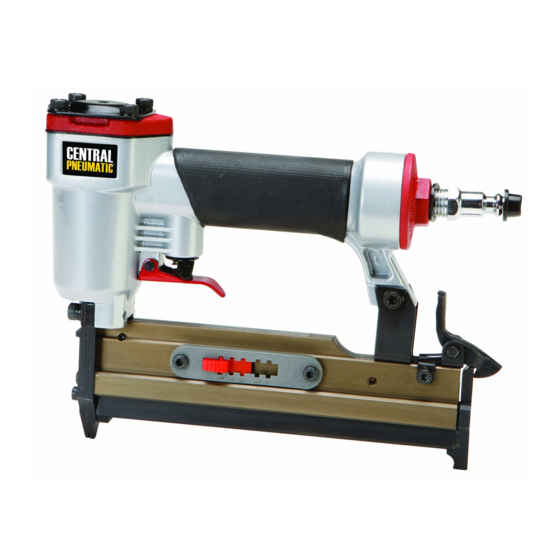
23 GAUGE AIR PIN NAILER
SET UP AND OPERATING INSTRUCTIONS
Visit our website at: http://www.harborfreight.com
Read and understand tool labels and
manual. Failure to follow warnings could
result in DEATH or SERIOUS INJURY.
SAVE THIS MANUAL.
©
Copyright
2010 by Harbor Freight Tools
contained herein may be reproduced in any shape or form without the express written consent of
Harbor Freight Tools. Diagrams within this manual may not be drawn proportionally. Due to continuing
improvements, actual product may differ slightly from the product described herein. Tools required for
assembly and service may not be included.
For technical questions or replacement parts, please call 1‑800‑444‑3353.
Model
68022
®
. All rights reserved. No portion of this manual or any artwork
Advertisement
Table of Contents

Related Manuals for Central Pneumatic 68022


Summary of Contents for Central Pneumatic 68022
- Page 1 23 GAUGE AIR PIN NAILER Model 68022 SET UP AND OPERATING INSTRUCTIONS Visit our website at: http://www.harborfreight.com Read and understand tool labels and manual. Failure to follow warnings could result in DEATH or SERIOUS INJURY. SAVE THIS MANUAL. © ® Copyright 2010 by Harbor Freight Tools .
-
Page 2: Safety Alert Symbol And Signal Words
SAVE THIS MANUAL CAUTION, without the safety alert symbol, is Keep this manual for the safety warnings used to address practices not and precautions, assembly, operating, related to personal injury. inspection, maintenance and cleaning procedures. Write the product’s serial number Symbol Definitions in the back of the manual near the assembly diagram (or month and year of purchase if... -
Page 3: Work Area
WARNING – When using tools, basic Avoid unintentional starting. Be precautions should always be followed, sure the trigger is released before including the following: connecting to the air supply. Do not carry the tool with your finger on the General trigger or connect the tool to the air supply with the trigger pressed. -
Page 4: Air Source
Never carry the tool with finger on Use only accessories that are trigger, the tool is able to fire a fastener. identified by the manufacturer for the specific tool model. Use of an Tool use and care accessory not intended for use with the specific tool model, increases the risk of Use clamps or another practical way injury to persons. -
Page 5: Specific Instructions
SAVE THESE 13. Do not make any modifications to tool. INSTRUCTIONS. 14. Refer to the tool maintenance instructions for detailed information on the proper maintenance of the tool. SPECIFIC INSTRUCTIONS Specific Safety Instructions 15. Fire fasteners into an appropriate work surface only. Do not attempt to Operators and others in work area fire fasteners into surfaces too hard to MUST wear ANSI‑approved safety... - Page 6 24. Do not engrave or stamp anything into Anyone using vibrating tools regularly the housing to avoid weakening it. or for an extended period should first be examined by a doctor and then have 25. WARNING: Some dust created by regular medical check-ups to ensure power sanding, sawing, grinding, medical problems are not being caused...
-
Page 7: Functional Description
FUNCTIONAL DESCRIPTION Unpacking Functional Description When unpacking, make sure that the Specifications item is intact and undamaged. If any parts are missing or broken, please call Harbor Maximum Air 120 PSI Freight Tools at 1-800-444-3353 as soon as Pressure possible. Air Consumption .2 CFM @ 90 PSI •... - Page 8 Air Tool & Spray Gun Portable Setup SKU 68022 For technical questions, please call 1‑800‑444‑3353. Page 8...
- Page 9 Air Tool & Spray Gun Stationary Setup SKU 68022 For technical questions, please call 1‑800‑444‑3353. Page 9...
- Page 10 make operation more efficient, but are discharge any residual air pressure, and not required. release the trigger to prevent accidental operation. WARNING! TO PREVENT SERIOUS INJURY FROM ACCIDENTAL Note: Residual air pressure should not be OPERATION: present after the tool is disconnected Do not install a quick coupler on the from the air supply.
-
Page 11: Work Piece And Work Area Set Up
Set the working air pressure on the OPERATING INSTRUCTIONS Operating Instructions regulator to between 60 and 120 PSI. Do not exceed 120 Max. PSI. Read the ENTIRE IMPORTANT Slide the Nail Length Slider (44) to match SAFETY INFORMATION the corresponding pin length (1/2”, 5/8”, section at the beginning of this 3/4”, 7/8”... - Page 12 Insert the fasteners into the Magazine. After use, to prevent accidents: NOTE: Make sure the fasteners are a. Release the Trigger and set the loaded into Magazine slot head first. Trigger’s Safety Lock. See Figure 2, below. b. Detach the air supply. c.
-
Page 13: Clearing Jams
mechanism and may be highly USER‑MAINTENANCS User‑Maintenance Instructions flammable, causing an explosion. Note: These procedures are in addition to Procedures not specifically the regular checks and maintenance explained in this manual must explained as part of the regular operation be performed only by a qualified of the air-operated tool. - Page 14 up air pressure, and leave the Magazine NOTE: Make sure the fasteners are open. loaded with the pointed ends facing downward. Hold the Nailer pointed away from you and any other people or fragile objects. 14. Slide the Magazine Cover back into Using a Hex Wrench, remove Hex Bolts place and lock it into place using the (36, 37) from the Cover Plate (34).
-
Page 15: Troubleshooting
Troubleshooting Problem Possible Causes Likely Solutions Insufficient 1. Incorrect tool depth setting. 1. Adjust depth setting, if available. fastener depth. 2. Not enough air pressure. 2. Check for loose connections and make sure that air supply is providing enough air pressure (PSI) to the tool’s air inlet. -
Page 16: Please Read The Following Carefully
PLEASE READ THE FOLLOWING CAREFULLY THE MANUFACTURER AND/OR DISTRIBUTOR HAS PROVIDED THE PARTS LIST AND ASSEMBLY DIAGRAM IN THIS MANUAL AS A REFERENCE TOOL ONLY. NEITHER THE MANUFACTURER OR DISTRIBUTOR MAKES ANY REPRESENTATION OR WARRANTY OF ANY KIND TO THE BUYER THAT HE OR SHE IS QUALIFIED TO MAKE ANY REPAIRS TO THE PRODUCT, OR THAT HE OR SHE IS QUALIFIED TO REPLACE ANY PARTS OF THE PRODUCT. - Page 17 Assembly Diagram SKU 68022 For technical questions, please call 1‑800‑444‑3353. Page 17...
- Page 18 Limited 1‑Year Warranty Harbor Freight Tools Co. makes every effort to assure that its products meet high quality and durability standards, and warrants to the original purchaser that this product is free from defects in materials and workmanship for the period of one year from the date of purchase (90 days if used by a professional contractor or if used as rental equipment).