Table of Contents
Advertisement
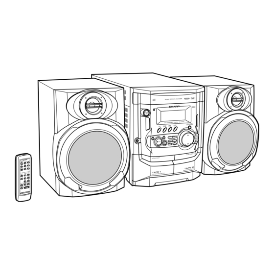
Illustration: CD-XP300
Illustration: CD-XP3300
IMPORTANT SERVICE NOTES (FOR U.S.A. ONLY) ....................................................................................................... 2
SPECIFICATIONS ............................................................................................................................................................. 3
NAMES OF PARTS ........................................................................................................................................................... 4
OPERATION MANUAL ...................................................................................................................................................... 6
QUICK GUIDE (FOR U.S.A. ONLY) .................................................................................................................................. 8
DISASSEMBLY ................................................................................................................................................................ 10
REMOVING AND REINSTALLING THE MAIN PARTS ................................................................................................... 13
ADJUSTMENT ................................................................................................................................................................. 14
NOTES ON SCHEMATIC DIAGRAM .............................................................................................................................. 18
TYPES OF TRANSISTOR AND LED ............................................................................................................................... 18
BLOCK DIAGRAM ........................................................................................................................................................... 19
SCHEMATIC DIAGRAM / WIRING SIDE OF P.W.BOARD ............................................................................................. 22
VOLTAGE ........................................................................................................................................................................ 39
WAVEFORMS OF CD CIRCUIT ...................................................................................................................................... 40
TROUBLESHOOTING ..................................................................................................................................................... 41
FUNCTION TABLE OF IC ................................................................................................................................................ 45
FL DISPLAY ..................................................................................................................................................................... 51
REPLACEMENT PARTS LIST/EXPLODED VIEW
SERVICE MANUAL
MODEL
CD-XP300 Mini Component System consisting of CD-XP300
(main unit) and CP-XP300 (speaker system).
MODEL
CD-XP3300 Mini Component System consisting of CD-XP3300
(main unit) and CP-XP3300 (speaker system).
CONTENTS
SHARP CORPORATION
MINI COMPONENT SYSTEM
CD-XP300
MINI COMPONENT SYSTEM
CD-XP3300
• In the interests of user-safety the set should be restored to its
original condition and only parts identical to those specified be
used.
This document has been published to be used
for after sales service only.
The contents are subject to change without notice.
CD-XP300/CD-XP3300
No. S1203CDXP300/
Page
Advertisement
Table of Contents
Troubleshooting

Related Manuals for Sharp CD-XP300 - Compact Stereo System


Summary of Contents for Sharp CD-XP300 - Compact Stereo System
-
Page 1: Table Of Contents
FUNCTION TABLE OF IC ..............................45 FL DISPLAY ..................................51 REPLACEMENT PARTS LIST/EXPLODED VIEW PACKING OF THE SET (FOR U.S.A. ONLY) This document has been published to be used SHARP CORPORATION for after sales service only. The contents are subject to change without notice. -
Page 2: Important Service Notes (For U.s.a. Only)
CD-XP300/CD-XP3300 IMPORTANT SERVICE NOTES (FOR U.S.A. ONLY) BEFORE RETURNING THE AUDIO PRODUCT (Fire & Shock Hazard) Before returning the audio product to the user, perform the following safety checks. 1. Inspect all lead dress to make certain that leads are not VTVM pinched or that hardware is not lodged between the chassis AC SCALE... -
Page 3: Specifications
CD-XP300/CD-XP3300 FOR A COMPLETE DESCRIPTION OF THE OPERATION OF THIS UNIT, PLEASE REFER TO THE OPERATION MANUAL. SPECIFICATIONS CD-XP300 (Except for Canada)/CD-XP3300 General Cassette deck Power source AC 120 V, 60 Hz Frequency response 50 - 14,000 Hz (Normal tape) Power consumption 107 W Signal/noise ratio... -
Page 4: Names Of Parts
CD-XP300/CD-XP3300 NAMES OF PARTS CD-XP300/CD-XP3300 Display 4 5 6 7 1. CD Pause Indicator 2. Extra Bass Indicator 3. Disc Number Indicators 4. Tape 2 Record Indicator 5. FM Stereo Mode Indicator 6. FM Stereo Receiving Indicator 7. Timer Play Indicator 8. -
Page 5: Remote Control
CD-XP300/CD-XP3300 CD-XP300/CD-XP3300 Remote control 1. Remote Control Transmitter 2. Power On/Stand-by Button 3. Disc Number Select Buttons 4. CD Random Button 5. CD Memory Button 6. Tape 2 Record Pause Button 7. CD Track Down or Fast Reverse, Tape 2 Rewind Button 8. -
Page 6: Operation Manual
Many potential problems can be resolved by the owner without calling a service tech- nician. If something is wrong with this product, check the following before calling your autho- Symptom Possible cause rized SHARP dealer or service center. Cannot record. Is the erase-prevention tab removed? General Cannot record tracks with proper Is it a normal tape? (You cannot record on sound quality. -
Page 7: Troubleshooting Chart
CD-XP300/CD-XP3300 Remote control Troubleshooting chart Test of the remote control If trouble occurs Face the remote control directly to the remote When this product is subjected to strong external interference (mechanical shock, Remote sensor sensor on the unit. excessive static electricity, abnormal supply voltage due to lightning, etc.) or if it is 8"... -
Page 8: Quick Guide (For U.s.a Only)
CD-XP300/CD-XP3300 QUICK GUIDE (FOR U.S.A ONLY) – 8 –... - Page 9 CD-XP300/CD-XP3300 – 9 –...
-
Page 10: Disassembly
CD-XP300/CD-XP3300 DISASSEMBLY Caution on Disassembly CD-XP300/CD-XP3300 Follow the below-mentioned notes when disassembling Top Cabinet the unit and reassembling it, to keep it safe and ensure Front (A1)x2 excellent performance: Panel ø3x12mm 1. Take cassette tape and compact disc out of the unit. 2. - Page 11 CD-XP300/CD-XP3300 (E2)x2 (L1)x3 Loading Tray (E3)x1 (E1)x2 ø3x10mm (E2)x1 (F3)x1 Front Panel (F2)x1 Headphones Power PWB Transformer (E4)x1 (L1)x3 Main PWB (F2)x1 Figure 11-4 (F1)x2 ø3x10mm (M1)x2 Figure 11-1 ø3x10mm Loading (G2)x1 Tray CD Servo (M3)x2 Front Panel Display PWB (M2)x1 (G1)x12 ø3x10mm...
- Page 12 CD-XP300/CD-XP3300 CP-XP300 REMOVAL PROCEDURE FIGURE STEP Woofer 1. Front Panel ..... (A1) x1 12-1 2. Screw ...... (A2) x4 12-2 Tweeter 1. Screw ...... (B1) x2 12-2 (A1)x1 Tweeter (B1)x2 ø3x10mm Screwdriver Speaker Box Speaker Box Woofer Driver should be pried away (A2)x4 from Speaker Box.
-
Page 13: Removing And Reinstalling The Main Parts
CD-XP300/CD-XP3300 REMOVING AND REINSTALLING THE MAIN PARTS TAPE MECHANISM SECTION TAPE 2 Clutch Ass'y Perform steps 1 to 7 and 8 of the disassembly method to remove the tape mechanism. Record/Playback Head How to remove the record/playback and erase heads (TAPE 2) (See Fig. 13-1) 1. -
Page 14: Adjustment
CD-XP300/CD-XP3300 CD MECHANISM SECTION Loading Loading Perform steps 1, 2, 3, 10, 11,12 and 13 of the disassembly Motor PWB Motor method to remove the CD mechanism. Loading Tray How to remove the loading motor (See Fig. 14-1) (A1)x6 1. Bend the hooks (A1) x 6 pcs., to remove the loading motor. Figure 14-1 How to remove the pickup (See Fig. -
Page 15: Tuner Section
CD-XP300/CD-XP3300 TUNER SECTION CD SECTION fL: Low-range frequency • Adjustment fH: High-range frequency Since this CD system incorporates the following automatic adjustment functions, readjustment is not needed when AM IF/RF replacing the pickup. Therefore, different PWBs and pickups Signal generator: 400 Hz, 30%, AM modulated can be combined freely. -
Page 16: Test Mode
CD-XP300/CD-XP3300 TEST MODE Setting the test mode Any one of test mode can be set by pressing several keys as follows. <X-BASS> + <CD> + <POWER> TEST: CD operation test. Function: -CD test mode. -Enter test mode. T E S T IL isn't done OPEN/CLOSE operation is using manual. - Page 17 CD-XP300/CD-XP3300 Standard Specification of Stereo System Error Message Display Contents Error Contents DISPLAY Notes Output while Device Protection Operation. TIMER LED While in Protect Circuit Operate. FLASHING Over Current Detection. DC Detection. TAPE Mechanism Error. 'ER-TA**' 00: Tape Mechanism Error. 01: Initial Error.
-
Page 18: Notes On Schematic Diagram
CD-XP300/CD-XP3300 NOTES ON SCHEMATIC DIAGRAM Resistor: The indicated voltage in each section is the one measured To differentiate the units of resistors, such symbol as K and by Digital Multimeter between such a section and the chas- M are used: the symbol K means 1000 ohm and the symbol sis with no signal given. -
Page 19: Block Diagram
CD-XP300/CD-XP3300 DISC CLAMP NUMBER OPEN/ CLOSE T/T UP DOWN LOADING TO MAIN SECTION TO DISPLAY SECTION MOTOR – 9 10 CNP8 CNP7 LC78645NE CD SERVO XOUT 17 25 CONT5 SLDO SPDO VCC4 M63001FP VCC1 FOCUS/TRACKING/ VCC2 SPIN/SLED +3.3V DRIVER VCC3 +3.3V 26 27 CONSTANT... - Page 20 CD-XP300/CD-XP3300 AM LOOP ANTENNA IC301 ZD351 ANTENNA TA7358AP 5.1V FM FRONT END FM IF 10.7 MHz T302 CF303 BF301 X351 450 kHz CF351 456 kHz B.P.F T351 CF352 CNP301 AM IF FM RF L312 T301 OSC BUFF IC303 Q302 LA1832S AM TRACKING FM IF DET.
- Page 21 CD-XP300/CD-XP3300 FL701 FL DISPLAY TO CD SECTION TAPE MECHANISM Q705 ASS'Y +B10 RX701 52 51 40 25 13 REMOTE SENSOR +B10 +B10 VLOAD AVDD IC701 SW701-SW705 IX0496AW SW711-SW725 SYSTEM MICROCOMPUTER – 1 2 4 5 6 7 8 11 12 16 1 7 20 21 22 23 24 +B10 +B10...
-
Page 22: Schematic Diagram / Wiring Side Of P.w.board
CD-XP300/CD-XP3300 FM SIGNAL R-CH R601 A_GND PLAYBACK SIGNAL L-CH CD_GND RECORD SIGNAL R602 D_5V A-5V CD SIGNAL D_GND IC601 VIDEO SIGNAL LD+7V LC75341 220/ AUDIO PROCESSOR LD+7V CD_D_GND_(DRIVER) C609 R605 Q603, Q604: SYSTEM MUTE 1/50 A-5V – C603 22/50 VREF D-5V INTERFACE Q603... - Page 23 CD-XP300/CD-XP3300 MAIN PWB-A1 (1/3) JK690 VIDEO/AUX R693 L-CH C691 R691 390P 6.8K VIDEO/AUX R690 C690 6.8K 390P C602 C601 R-CH 0.022 220/16 R692 R603 C603 22/50 VREF C610 R604 1/50 ROUT C608 0.12 RBASS R606 C606 3.9K 0.12 RTRE C612 0.0022 C614 A+10V...
- Page 24 CD-XP300/CD-XP3300 C302 0.001 AM TRACKING AM ANTENNA C331 0.047 C323 0.022 C338 C332 0.001 0.022 T303 D301 C342 DS1SS133 0.022 VD301 AM OSC. SVC348S C335 560P D302 T306 DS1SS133 R336 C334 AM BAND AM LOOP (CH) COVERAGE fL ANTENNA BF301 B.P.F IC301 ANTENNA...
- Page 25 CD-XP300/CD-XP3300 MAIN PWB-A1 (2/3) TP302 C342 C373 R365 0.015 0.022 C371 R358 1/50 3.9K R350 2.7K C372 1/50 C367 1/50 20 19 18 R352 R355 C357 3.3K 2.2/50 T351 C356 0.001 AM IF R388 TP301 R393 3.9K L352 ZD351 100 H DZ5.1BSB C396 100/10...
- Page 26 CD-XP300/CD-XP3300 IC901 – – STK41221 POWER AMP. R903 L902 0.29 H Q903 KTC3199 GR R917 ZD902 ZD903 0.1(3W) DZ15BSB C917 DZ15BSB 0.022(ML) R919 R925 R926 R910 1.8K 1.5K 1.5K Q902 KTC3199 GR R920 C903 C904 1.8K C911 220P 220P R927 R928 100/100 C919...
- Page 27 CD-XP300/CD-XP3300 MAIN PWB-A1 (3/3) FM SIGNAL L902 0.29 H R948 Q903 4.7(1/2W) C3199 GR R942 390(2W) C930 47/50 R943 390(2W) – D912 R1_OUT R949 DS1SS133 FAN MOTOR Q906 KTC3203 Y L1_OUT FAN MOTOR R950 C931 DRIVER 10/50 RL914 FW803 M_+13.5V SP_RLY D911 C929...
- Page 28 CD-XP300/CD-XP3300 DISPLAY PWB-B1 FL701 FL DISPLAY R794 45 44 43 42 41 40 39 38 37 36 35 34 33 32 30 29 28 27 26 25 24 23 22 21 20 19 18 17 16 15 14 13 12 11 10 9 8 7 6 5 4 3 2 C707...
- Page 29 CD-XP300/CD-XP3300 HEADPHONES PWB-B2 9 8 7 6 5 4 3 2 1 12 11 10 M_+13V P27 12 - B SP_RLY R795 FW803 R-CH FROM MAIN PWB C701 1/50 L-CH JK701 HEADPHONES CNP705 FM SIGNAL 93 94 95 96 97 98 99 R763 R702 T-BIAS...
- Page 30 CD-XP300/CD-XP3300 CD SERVO PWB-C CD SIGNAL 100P(CH) 0.022 100P(CH) PICKUP UNIT 100P(CH) 56P(CH) 100P(CH) PICKUP HPC1LX 0.022 VREF VREF 8.2K 1.2K 8.2K 0.047 80 79 78 77 76 75 74 73 72 71 70 69 8.2K EFMIN 0.001 RFVDD 0.0027 SLCO RSVSS SLCIST...
- Page 31 CD-XP300/CD-XP3300 100P(CH) 0.022 100P(CH) 100P(CH) 56P(CH) 100P(CH) 0.022 CD RES CLAMP SW 2.2K DISC NO 2.2K 78 77 76 75 74 73 72 71 70 69 68 67 66 65 64 63 62 61 LRCK ASDFIN ASDACK DATA SLCO ASLRCK SLCIST 16MOUT EFLG...
- Page 32 CD-XP300/CD-XP3300 P36 4 - A P35 12 - D TO CD SERVO PWB TO DISPLAY PWB CNP7 CNP701 CNS601 FFC701 MAIN PWB-A1 C302 R374 R372 X352 R388 R373 IC302 R359 C382 1 2 3 4 5 6 7 8 9 10 11 R376 C381 C387...
- Page 33 CD-XP300/CD-XP3300 P35 12 - D TO DISPLAY PWB CNP701 FFC701 R136 P37 10 - F FROM TAPE 1 PLAYBACK HEAD R137 R130 R158 R138 R134 R122 C134 C132 C130 C120 C127 R139 C133 R132 C128 R135 C131 R124 R133 C135 C126 C129 R126...
- Page 34 CD-XP300/CD-XP3300 DISPLAY PWB-B1 RX701 C716 5 6 7 8 9 10 11 12 13 14 15 16 17 18 19 R783 FL701 R793 R792 E C B R763 Q705 R702 C703 D714 D713 R703 R704 R705 Q709 R706 3 2 1 XL700 R781 C714...
- Page 35 CD-XP300/CD-XP3300 LED701 SW701 27 28 29 30 31 32 33 34 35 36 37 38 39 40 41 POWER FL701 R792 RD01 C706 IC701 R732 R731 R730 R762 R729 30 31 R736 R718 R768 C720 R766 CNP701 R767 FFC701 SW711 RD11 R773 RD12...
- Page 36 CD-XP300/CD-XP3300 P34 1 - D P32 5 - A FROM DISPLAY PWB FROM MAIN PWB CNS701 CNS601 CD SERVO PWB-C CNP7 1 2 3 4 5 6 7 8 9 10 1 2 3 4 5 6 7 8 CNP8 B C E 20 21 1 2 3...
- Page 37 CD-XP300/CD-XP3300 P34 3 - G TAPE MECHANISM TO DISPLAY PWB ASSEMBLY CNP702 FFC702 TAPE MECHANISM PWB-F SOLENOID SOLENOID TAPE MOTOR TAPE 2 TAPE 1 RECORD/PLAYBACK PLAYBACK HEAD ERASE HEAD HEAD CD LOADING MOTOR PWB-E OPEN/CLOSE T/T UP/DOWN LOADING MOTOR 7 6 5 4 3 2 1 CNP102 CNP101 P33 11 - E...
- Page 38 CD-XP300/CD-XP3300 P34 1 - E P33 11 - G FROM DISPLAY PWB FROM MAIN PWB CNS705 CNS801 POWER PWB-A2 CNP802 C805 CNP801 C806 C807 D803 D801 C802 ZD802 C803 D805 C801 R808 E C B R807 Q801 R806 D802 D806 ZD803 C804 F802...
-
Page 39: Voltage
CD-XP300/CD-XP3300 VOLTAGE IC101 IC601 IC701 IC901 NO. VOLTAGE NO. VOLTAGE NO. VOLTAGE NO. VOLTAGE NO. VOLTAGE NO. VOLTAGE NO. VOLTAGE 1.6 V 3.7 V 4.85 V 4.93 V 44.9 V 1.0 V 3.7 V 4.78 V 4.93 V 24.7 V N.C. -
Page 40: Waveforms Of Cd Circuit
CD-XP300/CD-XP3300 WAVEFORMS OF CD CIRCUIT Stopped Stopped 1999/04/07 09:51:15 CH1=500 mV CH3=500 mV CH1=200 mV CH2=500 mV 500 ms/div 500 ms/div DC 10:1 DC 10:1 (500 ms/div) DC 10:1 DC 10:1 (500 ms/div) NORM:20 kS/s NORM:20 kS/s IC1 21 IC1 21 SPDO IC1 22 IC1 20... -
Page 41: Troubleshooting
CD-XP300/CD-XP3300 TROUBLESHOOTING When the CD does not function When the CD section does not operate when the objective lens of the optical pickup is dirty, this section may not operate. Clean the objective lens, and check the playback operation. When this section does not operate even after the above step is taken, check the following items. - Page 42 CD-XP300/CD-XP3300 Stopped (1) Focus-HF system check. CH1=500 mV CH3=500 mV 500 ms/div DC 10:1 DC 10:1 (500 ms/div) NORM:20 kS/s Although a CD is inserted and the cover is closed, "NO DISC" is displayed. Press the OPEN/CLOSE switch (SW1) without inserting a disc, and try starting the playback operation.
- Page 43 CD-XP300/CD-XP3300 (2) Tracking system check. Check the TE waveform at pin 15 on IC1. The tracking servo is not activated. If the waveform shown in Figure 43-1 appears and soon after Check the peripheral circuits at pins 14, 15 and 20 on IC1, and NO DISC appears ? CNS1A/B.
- Page 44 CD-XP300/CD-XP3300 (4) PLL system check. Stopped 1999/04/05 17:33:17 CH1=500 mV CH3=1 V CH4=1 V 500 ms/div DC 10:1 DC 10:1 DC 10:1 (500 ms/div) NORM:20 kS/s When a disc is loaded, start play operation. PDO1 The HF waveform is normal, but the TOC data cannot be PDO2 read.
-
Page 45: Function Table Of Ic
CD-XP300/CD-XP3300 FUNCTION TABLE OF IC IC1 VHiLC78645NE1: CD Servo (LC78645NE) (1/2) Terminal Name Input/Output Setting in Reset Pin No. Function SLCO Output — Control output. For slice level SLCIST Input — Resistor connection terminal for SLCO output current setting. control. EFMIN Input —... - Page 46 CD-XP300/CD-XP3300 IC1 VHiLC78645NE1: CD Servo (LC78645NE) (2/2) Terminal Name Input/Output Setting in Reset Function Pin No. RVSS — — GND for Right channel. Must be connected to 0 V. Right channel RCHO Output LVDD /2 Right channel output. D/A converter RVDD Input —...
- Page 47 CD-XP300/CD-XP3300 IC1 VHiLC78645NE1: CD Servo (LC78645NE) 75 74 72 71 69 68 66 65 63 62 SLCO DATA SLCIST EFMIN LRCK ASDFIN RFVDD ASDACK RFVSS ASLRCK FIN1 16MOUT FIN2 EFLG TIN1 TIN2 XVSS LC78645NE VREF FSX/16MIN REF1 XOUT XVDD RVDD RFMON RCHO JITTC...
- Page 48 CD-XP300/CD-XP3300 IC601 VHiLC75341/-1: Audio Processor (LC75341) ROUT LOUT LBASS RBASS LTRE RTRE LSEL0 RSEL0 R1 R2 24 23 22 21 20 19 18 17 16 15 14 13 LC75341 10 11 12 Figure 48 BLOCK DIAGRAM OF IC – 48 –...
- Page 49 CD-XP300/CD-XP3300 IC701 RH-iX0496AWZZ: System Microcomputer (IX0496AW) (1/2) Pin No. Port Name Terminal Name Input/Output Function Input (+) Power supply. -20dBATT Output -20dB Attenuator. NO USE Output Open T_BIAS Output Tape record bias. T_T1/T2 Output Tape T1/T2 change. T_REC/PLY Output Tape REC/PLAY change. CD_RESOUT Output CD DSP reset.
- Page 50 CD-XP300/CD-XP3300 IC701 RH-iX0496AWZZ: System Microcomputer (IX0496AW) (2/2) Pin No. Port Name Terminal Name Input/Output Function P120 O/C SW Input CD OPEN/CLOSE SW. P117 MIC SW Input Mic switch input. P116 KARA_LATCH Output Karaoke latch. (When not used. Connect to 0 V.) P115 NO USE Output...
-
Page 51: Fl Display
CD-XP300/CD-XP3300 FL DISPLAY FL701 VVKNA09SS29-1 GRID ASSIGNMENT X-BASS REC ST SLEEP TP TI PTYIPTY MHz TA MEMORY h j k (1G~8G) ANODE CONNECTION X-BASS PTYI MEMORY PRO LOGIC SLEEP – 51 –... - Page 52 CD-XP300/CD-XP3300 — M E M O — – 52 –...
-
Page 53: Parts Guide
“HOW TO ORDER REPLACEMENT PARTS” To have your order filled promptly and correctly, please furnish the For U.S.A. only following information. Contact your nearest SHARP Parts Distributor to order. 1. MODEL NUMBER 2. REF. No. 3. PART NO. 4. DESCRIPTION For location of SHARP Parts Distributor, Please call Toll-Free;... - Page 54 CD-XP300/CD-XP3300 PRICE PRICE DESCRIPTION PARTS CODE DESCRIPTION PART CODE RANK RANK T302 RCILI0017AWZZ AB FM IF CD-XP300/CD-XP3300 T303 RCILA0052AWZZ AE AM Antenna T306 RCILB0067AWZZ AD AM OSC. INTEGRATED CIRCUITS T351 RCILI0019AWZZ AD AM IF COILS VHILC78645NE1 AY CD Servo,LC78645NE VHIM63001FP-1 AX Focus/Tracking/Spin/Sled Driver, M63001FP VP-XHR82K0000...
- Page 55 CD-XP300/CD-XP3300 PRICE PRICE DESCRIPTION PART CODE PARTS CODE DESCRIPTION RANK RANK C125,126 VCEAZA1HW226M J AB 22 F,50V,Electrolytic C615,616 VCEAZA1HW475M J AB 4.7 F,50V,Electrolytic C127,128 VCTYPA1CX223K AA 0.022 F,16V C617~624 VCEAZA1HW105M J AB 1 F,50V,Electrolytic C129,130 VCTYMN1CX332K J AA 0.0033 F,16V C625,626 VCTYMN1CX222K J AA 0.0022 F,16V...
- Page 56 CD-XP300/CD-XP3300 PRICE PRICE DESCRIPTION PARTS CODE DESCRIPTION PART CODE RANK RANK R28,29 VRD-ST2CD222J AA 2.2 kohms,1/6W R393 VRD-MN2BD102J AA 1 kohm,1/8W VRS-CY1JB102J AA 1 kohm,1/16W R395 VRD-MN2BD473J AA 47 kohms,1/8W R32~38 VRD-ST2CD102J AA 1 kohm,1/6W R601~603 VRD-ST2CD102J AA 1 kohm,1/6W R39,40 VRS-CY1JB681J AA 680 ohms,1/16W...
- Page 57 CD-XP300/CD-XP3300 PRICE PRICE DESCRIPTION PART CODE PARTS CODE DESCRIPTION RANK RANK R921 VRD-ST2CD152J AA 1.5 kohms,1/6W SO901 QTANA0423AWZZ J Terminal,Speaker R922 VRN-VV3LAR10J AD 0.1 ohm,3W QSW-M0012AWZZ J AM Switch,Leaf Type [Open/Close] R925,926 VRD-ST2CD152J AA 1.5 kohms,1/6W QSW-M0012AWZZ J AM Switch,Leaf Type [Clamp] R927,928 VRD-ST2EE223J AA 22 kohms,1/4W...
- Page 58 CD-XP300/CD-XP3300 PRICE PRICE DESCRIPTION PARTS CODE DESCRIPTION PART CODE RANK RANK 201-12 HDECQ0850AWSA J Panel,FL Display MSPRD0109AWFJ J AB Spring,Cassette Lock,Tape 1 201-13 JKNBZ0862AWSA Button,Volume [CD-XP300] MSPRD0110AWFJ J AB Spring,Cassette Lock,Tape 2 201-13 JKNBZ0862AWSB Button,Volume [CD-XP3300] MSPRP0057AWFW J AC Spring,Tray Lock 201-14 JKNBZ0863AWSA Button,Operation [CD-XP300]...
-
Page 59: Tweeter
CD-XP300/CD-XP3300 PRICE DESCRIPTION PART CODE RANK P.W.B. ASSEMBLY (Not Replacement Item) 1 PWB-A1~3 92LPWB3838MANS J — Main/Power/Transformer PWB-B1,2 92LPWB3838DPLS J — Display/Headphones PWB-C 92LPWB3838CDUS J — CD Servo PWB-D QPWBF0027AWZZ J AD CD Motor (PWB Only) PWB-E QPWBF0749AWZZ J AD CD Loading Motor (PWB Only) PWB-F 92PF567-677 —... - Page 60 CD-XP300/CD-XP3300 CD-XP300/CD-XP3300 306-2 306-1 306-3 703x2 305x2 PWB-D Figure 7 CD MECHANISM EXPLODED VIEW – 7 –...
- Page 61 CD-XP300/CD-XP3300 CD-XP300/CD-XP3300 BELT CONNECTION 202-1 PWB-A1 FF/REW Tape FF/REW ROLLER Motor ROLLER 615x3 ASS'Y ASS'Y 617x2 IC851 FLYWHEEL FLYWHEEL IC852 ASS'Y ASS'Y MAIN BELT IC853 TAPE2 TAPE1 Silicon Grease 614x10 614x2 614x3 202-2 610x5 230 611x2 Silicon Grease 608x12 PWB-F IC901 PWB-B1 616x2...
- Page 62 CD-XP300/CD-XP3300 CD-XP300/CD-XP3300 609x2 MECHANISM 609x2 PWB-E 619x2 PWB-C Figure 9 CABINET EXPLODED VIEW (2/2) – 9 –...
- Page 63 CD-XP300/CD-XP3300 CP-XP300 SP3, 4 TWEETER SP3, 4 C1, 2 TWEETER Capacitor 2.7 F, 100 V(N.P.) – C1, 2 Capacitor 2.7 F, 100 V(N.P.) SP1, 2 WOOFER – SP1, 2 WOOFER SP3, 4 907x2 904x2 C1, 2 SP1, 2 904x2 908x4 Figure 10 SPEAKER EXPLODED VIEW (1/2) –...
- Page 64 CD-XP300/CD-XP3300 CP-XP3300 SP3, 4 TWEETER SP3, 4 C1, 2 TWEETER Capacitor 2.7 F, 100 V(N.P.) – C1, 2 Capacitor 2.7 F, 100 V(N.P.) SP1, 2 WOOFER – SP1, 2 WOOFER SP3, 4 907x2 904x2 C1,2 SP1, 2 904x2 906x4 Figure 11 SPEAKER EXPLODED VIEW (2/2) –...
-
Page 65: Packing Of The Set (For U.s.a. Only)
CD-XP300/CD-XP3300 PACKING OF THE SET (FOR U.S.A. ONLY) Setting position of switches and knobs Tape Mechanism STOP SPEAKER CP-XP300/CP-XP3300 UNIT CD-XP300/CD-XP3300 SPAKP0013AWZZ1 SSAKH0078AWZZ Polyethylene Bag,Unit Polyethylene Bag, Speaker SPAKA0388AWZZ Packing Add., S I D Left/Right S I D FRONT SPAKA0337AWZZ Transport [CD-XP300] Caution... - Page 66 CD-XP300/CD-XP3300 — M E M O — – 13 –...
- Page 67 CD-XP300/CD-XP3300 — M E M O — – 14 –...
- Page 68 CD-XP300/CD-XP3300 © COPYRIGHT 2002 BY SHARP CORPORATION ALL RIGHTS RESERVED. No part of this publication may be reproduced, stored in a retrieval system, or transmitted in any form or by any means, electronic, mechanical, photocopying, recording, or otherwise, without prior written permission of the publisher.