Table of Contents
Advertisement
Quick Links
SAFETY PRECAUTION FOR SERVICE MANUAL ........................................................................................................... 2
VOLTAGE SELECTION ...................................................................................................................................................... 2
AC POWER SUPPLY CORD AND AC PLUG SDARTOR .................................................................................................. 2
SPECIFICATIONS ............................................................................................................................................................. 3
NAMES OF PARTS ........................................................................................................................................................... 4
OPERATION MANUAL ...................................................................................................................................................... 6
DISASSEMBLY .................................................................................................................................................................. 8
REMOVING AND REINSTALLING THE MAIN PARTS ................................................................................................... 11
ADJUSTMENT ................................................................................................................................................................. 12
NOTES ON SCHEMATIC DIAGRAM .............................................................................................................................. 16
TYPES OF TRANSISTOR AND LED ............................................................................................................................... 16
BLOCK DIAGRAM ........................................................................................................................................................... 17
SCHEMATIC DIAGRAM / WIRING SIDE OF P.W.BOARD ............................................................................................. 20
VOLTAGE ........................................................................................................................................................................ 37
WAVEFORMS OF CD CIRCUIT ...................................................................................................................................... 38
TROUBLESHOOTING ..................................................................................................................................................... 39
FUNCTION TABLE OF IC ................................................................................................................................................ 43
FL DISPLAY ..................................................................................................................................................................... 50
REPLACEMENT PARTS LIST/EXPLODED VIEW
All manuals and user guides at all-guides.com
SERVICE MANUAL
MODEL
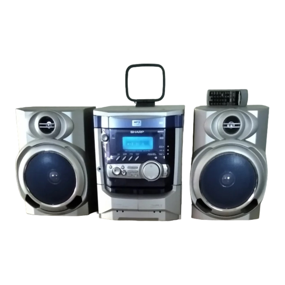
CD-XP300W Mini Component System consisting of CD-XP300W
(main unit) and CP-XP300 (speaker system).
CONTENTS
SHARP CORPORATION
MINI COMPONENT SYSTEM
CD-XP300W
• In the interests of user-safety the set should be restored to its
original condition and only parts identical to those specified be
used.
This document has been published to be used
for after sales service only.
The contents are subject to change without notice.
CD-XP300W
No. S4220CDXP300W
Page
Advertisement
Table of Contents

Related Manuals for Sharp CD-XP300W


Summary of Contents for Sharp CD-XP300W
-
Page 1: Table Of Contents
MINI COMPONENT SYSTEM CD-XP300W MODEL CD-XP300W Mini Component System consisting of CD-XP300W (main unit) and CP-XP300 (speaker system). • In the interests of user-safety the set should be restored to its original condition and only parts identical to those specified be used. -
Page 2: Safety Precaution For Service Manual
All manuals and user guides at all-guides.com CD-XP300W SAFETY PRECAUTION FOR SERVICE MANUAL WARNINGS THE AEL (ACCESSIBLE EMISSION LEVEL) OF THE LASER POWER OUTPUT IS LESS THAN CLASS 1 BUT THE LASER COMPONENT IS CAPABLE OF EMITTING RADIATION EXCEEDING THE LIMIT FOR CLASS 1. THEREFORE IT IS IMPORTANT THAT THE FOLLOWING PRECAUTIONS ARE OBSERVED DURING SERVICING TO PROTECT YOUR EYES AGAINST EXPOSURE TO THE LASER BEAM. -
Page 3: Specifications
All manuals and user guides at all-guides.com CD-XP300W FOR A COMPLETE DESCRIPTION OF THE OPERATION OF THIS UNIT, PLEASE REFER TO THE OPERATION MANUAL. SPECIFICATIONS CD-XP300W General Tuner Power source AC 110/127/220/230 - 240 V, 50/60 Hz Frequency range FM: 88 - 108 MHz... -
Page 4: Names Of Parts
All manuals and user guides at all-guides.com CD-XP300W NAMES OF PARTS CD-XP300W Front panel 1. Disc Tray 2. Timer Set Indicator 3. On/Stand-by Button 4. Tuner (Band) Button 5. CD Button 6. Headphone Socket 7. Microphone Level Control 8. Microphone Socket 9. - Page 5 All manuals and user guides at all-guides.com CD-XP300W CD-XP300W Remote control 1. Remote Control Transmitter 2. On/Stand-by Button 3. Disc Number Select Buttons 4. CD Random Button 5. CD Memory Button 6. Karaoke Mode Button 7. Tape 2 Record Pause Button 8.
-
Page 6: Operation Manual
All manuals and user guides at all-guides.com CD-XP300W OPERATION MANUAL System connections Setting the FM/AM span selector Setting the AC voltage selector Check the setting of the AC voltage selector located on the rear panel before plug- ging the unit into a wall socket. If necessary, adjust the selector to correspond to the AC power voltage used in your area. - Page 7 Many potential problems can be resolved by the owner without calling a service tech- nician. If something is wrong with this product, check the following before calling your autho- Symptom Possible cause rised SHARP dealer or service centre. Cannot record. Is the erase-prevention tab removed? General Cannot record tracks with proper Is it a normal tape? (Yo u cannot record on sound quality.
-
Page 8: Disassembly
All manuals and user guides at all-guides.com CD-XP300W DISASSEMBLY CD-XP300W Caution on Disassembly Follow the below-mentioned notes when disassembling Top Cabinet the unit and reassembling it, to keep it safe and ensure Front (A1) x 2 Panel excellent performance: ø3 x 12mm 1. - Page 9 All manuals and user guides at all-guides.com CD-XP300W (M1) x 3 Loading Tray (E2) x 1 Tape Mechanism (E3) x 1 (E2) x 1 (E2) x 1 (G2) x 1 (E1) x 2 ø3 x 10mm (G1) x 2 ø3 x 10mm...
- Page 10 All manuals and user guides at all-guides.com CD-XP300W CP-XP300 REMOVAL PROCEDURE FIGURE STEP Woofer 1. Front Panel Ass'y ..(A1) x1 10-1 2. Screw ...... (A2) x4 10-2 Tweeter 1. Screw ...... (B1) x2 10-2 (A1) x 1 Tweeter (B1) x 2 ø3 x 10mm...
-
Page 11: Removing And Reinstalling The Main Parts
All manuals and user guides at all-guides.com CD-XP300W REMOVING AND REINSTALLING THE MAIN PARTS TAPE MECHANISM SECTION TAPE 2 Perform steps 1 to 6 and 9 of the disassembly method to Clutch Ass'y remove the tape mechanism. Record/Playback Head How to remove the record/playback and erase heads (TAPE 2) (See Fig. -
Page 12: Adjustment
All manuals and user guides at all-guides.com CD-XP300W CD MECHANISM SECTION Loading Loading Motor PWB Motor Perform steps 1, 2, 3, 11, 12, 13 and 14 of the disassembly Loading method to remove the CD mechanism. Tray How to remove the loading motor (A1) x 5 (See Fig. - Page 13 All manuals and user guides at all-guides.com CD-XP300W TUNER SECTION CD SECTION fL: Low-range frequency • Adjustment fH: High-range frequency Since this CD system incorporates the following automatic • AM IF/RF adjustment functions, readjustment is not needed when replacing the pickup. Therefore, different PWBs and pickups Signal generator: 400 Hz, 30%, AM modulated can be combined freely.
- Page 14 All manuals and user guides at all-guides.com CD-XP300W TEST MODE • Setting the test mode Any one of test mode can be set by pressing several keys as follows. <X-BASS> + <CD> + <POWER> TEST: CD operation test. Function: -CD test mode.
- Page 15 All manuals and user guides at all-guides.com CD-XP300W Standard Specification of Stereo System Error Message Display Contents Error Contents DISPLAY Notes TAPE Mechanism Error. 'ER-TA**' 00: Tape Mechanism Error. 01: Initial Error. Pickup Mechanism Error. 'ER-CD**' 01: PU-IN SW Detection NG.
-
Page 16: Notes On Schematic Diagram
All manuals and user guides at all-guides.com CD-XP300W NOTES ON SCHEMATIC DIAGRAM • Resistor: • The indicated voltage in each section is the one measured by Digital Multimeter between such a section and the chas- To differentiate the units of resistors, such symbol as K and M are used: the symbol K means 1000 ohm and the symbol sis with no signal given. -
Page 17: Block Diagram
All manuals and user guides at all-guides.com CD-XP300W DISC CLAMP NUMBER OPEN/ CLOSE CD LOADING TO MAIN SECTION TO DISPLAY SECTION MOTOR – CNS4 CNP4 9 10 CNP8 CNP7 CONT5 PICKUP LC78645NE CD SERVO XOUT 39 38 VCC4 SLDO SPDO... - Page 18 All manuals and user guides at all-guides.com CD-XP300W ANTENNA FM IF IC301 CF303 T302 TA7358AP BF301 ZD351 FM FRONT END 5.1V B.P.F SO302 10.7 MHz FM ANTENNA TERMINAL CF351 X351 450 kHz 456 kHz L312 T301 T351 CF352 AM IF...
- Page 19 All manuals and user guides at all-guides.com CD-XP300W FL701 FL DISPLAY TAPE MECHANISM Q705 ASS'Y +B10 +B10 RX701 56 55 40 25 13 REMOTE SENSOR +B10 +B10 VLOAD AVDD IC701 SW701~SW707 IX0532AW SW711~SW725 SYSTEM SW601 SPAN MICROCOMPUTER SPAN SELECTOR 1 2 4 5 6 7 8...
-
Page 20: Schematic Diagram / Wiring Side Of P.w.board
All manuals and user guides at all-guides.com CD-XP300W CD SERVO PWB-C CD SIGNAL PICKUP UNIT PICKUP HPC1LX VREF VREF 8.2K 1.2K 8.2K 0.047 80 79 78 77 76 75 74 73 7 8.2K EFMIN 0.001 RFVDD 0.0027 SLCO RSVSS SLCIS... - Page 21 All manuals and user guides at all-guides.com CD-XP300W 100P(CH) 0.022 100P(CH) 100P(CH) 56P(CH) 100P(CH) 0.022 CD RES CLAMP SW 2.2K DISC NO 2.2K 76 75 74 73 72 71 70 69 68 67 66 65 64 63 62 61 LRCK...
- Page 22 All manuals and user guides at all-guides.com CD-XP300W R794 FL701 FL DISPLAY C707 1/50 41 40 39 38 37 36 35 34 33 32 30 29 28 27 19 18 17 16 15 R792 C706 100K 47/25 R793 Q705 KTC3199 GR...
- Page 23 All manuals and user guides at all-guides.com CD-XP300W DISPLAY PWB-B1 9 8 7 6 5 R795 19 18 17 16 15 14 13 12 11 10 C701 1/50 C702 C703 220/10 0.022 85 86 87 88 89 90 91 92 93 94 95 96 97 98 99 100...
- Page 24 All manuals and user guides at all-guides.com CD-XP300W R601 R602 C652 C651 220P 220P IC601 C653 BI601 LC75341 220P CNS601 C601 R-CH AUDIO PROCESSOR 220/16 TO CD A_GND SERVO L-CH Q603,604: SYSTEM MUTE P21 12 - D CD_D_GND 10K C609...
- Page 25 All manuals and user guides at all-guides.com CD-XP300W TO MIC PWB P29 12 - C CNPK1 CNS602 BI602 MAIN PWB-A1 (1/3) R602 C653 C602 220P 0.022 C601 R693 220/16 L-CH R691 C691 R603 JK690 390P 6.8K VIDEO/ C690 R690 AUX IN 390P 6.8K...
- Page 26 All manuals and user guides at all-guides.com CD-XP300W IC901 – STK41221 POWER AMP. C907 0.29 R903 100P Q903 C905 KTC3199 GR 22/50 R912 R917 ZD902 ZD903 Fusible 0.1(3W) R918 DZ150BSB DZ15BSB R934 (1/4W) C917 1.5K R905 0.022(ML) R919 R925 R926 R910 1.8K...
- Page 27 All manuals and user guides at all-guides.com CD-XP300W AMP. PWB-A1 (2/3) FM SIGNAL L902 0.29 µH R948 CNP971 9 GR 4.7(1/2W) R942 390(2W) R943 390(2W) – C930 MOTOR R944 R945 47/50 R934 1.5K 1.5K D912 R1_OUT R949 CNS971 DS1SS133 HEADPHONES...
- Page 28 All manuals and user guides at all-guides.com CD-XP300W AM LOOP ANTENNA SO302 FM ANTENNA TERMINAL CNP301 MAIN PWB-A1 (3/3) BF301 C302 B.P.F. C314 D305 DS1SS133 0.001 0.0047 C303 C308 4.7P(CH) 10P(CH) FM RF C304 IC301 L312 0.01 C315 0.0047 C309...
- Page 29 All manuals and user guides at all-guides.com CD-XP300W MIC PWB-G MIC SIGNAL CK48 220P RK47 CK41 8.2K CK53 100/16 47/25 RK46 ICK1 DS1SS133 CK50 M65856SP CK46 100P MIC AMP. 2.2/50 RK45 RK11 6.8K DATA MIC SW DS1SS133 CK35 0.01 CK51...
- Page 30 All manuals and user guides at all-guides.com CD-XP300W TO CD TO MIC PWB SERVO P P29 12 - G P34 4 - CNPK1 CNP7 CNS602 CNS601 1 2 3 4 5 1 2 3 4 5 6 7 8 9 10 11...
- Page 31 All manuals and user guides at all-guides.com CD-XP300W TO CD SERVO PWB P34 4 - A CNP7 CNS601 1 2 3 4 5 6 7 8 COLOR TABLE BROWN RD(R) ORANGE R136 YELLOW R137 R130 GREEN R158 Q108 R138 BLUE...
- Page 32 All manuals and user guides at all-guides.com CD-XP300W DISPLAY PWB-B1 RX701 C716 7 8 9 10 11 12 13 14 15 16 17 18 C717 R794 R783 R707 R793 B C E R763 C707 C701 Q705 R702 D714 R703 D713...
- Page 33 All manuals and user guides at all-guides.com CD-XP300W TO MAIN PWB P31 11 - C CNP601 FFC701 LED701 6 17 18 19 FL701 27 28 29 30 32 33 34 35 36 37 38 39 40 41 SW701 R738 ON/STAND-BY...
- Page 34 All manuals and user guides at all-guides.com CD-XP300W P32 1 - D P31 7 - A FROM DISPLAY PWB FROM MAIN PWB CNS701 CNS601 CD SERVO PWB-C CNP7 1 2 3 4 5 6 7 8 9 10 1 2 3 4 5 6 7 8...
- Page 35 All manuals and user guides at all-guides.com CD-XP300W P32 4 - H TAPE MECHANISM TO DISPLAY PWB ASSEMBLY CNP702 FFC702 TAPE MECHANISM PWB-F 8 10 SOLENOID SOLENOID TAPE MOTOR TAPE 2 TAPE 1 PLAYBACK HEAD RECORD/PLAYBACK/ ERASE HEAD CD LOADING MOTOR PWB-E...
- Page 36 All manuals and user guides at all-guides.com CD-XP300W FROM DISPLAY PWB POWER PWB-A2 P32 1 - F FROM MAIN PWB CNS705 CNS801 P31 11 - G CNP802 5 4 3 2 1 9 8 7 6 5 4 3 2 1...
-
Page 37: Voltage
All manuals and user guides at all-guides.com CD-XP300W VOLTAGE IC101 IC601 IC701 IC901 NO. VOLTAGE NO. VOLTAGE NO. VOLTAGE NO. VOLTAGE NO. VOLTAGE NO. VOLTAGE NO. VOLTAGE 1.6 V 3.7 V 4.85 V 4.93 V 44.9 V 1.0 V 3.7 V 4.78 V... -
Page 38: Waveforms Of Cd Circuit
All manuals and user guides at all-guides.com CD-XP300W WAVEFORMS OF CD CIRCUIT Stopped Stopped 1999/04/07 09:51:15 CH1=500 mV CH3=500 mV 500 ms/div CH1=200 mV CH2=500 mV 500 ms/div DC 10:1 DC 10:1 (500 ms/div) DC 10:1 DC 10:1 (500 ms/div) -
Page 39: Troubleshooting
All manuals and user guides at all-guides.com CD-XP300W TROUBLESHOOTING When the CD does not function When the CD section does not operate when the objective lens of the optical pickup is dirty, this section may not operate. Clean the objective lens, and check the playback operation. When this section does not operate even after the above step is taken, check the following items. - Page 40 All manuals and user guides at all-guides.com CD-XP300W Stopped (1) Focus-HF system check. CH1=500 mV CH3=500 mV 500 ms/div DC 10:1 DC 10:1 (500 ms/div) NORM:20 kS/s Although a CD is inserted and the cover is closed, "NO DISC" is displayed.
- Page 41 All manuals and user guides at all-guides.com CD-XP300W (2) Tracking system check. Check the TE waveform at pin 15 on IC1. The tracking servo is not activated. If the waveform shown in Figure 41-1 appears and soon after Check the peripheral circuits at pins 14, 15 and 20 on IC1, and NO DISC appears ? CNS1A/B.
- Page 42 All manuals and user guides at all-guides.com CD-XP300W (4) PLL system check. Stopped 1999/04/05 17:33:17 CH1=500 mV CH3=1 V CH4=1 V 500 ms/div DC 10:1 DC 10:1 DC 10:1 (500 ms/div) NORM:20 kS/s When a disc is loaded, start play operation.
-
Page 43: Function Table Of Ic
All manuals and user guides at all-guides.com CD-XP300W FUNCTION TABLE OF IC IC1 VHiLC78645NE1: CD Servo (LC78645NE) (1/2) Terminal Name Input/Output Setting in Reset Function Pin No. SLCO Output — Control output. For slice level SLCIST Input — Resistor connection terminal for SLCO output current setting. - Page 44 All manuals and user guides at all-guides.com CD-XP300W IC1 VHiLC78645NE1: CD Servo (LC78645NE) (2/2) Terminal Name Input/Output Setting in Reset Pin No. Function RVSS — — GND for Right channel. Must be connected to 0 V. Right channel RCHO Output LVDD /2 Right channel output.
- Page 45 All manuals and user guides at all-guides.com CD-XP300W IC1 VHiLC78645NE1: CD Servo (LC78645NE) 75 74 72 71 69 68 66 65 63 62 SLCO DATA SLCIST EFMIN LRCK ASDFIN RFVDD ASDACK RFVSS ASLRCK FIN1 16MOUT FIN2 EFLG TIN1 TIN2 XVSS...
- Page 46 All manuals and user guides at all-guides.com CD-XP300W IC601 VHiLC75341/-1: Audio Processor (LC75341) LOUT ROUT LBASS RBASS LTRE RTRE LSEL0 RSEL0 R1 R2 24 23 22 21 20 19 18 17 16 15 14 13 LC75341 10 11 12 Figure 46 BLOCK DIAGRAM OF IC...
- Page 47 All manuals and user guides at all-guides.com CD-XP300W IC701 RH-iX0532AWZZ: System Microcomputer (IX0532AW) (1/2) Pin No. Port Name Terminal Name Input/Output Function Input (+) Power supply. -20dBATT Output -20dB Attenuator. NO USE Output Open T-BIAS Output Tape record bias. T_T1/T2 Output Tape T1/T2 change.
- Page 48 All manuals and user guides at all-guides.com CD-XP300W IC701 RH-iX0532AWZZ: System Microcomputer (IX0532AW) (2/2) Pin No. Port Name Terminal Name Input/Output Function P120 O/C SW Input CD OPEN/CLOSE SW. P117 MIC SW Input Mic switch input. P116 KARAOKE LATCH Output Karaoke latch.
- Page 49 All manuals and user guides at all-guides.com CD-XP300W ICK1 VHiM65856SP-1: Mic Amp. (M65856SP) (2/2) Pin No. Port Name Input/Output Function LPF1 IN2 Input Low pass filter 1 input 2. Pre-filter before A/D convertor for digital delay. LPF1 OUT Output Low pass filter 1 output.
-
Page 50: Fl Display
All manuals and user guides at all-guides.com CD-XP300W FL DISPLAY FL701 VVKNA09SS29-1 GRID ASSIGNMENT X-BASS REC ST SLEEP TP TI PTYIPTY MHz TA MEMORY h j k (1G~8G) ANODE CONNECTION X-BASS PTYI MEMORY PRO LOGIC SLEEP – 50 –... - Page 51 CD-XP300W PARTS GUIDE MINI COMPONENT SYSTEM CD-XP300W MODEL CD-XP300W Mini Component System consisting of CD-XP300W (main unit) and CP-XP300 (speaker system). “HOW TO ORDER REPLACEMENT PARTS” To have your order filled promptly and correctly, please furnish the For U.S.A. only following information.
- Page 52 All manuals and user guides at all-guides.com CD-XP300W PRICE PRICE DESCRIPTION PARTS CODE DESCRIPTION PART CODE RANK RANK CF351 RFILF0003AWZZ AK FM IF CD-XP300W CF352 RFILA0009AWZZ AE AM IF INTEGRATED CIRCUITS TRANSFORMERS 1 PT801 VHILC78645NE1 AY CD Servo,LC78645NE RTRNP0403AWZZ J...
- Page 53 All manuals and user guides at all-guides.com CD-XP300W PRICE PRICE DESCRIPTION PART CODE PARTS CODE DESCRIPTION RANK RANK AA 0.022 µF,25V C101,102 VCKYMN1HB561K J AA 560 pF,50V C395 VCTYMN1EF223Z AB 100 µF,10V,Electrolytic C103 VCKYBT1HB181K AA 180 pF,50V C396 VCEAZA1AW107M J AA 0.022 µF,25V...
- Page 54 All manuals and user guides at all-guides.com CD-XP300W PRICE PRICE DESCRIPTION PARTS CODE DESCRIPTION PART CODE RANK RANK AA 0.0047 µF,16V CK13 VCTYPA1CX472K R143 VRD-MN2BD473J AA 47 kohms,1/8W AA 0.001 µF,50V CK14 VCKYPA1HB102K R144 VRD-MN2BD223J AA 22 kohms,1/8W AB 0.068 µF,50V,Polyester...
- Page 55 All manuals and user guides at all-guides.com CD-XP300W PRICE PRICE DESCRIPTION PART CODE PARTS CODE DESCRIPTION RANK RANK R741 VRD-MN2BD102J AA 1 kohm,1/8W RD21 VRD-MN2BD102J AA 1 kohm,1/8W R746 VRD-ST2CD102J AA 1 kohm,1/6W RD22 VRD-MN2BD152J AA 1.5 kohms,1/8W R747 VRD-MN2BD472J AA 4.7 kohms,1/8W...
- Page 56 All manuals and user guides at all-guides.com CD-XP300W PRICE PRICE DESCRIPTION PARTS CODE DESCRIPTION PART CODE RANK RANK SW702 92LSWICH1401AT J AC Switch,Key Type 92LCAB3838CASY J AN Side Panel Ass’y,Right [Fast Rewind/Preset Down] 203- 1 ———— — Side Panel,Right SW703...
- Page 57 All manuals and user guides at all-guides.com CD-XP300W PRICE PRICE DESCRIPTION PART CODE PARTS CODE DESCRIPTION RANK RANK XBBSD20P04000 AA Screw,ø2×4mm OTHER SERVICE PART XEBSD26P08000 AA Screw,ø2.6×8mm XEBSD30P08000 AA Screw,ø3×8mm UDSKA0004AFZZ AZ CD Pickup Lens Cleaner XEBSD30P10000 AA Screw,ø3×10mm XEBSD30P12000 AA Screw,ø3×12mm...
- Page 58 All manuals and user guides at all-guides.com CD-XP300W CD-XP300W 306-2 306-1 306-3 703x2 305x2 PWB-D Figure 7 CD MECHANISM EXPLODED VIEW – 7 –...
- Page 59 All manuals and user guides at all-guides.com CD-XP300W BELT CONNECTION CD-XP300W 202-1 PWB-A1 FF/REW Tape FF/REW ROLLER Motor ROLLER ASS'Y ASS'Y 617x2 615x3 IC851 IC852 FLYWHEEL FLYWHEEL ASS'Y ASS'Y MAIN BELT IC853 TAPE2 TAPE1 Silicon Grease 614x17 614x2 610x5 202-2...
- Page 60 All manuals and user guides at all-guides.com CD-XP300W CD-XP300W 609x2 MECHANISM 609x2 PWB-E 619x2 PWB-C Figure 9 CABINET EXPLODED VIEW (2/2) – 9 –...
- Page 61 All manuals and user guides at all-guides.com CD-XP300W CP-XP300 SP3,4 SP3,4 TWEETER TWEETER C1,2 – Capacitor 2.7 µF,100 V(N.P.) SP1,2 WOOFER C1,2 Capacitor 2.7 µF,100 V(N.P.) – SP1,2 WOOFER SP3, 4 907x2 904x2 C1, 2 SP1, 2 904x2 908x4 Figure 10 SPEAKER EXPLODED VIEW...
- Page 62 All manuals and user guides at all-guides.com CD-XP300W — M E M O — – 11 –...
- Page 63 All manuals and user guides at all-guides.com CD-XP300W — M E M O — – 12 –...
- Page 64 All manuals and user guides at all-guides.com CD-XP300W © COPYRIGHT 2002 BY SHARP CORPORATION ALL RIGHTS RESERVED. No part of this publication may be reproduced, stored in a retrieval system, or transmitted in any form or by any means, electronic, mechanical, photocopying, recording, or otherwise, without prior written permission of the publisher.