Sharp CD-XP300H Service Manual
Hide thumbs
Also See for CD-XP300H:
- Service manual (43 pages) ,
- Quick manual (4 pages) ,
- Operation manual (120 pages)
Table of Contents
Advertisement
Quick Links
SAFETY PRECAUTION FOR SERVICE MANUAL ........................................................................................................... 2
IMPORTANT SERVICE NOTES (FOR U.K. ONLY) .......................................................................................................... 2
SPECIFICATIONS ............................................................................................................................................................. 3
NAMES OF PARTS ........................................................................................................................................................... 4
OPERATION MANUAL ...................................................................................................................................................... 5
QUICK GUIDE (FOR U.K. ONLY) ...................................................................................................................................... 8
DISASSEMBLY ................................................................................................................................................................ 10
REMOVING AND REINSTALLING THE MAIN PARTS ................................................................................................... 13
ADJUSTMENT ................................................................................................................................................................. 14
NOTES ON SCHEMATIC DIAGRAM .............................................................................................................................. 18
TYPES OF TRANSISTOR AND LED ............................................................................................................................... 18
BLOCK DIAGRAM ........................................................................................................................................................... 19
SCHEMATIC DIAGRAM / WIRING SIDE OF P.W.BOARD ............................................................................................. 22
VOLTAGE ........................................................................................................................................................................ 39
WAVEFORMS OF CD CIRCUIT ...................................................................................................................................... 40
TROUBLESHOOTING ..................................................................................................................................................... 41
FUNCTION TABLE OF IC ................................................................................................................................................ 45
FL DISPLAY ..................................................................................................................................................................... 51
WIRING OF PRIMARILY SUPPLY LEADS (FOR U.K. ONLY) ....................................................................................... 52
REPLACEMENT PARTS LIST/EXPLODED VIEW
All manuals and user guides at all-guides.com
SERVICE MANUAL
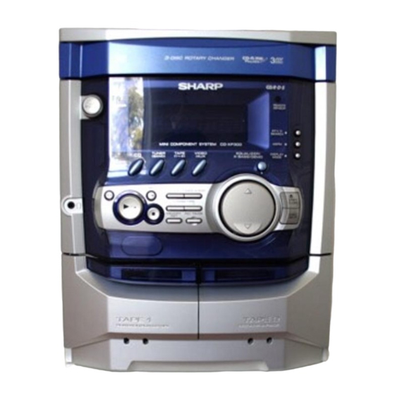
CD-XP300H Mini Component System consisting of CD-XP300H
(main unit) and CP-XP300H (speaker system).
CONTENTS
SHARP CORPORATION
MINI COMPONENT SYSTEM
CD-XP300H
MODEL
• In the interests of user-safety the set should be restored to its
original condition and only parts identical to those specified be
used.
• Note for users in U.K.
Recording and playback of any material may require consent
which SHARP is unable to give. Please refer particularly to the
provisions of Copyright Act 1956, the Dramatic and Musical
Performers Protection Act 1956, the Performers Protection Acts
1963 and 1972 and to any subsequent statutory enactments and
orders.
This document has been published to be used
for after sales service only.
The contents are subject to change without notice.
CD-XP300H
No. S2211CDXP300H
Page
Advertisement
Table of Contents

Related Manuals for Sharp CD-XP300H


Summary of Contents for Sharp CD-XP300H
-
Page 1: Table Of Contents
• Note for users in U.K. Recording and playback of any material may require consent which SHARP is unable to give. Please refer particularly to the provisions of Copyright Act 1956, the Dramatic and Musical Performers Protection Act 1956, the Performers Protection Acts 1963 and 1972 and to any subsequent statutory enactments and orders. - Page 2 All manuals and user guides at all-guides.com CD-XP300H DISASSEMBLY Caution on Disassembly CD-XP300H Follow the below-mentioned notes when disassembling Top Cabinet the unit and reassembling it, to keep it safe and ensure Front (A1) x 2 Panel excellent performance: ø3 x 12mm 1.
- Page 3 All manuals and user guides at all-guides.com CD-XP300H (E2) x 2 (L1) x 3 Loading Tray (E3) x 1 (E1) x 2 ø3 x 10mm (E2) x 1 (F3) x 1 Front Panel (F2) x 1 Headphones Pull Power PWB...
- Page 4 All manuals and user guides at all-guides.com CD-XP300H CP-XP300H PROCEDURE STEP REMOVAL FIGURE Woofer 1. Front Panel ..... (A1) x1 12-1 2. Screw ...... (A2) x4 12-2 Tweeter 1. Screw ...... (B1) x2 12-2 (A1) x 1 Tweeter (B1) x 2 ø3 x 10mm...
-
Page 5: Removing And Reinstalling The Main Parts
All manuals and user guides at all-guides.com CD-XP300H REMOVING AND REINSTALLING THE MAIN PARTS TAPE MECHANISM SECTION TAPE 2 Clutch Ass'y Perform steps 1 to 6 and 8 of the disassembly method to remove the tape mechanism. Record/Playback Head How to remove the record/playback and erase heads (TAPE 2) (See Fig. -
Page 6: Adjustment
All manuals and user guides at all-guides.com CD-XP300H CD MECHANISM SECTION Loading Loading Perform steps 1, 2, 3, 10, 11,12 and 13 of the disassembly Motor PWB Motor method to remove the CD mechanism. Loading Tray How to remove the loading motor (See Fig. - Page 7 All manuals and user guides at all-guides.com CD-XP300H TUNER SECTION CD SECTION fL: Low-range frequency • Adjustment fH: High-range frequency Since this CD system incorporates the following automatic • AM IF/RF adjustment functions, readjustment is not needed when replacing the pickup. Therefore, different PWBs and pickups Signal generator: 400 Hz, 30%, AM modulated can be combined freely.
- Page 8 All manuals and user guides at all-guides.com CD-XP300H TEST MODE • Setting the test mode Any one of test mode can be set by pressing several keys as follows. <X-BASS> + <CD> + <POWER> TEST: CD operation test. Function: -CD test mode.
- Page 9 All manuals and user guides at all-guides.com CD-XP300H Standard Specification of Stereo System Error Message Display Contents Error Contents DISPLAY Notes TAPE Mechanism Error. 'ER-TA**' 00: Tape Mechanism Error. 01: Initial Error. Pickup Mechanism Error. 'ER-CD**' 01: PU-IN SW Detection NG.
-
Page 10: Notes On Schematic Diagram
All manuals and user guides at all-guides.com CD-XP300H NOTES ON SCHEMATIC DIAGRAM • Resistor: • The indicated voltage in each section is the one measured To differentiate the units of resistors, such symbol as K and by Digital Multimeter between such a section and the chas- M are used: the symbol K means 1000 ohm and the symbol sis with no signal given. -
Page 11: Block Diagram
All manuals and user guides at all-guides.com CD-XP300H DISC CLAMP NUMBER OPEN/ CLOSE CD LOADING TO MAIN SECTION TO DISPLAY SECTION MOTOR – CNS4 CNP4 CNP8 9 10 CNP7 CONT5 PICKUP LC78645NE CD SERVO XOUT 39 38 VCC4 SLDO SPDO... - Page 12 All manuals and user guides at all-guides.com CD-XP300H ZD351 FE301 5.1V SO301A FM IF FM FRONT END FM ANTENNA AMP. 10.7 MHz TERMINAL CF301 Q301 CF302 CF351 X351 450 kHz 456 kHz T351 CF352 AM IF PHASE FM/AM (FM/AM) MPX IN...
- Page 13 All manuals and user guides at all-guides.com CD-XP300H FL701 FL DISPLAY TO CD SECTION TAPE MECHANISM Q705 ASS'Y +B10 +B10 RX701 40 25 13 REMOTE SENSOR +B10 +B10 VLOAD AVDD IC701 SW701~SW705 IX0524AW SW711~SW725 SYSTEM SW727~SW729 MICROCOMPUTER 1 2 4 5 6 7 8...
- Page 14 All manuals and user guides at all-guides.com CD-XP300H R601 R602 C652 C651 220P 220P IC601 C653 BI601 LC75341 CNS601 220P C601 R-CH AUDIO PROCESSOR 220/16 TO CD A_GND SERVO L-CH Q603,604: SYSTEM MUTE P31 12 - D D_GND R605 10K C609...
- Page 15 All manuals and user guides at all-guides.com CD-XP300H MAIN PWB-A1 (1/3) C602 0.022 C601 R693 220/16 L-CH R691 C691 R603 JK690 390P 6.8K VIDEO/ C690 R690 AUX IN 390P 6.8K C603 22/50 R-CH R604 C610 R692 1/50 C608 CHASSIS R606 3.9K...
- Page 16 All manuals and user guides at all-guides.com CD-XP300H CHASSIS C302 0.001 L354 LOW PASS FILTER TP302 C342 R365 0.022 R358 3.9K R350 2.7K C367 X351 AM TRACKING 1/50 456 kHz T303 C331 0.047 C330 C323 C338 0.022 0.001 C332 0.022...
- Page 17 All manuals and user guides at all-guides.com CD-XP300H TUNER PWB-A1 (2/3) R370 FILTER TP302 C373 0.015 C371 1/50 RDS PWB-A4 C372 X351 1/50 56 kHz ICT21: RT32 RDS DECORDER IC303 6.8K LA1832S CT23 CT29 CT25 FM IF DET./FM 22P(CH) RT24 0.022...
- Page 18 All manuals and user guides at all-guides.com CD-XP300H IC901 – STK41221 POWER AMP. C907 L902 0.29 µH R903 100P Q903 C905 KTC3199 GR 22/50 R912 R917 ZD902 ZD903 Fusible R918 0.1(3W) DZ150BSB R934 DZ15BSB (1/4W) C917 1.5K C925 R905 0.022(ML)
- Page 19 All manuals and user guides at all-guides.com CD-XP300H AMP. PWB-A1 (3/3) FM SIGNAL L902 0.29 µH Q903 R948 CNP971 KTC3199 GR 4.7(1/2W) R942 390(2W) R943 390(2W) – C930 MOTOR R944 R945 47/50 R934 1.5K D912 1.5K R1_OUT R949 CNS971 DS1SS133...
- Page 20 All manuals and user guides at all-guides.com CD-XP300H R794 FL701 FL DISPLAY C707 1/50 41 40 39 38 37 36 35 34 33 32 30 29 28 27 19 18 17 16 15 14 13 12 11 10 R792 C706...
- Page 21 All manuals and user guides at all-guides.com CD-XP300H DISPLAY PWB-B2 R795 19 18 17 16 15 14 13 12 11 10 9 8 7 6 5 C701 1/50 C702 C703 220/10 0.022 85 86 87 88 89 90 91 92 93 94 95 96 97 98 99 100...
- Page 22 All manuals and user guides at all-guides.com CD-XP300H CD SERVO PWB-C CD SIGNAL 100P(CH) 0.022 100P(CH) PICKUP UNIT 100P(CH) 56P(CH) 100P(CH) PICKUP HPC1LX 0.022 VREF VREF 1.2K 8.2K 8.2K 0.047 80 79 78 77 76 75 74 73 72 71 70 69 8.2K...
- Page 23 All manuals and user guides at all-guides.com CD-XP300H 100P(CH) 0.022 100P(CH) 100P(CH) 56P(CH) 100P(CH) 0.022 CD RES CLAMP SW 2.2K DISC NO 2.2K 78 77 76 75 74 73 72 71 70 69 68 67 66 65 64 63 62 61...
-
Page 24: Voltage
All manuals and user guides at all-guides.com CD-XP300H VOLTAGE IC101 IC601 IC701 IC901 NO. VOLTAGE NO. VOLTAGE NO. VOLTAGE NO. VOLTAGE NO. VOLTAGE NO. VOLTAGE NO. VOLTAGE 3.7 V 4.93 V 1.6 V 4.85 V 44.9 V 1.0 V 3.7 V 4.78 V... -
Page 25: Waveforms Of Cd Circuit
All manuals and user guides at all-guides.com CD-XP300H WAVEFORMS OF CD CIRCUIT Stopped Stopped 1999/04/07 09:51:15 CH1=500 mV CH3=500 mV CH1=200 mV CH2=500 mV 500 ms/div 500 ms/div DC 10:1 DC 10:1 (500 ms/div) DC 10:1 DC 10:1 (500 ms/div) -
Page 26: Troubleshooting
All manuals and user guides at all-guides.com CD-XP300H TROUBLESHOOTING When the CD does not function When the CD section does not operate when the objective lens of the optical pickup is dirty, this section may not operate. Clean the objective lens, and check the playback operation. When this section does not operate even after the above step is taken, check the following items. - Page 27 All manuals and user guides at all-guides.com CD-XP300H Stopped (1) Focus-HF system check. CH1=500 mV CH3=500 mV 500 ms/div DC 10:1 DC 10:1 (500 ms/div) NORM:20 kS/s Although a CD is inserted and the cover is closed, "NO DISC" is displayed.
- Page 28 All manuals and user guides at all-guides.com CD-XP300H (2) Tracking system check. Check the TE waveform at pin 15 on IC1. The tracking servo is not activated. If the waveform shown in Figure 43-1 appears and soon after Check the peripheral circuits at pins 14, 15 and 20 on IC1, and NO DISC appears ? CNS1A/B.
- Page 29 All manuals and user guides at all-guides.com CD-XP300H (4) PLL system check. Stopped 1999/04/05 17:33:17 CH1=500 mV CH3=1 V CH4=1 V 500 ms/div DC 10:1 DC 10:1 DC 10:1 (500 ms/div) NORM:20 kS/s When a disc is loaded, start play operation.
-
Page 30: Fl Display
All manuals and user guides at all-guides.com CD-XP300H FL DISPLAY FL701 VVKNA09SS29-1 GRID ASSIGNMENT X-BASS REC ST SLEEP TP TI PTYIPTY MHz TA MEMORY h j k (1G~8G) ANODE CONNECTION X-BASS PTYI MEMORY PRO LOGIC SLEEP – 51 –... -
Page 31: Wiring Of Primarily Supply Leads (For U.k. Only)
All manuals and user guides at all-guides.com CD-XP300H WIRING OF PRIMARILY SUPPLY LEADS (FOR U.K. ONLY) If any one of the bands shown in Fig. 52 is removed for some reason, be sure replace it to the original position and same appearance as before. - Page 32 CD-XP300H PARTS GUIDE MINI COMPONENT SYSTEM CD-XP300H MODEL CD-XP300H Mini Component System consisting of CD-XP300H (main unit) and CP-XP300H (speaker system). “HOW TO ORDER REPLACEMENT PARTS” To have your order filled promptly and correctly, please furnish the For U.S.A. only following information.
- Page 33 All manuals and user guides at all-guides.com CD-XP300H PRICE PRICE PART CODE DESCRIPTION PARTS CODE DESCRIPTION RANK RANK TRANSFORMERS CD-XP300H 1 PT801 RTRNP0402AWZZ J BG Power INTEGRATED CIRCUITS 1 PT841 RTRNP0313AWZZ J AN Power T303 RCILA0052AWZZ AE AM Antenna VHILC78645NE1...
- Page 34 All manuals and user guides at all-guides.com CD-XP300H PRICE PRICE DESCRIPTION PARTS CODE DESCRIPTION PART CODE RANK RANK AA 0.001 µF,50V C105,106 VCKYMN1HB561K J AA 560 pF,50V C635~638 VCKYMN1HB102K J AB 1 µF,50V,Electrolytic C107~110 VCKYMN1HB331K J AA 330 pF,50V C639,640 VCEAZA1HW105M J AC 100 µF,16V,Electrolytic...
- Page 35 All manuals and user guides at all-guides.com CD-XP300H PRICE PRICE PART CODE DESCRIPTION PARTS CODE DESCRIPTION RANK RANK VRD-ST2CD470J AA 47 ohms,1/6W R381 VRD-MN2BD103J AA 10 kohm,1/8W VRD-ST2CD3R3J AA 3.3 ohms,1/6W R382 VRD-ST2EE151J AA 150 ohms,1/4W VRD-ST2CD273J AA 27 kohms,1/6W...
- Page 36 All manuals and user guides at all-guides.com CD-XP300H PRICE PRICE DESCRIPTION PARTS CODE DESCRIPTION PART CODE RANK RANK R860 VRD-ST2EE221J AA 220 ohms,1/4W CNP701 QCNCWZF27AWZZ J AE Plug,27Pin R901,902 VRD-MN2BD563J AA 56 kohms,1/8W CNP702 QCNCWZY08AWZZ J AC Socket,8Pin R903,904 VRD-MN2BD102J...
- Page 37 All manuals and user guides at all-guides.com CD-XP300H PRICE PRICE PART CODE DESCRIPTION PARTS CODE DESCRIPTION RANK RANK XHBSD20P05000 AA Screw,ø2×5mm MLOKC0004AWZZ J AD Lock Lever,Cassette,Tape 2 XBBSD20P03000 AA Screw,ø2×3mm MSPRC0033AWFJ J AB Spring,Friction LX-WZ1070AFZZ AA Washer,ø1.5×3.8×0.25mm MSPRD0109AWFJ J AB Spring,Cassette Lock,Tape 1...
- Page 38 All manuals and user guides at all-guides.com CD-XP300H PRICE DESCRIPTION PART CODE RANK P.W.B. ASSEMBLY (Not Replacement Item) 1 PWB-A1~4 92LPWB3842MANS J — Main/Power/Transformer/RDS PWB-B1,2 92LPWB3842DPLS J — Display/Headphones PWB-C 92LPWB3838CDUS J — CD Servo PWB-D QPWBF0027AWZZ J AD CD Motor (PWB Only)
- Page 39 All manuals and user guides at all-guides.com CD-XP300H CD-XP300H 306-2 306-1 306-3 703x2 305x2 PWB-D Figure 7 CD MECHANISM EXPLODED VIEW – 7 –...
- Page 40 All manuals and user guides at all-guides.com CD-XP300H CD-XP300H PWB-A1 PWB-A4 617x2 202-1 615x3 IC851 BELT CONNECTION IC852 FF/REW Tape FF/REW ROLLER Motor ROLLER IC853 ASS'Y ASS'Y Silicon Grease FLYWHEEL FLYWHEEL ASS'Y ASS'Y MAIN BELT TAPE2 TAPE1 610x5 Silicon 614x15...
- Page 41 All manuals and user guides at all-guides.com CD-XP300H CD-XP300H 609x2 MECHANISM 609x2 PWB-E 619x2 PWB-C Figure 9 CABINET EXPLODED VIEW (2/2) – 9 –...
- Page 42 All manuals and user guides at all-guides.com CD-XP300H CP-XP300H SP3,4 SP3,4 TWEETER TWEETER C1,2 – Capacitor 2.7 µF,100 V(N.P.) SP1,2 WOOFER C1,2 Capacitor 2.7 µF,100 V(N.P.) – SP1,2 WOOFER SP3, 4 907x2 904x2 C1, 2 SP1, 2 904x2 908x4 Figure 10 SPEAKER EXPLODED VIEW (1/2)
-
Page 43: Packing Method (For U.k.only)
10,11, S I D 18,19 FRONT CD-XP300H © COPYRIGHT 2002 BY SHARP CORPORATION SHARP CORPORATION ALL RIGHTS RESERVED. AV Systems Group Audio Systems Division No part of this publication may be reproduced, Higashihiroshima, Hiroshima 739-0192, Japan stored in a retrieval system, or transmitted in...