Table of Contents
Advertisement
Quick Links
Advertisement
Chapters
Table of Contents

Related Manuals for Acer Aspire Z1100


Summary of Contents for Acer Aspire Z1100
- Page 1 Aspire Z1100 SERVICE GUIDE...
-
Page 2: Revision History
Refer to the following table for the updates made to this service guide. Date Chapter Updates Service guide files and updates are available on the ACER/CSD Website. For more information, go to http://csd.acer.com.tw.The information in this guide is subject to change without notice. Copyright Copyright ©... - Page 3 Conventions The following conventions are used in this manual: WARNING: Indicates a potential for personal injury. CAUTION: Indicates a potential loss of data or damage to equipment. IMPORTANT: Indicates information that is important to know for the proper completion of a procedure, choice of an option, or completing a task.
-
Page 4: General Information
Acer-authorized Service Providers: Your Acer office may have a different part number code than those given in the FRU list in this service guide. The list provided by your regional Acer office must be used to order FRU parts... -
Page 5: Table Of Contents
CHAPTER 1 Hardware Specifications Features ..........1-5 Operating System . - Page 6 LED 20” ......... . 1-25 LCD Inverter .
- Page 7 CHAPTER 3 Machine Maintenance Procedures Introduction ......... 3-5 General Information .
- Page 8 Fan Module Removal ....... 3-38 Fan Module Installation ......3-38 ODD Connector Removal .
- Page 9 CHAPTER 6 FRU (Field Replaceable Unit) List Exploded Diagrams ........6-4 Main Assembly .
- Page 11 CHAPTER Hardware Specifications...
- Page 12 Features ..........1-5 Operating System .
- Page 13 Display Supported Resolution (GPU Supported Resolution). . 1-27 Camera ......... . 1-27 Mini Card .
-
Page 15: Features
Hardware Specifications and Configurations Features The following is a summary of the computer’s many features: Operating System ® Genuine Windows 7 Home Premium 64-bit ® Genuine Windows 7 Home Basic 64-bit CPU and Chipset AMD E350 Fusion™ APU, dual-core (18 W) ... -
Page 16: Storage
Gigabit Ethernet Webcam: 2.0 MP stand-alone webcam with 1600 x 1200 resolution TV Tuner Acer TV-tuner options: Hybrid TV-tuner supporting worldwide analog/DVB-T (Digital Video Broadcasting-Terrestrial) Hybrid TV-tuner supporting worldwide analog and ATSC (Advanced Television Systems Committee) TV-tuner I/O: ... -
Page 17: I/O Ports
I/O Ports Side: Two USB 2.0 ports Multi-in-1 card reader Headphone and microphone line-out jack Back: Four USB 2.0 ports One audio jack Ethernet (RJ-45) port TV-tuner (optional) Adapter 90 W adapter with power cord Dimension and Weight Dimensions ... -
Page 18: Accessories
Accessories Gateway Wireless / USB keyboard and mouse Software Productivity ZX4250/ZX4251 ® ® Adobe Reader ® Microsoft Office 2010 preloaded (purchase a product key to activate) Windows Live™ Essentials Norton™ Online Backup Trial ® ® ... -
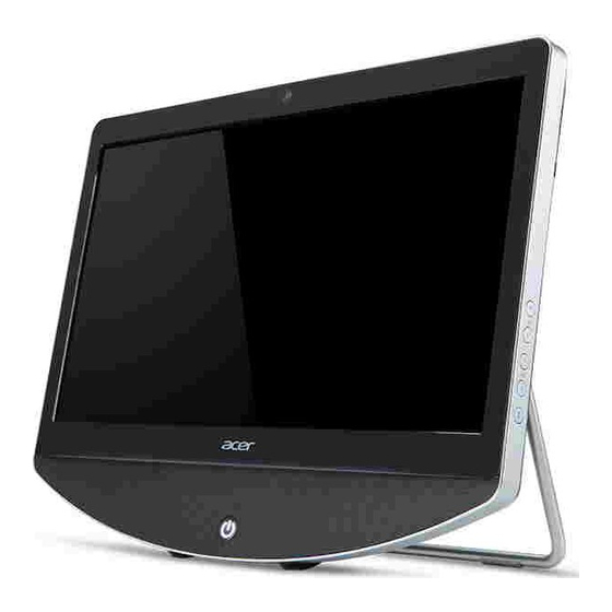
Page 19: Computer Tour
Computer Tour Front View Figure 1-1. Front View Table 1-1. Front View Icon Item Description Integrated Webcam Web camera for video communication. Display Screen Also called Liquid-Crystal Display (LCD), displays computer output (configuration may vary by model). Power Button/Indicator Turns the computer on and off. Indicates the computer's power status. -
Page 20: Left View
Left View Figure 1-2. Left View Table 1-2. Left View Icon Item Description Multi-in-1 card reader Accepts Secure Digital (SD), MultiMediaCard (MMC), Memory Stick PRO (MS PRO), xD-Picture Card (xD). NOTE: Push to remove/install the card. Only one card can operate at any time. USB 2.0 Ports Connect to USB 2.0 devices (e.g., USB mouse, USB camera, USB keyboard). -
Page 21: Right View
Right View Figure 1-3. Right View Table 1-3. Right View Icon Item Description Brightness Increase Increases brightness of screen when pressed Button Brightness Decrease Decreases brightness of screen when pressed Button Volume Increase Increases volume when pressed Button Volume Decrease Decreases volume when pressed Button LED Button... -
Page 22: Rear View
Rear View Figure 1-4. Base View Table 1-4. Base View Icon Item Description IR Blaster Port Connects to a set-top box TV Tuner Connector Connects to a TV cable Audio Jack Connects to external audio source Ethernet (RJ-45) Port Connects to an Ethernet 10/100/1000-based network USB 2.0 Ports Connect to USB 2.0 devices (e.g., USB mouse,... -
Page 23: Using The Keyboard
Using the Keyboard Figure 1-5. Keyboard Lock Keys The keyboard has three lock keys which can be toggled on and off. (Table 1-5) Table 1-5. Keyboard Lock Keys Lock key Description Caps Lock When Caps Lock is on, all alphabetic characters typed are in uppercase. Num Lock When Num Lock is on, the embedded keypad is in numeric mode. -
Page 24: Windows Keys
Windows Keys The keyboard has two keys that perform Windows-specific functions. Windows Logo key Application key Table 1-7. Windows Keys Description Windows Logo Pressed alone, this key has the same effect as clicking on the Windows Start button; it launches the Start menu. It can also be used with other keys to provide a variety of functions. -
Page 25: Hotkeys
Hotkeys Hotkeys or key combinations can be used to access most of the computer's controls like screen brightness and volume output. Figure 1-6. Keyboard Hotkeys To activate hot keys, press and hold the Fn key before pressing the other key in the hotkey combination. - Page 26 Table 1-8. Keyboard Hotkeys (Continued) Hotkey Icon Function Description Fn + 9 Previous Plays the previous media file in the play sequence Fn + 10 Stop Stops media file Fn + 11 Play/Pause Plays or pauses media files Fn + 12 Next Plays the next media file in the play sequence...
-
Page 27: System Block Diagram
System Block Diagram Figure 1-7. System Block Diagram 1-17 Hardware Specifications and Configurations... -
Page 28: Specification Tables
Specification Tables Computer specifications Item Metric Imperial Dimensions Width 485 mm 19.09 inch Depth 382 mm 15.04 inch Height 70.1 mm 2.76 inch Weight: Non-Touch Screen 5.62 kg 12.39 lbs Touch Screen 6.5 kg 14.33 lbs Input power Operating voltage 19V (90W) Operating current... -
Page 29: System Board Major Chips
System Board Major Chips Item Specification Core logic AMD Hudson-D1 FCH FCBGA-605P ATI Mobility Radeon™ HD 6310/6470M GPU RTL8111E-VC-CG USB 2.0 AMD Hudson-D1 FCH Super I/O controller ITE8519 Bluetooth Wireless LITEON,WN6602RH-AA Supports Mini PCIE , PCI_E TV PCMCIA Audio codec Realtek ALC272-X Card reader Realtek RTS-5138... -
Page 30: Cpu Fan True Value Table (Tj=90)
CPU Fan True Value Table (Tj=90) CPU Tj VGA Tj FAN on (°C) FAN off (°C) FAN on (°C) FAN off (°C) dBA FAN speed (RPM) Default Default 1600 25.4 2200 26.8 2400 2800 31.7 3200 32.3 3400 CPU throttling point Critical shutdown by EC System Memory Item... -
Page 31: Video Interface
Video Interface Item Specification Chipset Discrete:Seymour XT M2 UMA: Transmitter ANX3110 eDP to LVDS Output Package FCBGA-962P Interface LVDS Compatibility ANSI/TIA/EIA-644 Sampling rate 60Hz BIOS Item Specification BIOS vendor American Megatrends, Inc. BIOS Version 2.10.1208 BIOS ROM type Winbond (W25Q32BVSSIG) MXIC (MX25L3206EM2I-12G) BIOS ROM size 32Mbits... -
Page 32: Hard Disk Drive (Avl Components)
Item Specification Keyboard (Continued) Features USB Wired keyboard: Key function: Standard keys with Fn combination Wireless keyboard: 2.4G wireless keyboard USB nano-dongle receiver Key function: Standard keys with Fn combination Hard Disk Drive (AVL components) Item Specification Vendor &... - Page 33 Item Specification Hard Disk Drive (AVL components) (Continued) Data heads Drive Format Disks Spindle speed 7200 (RPM) Performance Specifications Buffer size 16MB 16MB 32MB 16MB Interface SATA III Fast data transfer rate (Gbits / sec, max) Media data transfer 1695 rate (Mbytes/sec max) DC Power Requirements...
-
Page 34: Super-Multi Drive
Item Specification Hard Disk Drive (AVL components) (Continued) Media data transfer rate (Mbytes/sec max) DC Power Requirements Voltage tolerance 5V ± 5% Super-Multi Drive Item Specification Vendor & Model name HLDS Super-Multi Drive GT32N/GT34N PLDS Super-Multi DRIVE DS-8A5SH Performance Specification with CD Diskette with DVD Diskette Transfer rate (KB/sec) - Page 35 Item Specification Super-Multi Drive(Continued) Loading mechanism Load: Manual Release: (a) Electrical (Release Button), (b) ATAPI command, (c) Emergency Power Requirement Input Voltage 5 V ± 5% (Operating) BD Drive (N/A) Items Specifications Vendor & Model name Performance Specification Transfer rate (KB/sec) Buffer Memory Interface...
-
Page 36: Led 20
Item Specification LED 20” (Continued) Physical Size (mm) 462.8 (H) x 272.0 (V) x 10.2 (D) mm(Typ.) Electrical Interface LVDS 2 Ports Viewing Angle (degree) R/L 170 (Typ.), U/D 160 (Typ.) CR > 10 (Left) LCD Inverter Item Specification Vendor & Model name LTM270DL02 Brightness conditions Max: Hi 3.3V, Low 0V for duty=100%, Freq.=220Hz,... -
Page 37: Display Supported Resolution (Gpu Supported Resolution)
Display Supported Resolution (GPU Supported Resolution) Resolution 16 bits 32 bits 36 bits 48 bits Others 800x600p/60Hz 16:9 1024x768p/60Hz 16:9 1280x600/60Hz 16:9 1280x720/60Hz 16:9 1280x768/60Hz 16:9 1360x768/60Hz 16:9 Bluetooth Interface - (N/A) Item Specifications Chipset Data throughput Protocol Interface Connector type Supported protocol Bluetooth Module - (N/A) Item... -
Page 38: Audio Codec And Amplifier
Audio Codec and Amplifier Item Specification Audio Controller Realtek ALC272X-GR Features Two stereo DAC support 16/20/24-bit PCM for two independent playback (multiple streaming) Two stereo ADC supports 16/20/24-bit PCM format for two independent recording All DACs support independent 44.1k/48k/96k/192kHz sample ... -
Page 39: Wireless Module - 802.11 B/G/N (Optional)
Item Specification Audio Interface (Continued) Internal microphone Internal speaker/quantity Yes / 2W x2 Wireless Module - 802.11 b/g/n (optional) Item Specification Chipset Ralink RT3090 Data throughput 11-54 Mbps Protocol 802.11 b/g/n Interface PCIE1 Battery (N/A) Item Specification Vendor & Model name Battery Type Pack capacity Number of battery cell... -
Page 40: Usb Port
USB Port Item Specification USB compliance level EHCI The PCH contains seven USB full/low-speed host controllers that support the standard Universal Host Controller Interface (UHCI), Revision 1.1. Each UHCI Host Controller (UHC) includes a root hub with two separate USB ports each, for a total of fourteen USB ports. -
Page 41: System Power Management
System Power Management Item Specification Mech. Off (G3) All devices in the system are turned off completely Soft Off (G2/S5) OS initiated shutdown. All devices in the system are turned off completely Working (G0/S0) Individual devices such as the CPU and hard disc may be power managed in this state Suspend to RAM (S3) CPU set power down... - Page 42 1-32 Hardware Specifications and Configurations...
- Page 43 1-33 Hardware Specifications and Configurations...
- Page 44 1-34 Hardware Specifications and Configurations...
-
Page 45: System Utilities
CHAPTER System Utilities... - Page 46 BIOS Setup Utility........2-3 Navigating the BIOS Utility .
-
Page 47: Bios Setup Utility
System Utilities BIOS Setup Utility This utility is a hardware configuration program built into a computer’s BIOS (Basic Input/Output System). The utility is pre-configured and optimized so most users do not need to run it. If configuration problems occur, the setup utility may need to be run. Refer to Chapter 4, Troubleshooting when a problem arises. -
Page 48: Bios
F8: Save as User-defined System Serial Number F9: Optimized Defaults Asset Tag Number (When Access Level is Administrator) System Date [Sun XX/XX/2011] F10: Save & Exit System Time [XX:XX:XX] Version 2.10.1208. Copyright (C) 2002-2010, Acer Inc. Figure 2-1. BIOS Main System Utilities... - Page 49 Table 2-1 describes the parameters shown in Figure 2-1. Table 2-1. BIOS Main Parameter Description Version BIOS version Build Date Creation date of BIOS EC Firmware System EC version Processor CPU (central processing unit) type Core Frequency Speed of system Count Amount of cores Memory Size...
-
Page 50: Advanced
F8: Save as User-defined F9: Optimized Defaults (When Access Level is Administrator) F10: Save & Exit Version 2.10.1208. Copyright (C) 2002-2010, Acer Inc. Figure 2-2. BIOS Advanced Table 2-2 describes the parameters shown in Figure 2-2. Table 2-2. BIOS Advanced Parameter... -
Page 51: Power
F8: Save as User-defined F9: Optimized Defaults (When Access Level is Administrator) F10: Save & Exit Version 2.10.1208. Copyright (C) 2002-2010, Acer Inc. Figure 2-3. BIOS Power Table 2-3 describes the parameters shown in Figure 2-3. Table 2-3. Parameter Description... -
Page 52: Security
F8: Save as User-defined F9: Optimized Defaults (When Access Level is Administrator) F10: Save & Exit Version 2.10.1208. Copyright (C) 2002-2010, Acer Inc. Figure 2-4. BIOS Security Table 2-4 describes the parameters shown in Figure 2-4. Table 2-4. BIOS Security Parameter... -
Page 53: Setting A Password
Password on Boot must be set to Enabled to activate password feature. Passwords are not case sensitive. A password must be alphanumeric (A-Z, a-z, 0-9), not longer than 12 characters. Setting a Password Perform the following to set a new user or supervisor password: 1. -
Page 54: Removing A Password
4. If new password and confirm new password strings match, the Setup Notice dialog screen is shown (Figure 2-6). If it is not, go to step 5. Setup Notice Changes have been saved. [Continue] Continue Figure 2-6. Setting a Password Confirmation Notice a. -
Page 55: Changing A Password
2. Type current password in Enter Current Password field and press Enter. 3. Press Enter twice typing anything in Enter New Password and Confirm New without Password fields. Computer will set Supervisor Password parameter to Clear. 4. Press F10 to save changes and exit the BIOS Setup Utility. Changing a Password 1. - Page 56 a. Press Enter to return to the BIOS Setup Utility Security menu. b. The Supervisor Password parameter is shown as Clear. c. To try to change the password again, repeat steps 1 through 4. 7. If new password and confirm new password strings do not match, the Setup Warning dialog is shown (Figure 2-12).
-
Page 57: Boot Options
[Press Enter] F8: Save as User-defined F9: Optimized Defaults Quite Boot [Enabled] (When Access Level is Administrator) F10: Save & Exit Halt On [All, but Keyboard] Version 2.10.1208. Copyright (C) 2002-2010, Acer Inc. Figure 2-13. BIOS Boot Options 2-13 System Utilities... -
Page 58: Exit
F8: Save as User-defined F9: Optimized Defaults (When Access Level is Administrator) F10: Save & Exit Version 2.10.1208. Copyright (C) 2002-2010, Acer Inc. Figure 2-14. BIOS Exit Table 2-5 describes the parameters in Figure 2-14. Table 2-5. BIOS Exit Parameter Description Save &... -
Page 59: Bios Flash Utilities
BIOS Flash Utilities BIOS Flash memory updates are required for the following conditions: New versions of system programs New features or options Restore a BIOS when it becomes corrupted. Use the Flash utility to update the system BIOS Flash ROM. NOTE: NOTE: If a Crisis Recovery Disc is not available, create one before BIOS Flash utility is used. -
Page 60: Dos Flash Utility
F10: Save & Exit Halt On [All, but Keyboard] Version 2.10.1208. Copyright (C) 2002-2010, Acer Inc. Figure 2-15. Change BIOS Boot priority Order 4. Copy the BIOS file to USB HDD. 5. Insert the USB HDD and reboot computer to DOS mode. -
Page 61: Wflash4M Utility
Wflash4M Utility Perform the following to use the Wflash4M Utility: 1. Click on the Windows Start icon. 2. Click on All Programs in the Start Menu. (Figure 2-16) Figure 2-16. Windows Start Menu 3. Select Accessories > Command Prompt. (Figure 2-17) Figure 2-17. - Page 62 5. When Command Prompt opens, enter the name of the BIOS file. (Figure 2-18) Figure 2-18. Command Prompt 6. Type Win to access the file. (Figure 2-19) Figure 2-19. Command Prompt 7. Type 64 to access the file. 2-18 System Utilities...
- Page 63 8. Execute Wflash4M to flash BIOS and ME FW. (Figure 2-20 and Figure 2-21) Figure 2-20. Flashing BIOS Figure 2-21. Flashing ME FW 9. Restart system after flash has completed. 2-19 System Utilities...
-
Page 64: Clearing Bios Passwords
Clearing BIOS Passwords If a BIOS password (Supervisor Password and/or User Password) is set, the BIOS will prompt for the password at system POST or upon entering the BIOS setup menu. There are two methods for clearing the BIOS password. A hardware method and a software method. Hardware Method 1. - Page 65 Software Method If wrong supervisor password is entered three times, the System will halt! dialog is shown. (Figure 2-23) Figure 2-23. Supervisor Password Error 1. At a DOS prompt, enter ClearSuPw.exe. (Figure 2-24) Figure 2-24. Clear Supervisor Password Utility 2. When message Clear the SU Pws completely is shown, supervisor password has been removed.
-
Page 66: Using Dmi Tools
Using DMI Tools The DMI (Desktop Management Interface) Tool is for multi-BIOS functionality. This tool is for switching the BIOS branding on multi-brand series. To update the DMI Pool, perform the following: 1. Insert bootable USB HDD into USB port. 2. - Page 67 During the flashing procedure, do press any key. (Figure 2-27) Figure 2-27. DMI Flash Procedure When the DMI flash procedure is completed, the following screen will appear, as shown in Figure 2-28. Figure 2-28. DMI Flash Completed 11. Restart system after flash has completed. 12.
-
Page 68: Using The Lan Mac Eeprom Utility
Using the LAN MAC EEPROM Utility When the MAC Address is removed, the LAN MAC EEPROM Utility is required to rewrite the MAC address to the mainboard. 1. Insert a bootable USB HDD. 2. Copy the MACID file to the bootable USB HDD root directory. 3. - Page 69 8. The Mother Board Information Input screen will appear. (Figure 2-31) Mother Board Information Input Copyright Quanta Computer Corporation 2006 Please Input MACID ----->[ _ _____________] Figure 2-31. Mother Board Information Input Screen 9. Enter the MAC ID number and the MAC ID process begins. NOTE: NOTE: There should be 128 bytes for remaining space.
- Page 70 2-26 System Utilities...
- Page 71 CHAPTER Machine Maintenance Procedures...
- Page 72 Introduction ......... 3-5 General Information .
- Page 73 Thermal Module Removal ......3-40 Thermal Module Installation ......3-41 CPU Removal.
-
Page 75: Introduction
Machine Maintenance Procedures Introduction This chapter contains general information about the computer, a list of tools needed to perform the required maintenance and step by step procedures on how to remove and install components from the computer. General Information The product previews seen in the following procedures may not represent the final product color or configuration. -
Page 76: Screw Table
Screw Table Table 3-1 contains a complete list of the required screws and fasteners required when performing any maintenance on the computer. Table 3-1. Main Screw List Screw Quantity M4.0x7.0 M2.0x3.0 M3.0x5.0 M3.5x8.9 Ni M2.5x4.0 Ni M2.0x4.0 M3.0x6.0 M2.0x6.0 M3.0x5.0 Machine Maintenance Procedures... -
Page 77: Maintenance Flowchart
Maintenance Flowchart The flowchart in Figure 3-1 provides a graphic representation of the module removal and installation sequences. It provides information on what components need to be removed and installed during servicing. Back Cover Mainboard Function Converter Shield Board Board Bracket Middle Frame... -
Page 78: Getting Started
Getting Started The flowchart in Figure 3-1 identifies sections illustrating the entire removal and install sequence. Observe the order of the sequence to avoid damage to any of the hardware components. Perform the following prior to performing any maintenance procedures: 1. -
Page 79: Dummy Card Removal
Dummy Card Removal 1. Push in dummy card (A) to release. (Figure 3-3) Figure 3-3. Dummy Card 2. Remove dummy card (A). Dummy Card Installation 1. Insert dummy card (A). 2. Push in to lock. Machine Maintenance Procedures... -
Page 80: Rear Stand Removal
Rear Stand Removal 1. Remove stand covers (A) from back cover. (Figure 3-4) Figure 3-4. Stand Covers 2. Remove screws (B) from back cover. (Figure 3-5) Figure 3-5. Stand Screws 3. Remove rear stand (C) from guidepins (D) on back cover. 3-10 Machine Maintenance Procedures... -
Page 81: Rear Stand Installation
Rear Stand Installation 1. Align and install rear stand (C) with guidepins (D) on back cover. (Figure 3-4) 2. Install and secure screws (B) to back cover. (Figure 3-5) 3. Install stand covers (A) to back cover. Size Quantity Screw Type M4.0x7.0 3-11 Machine Maintenance Procedures... -
Page 82: Back Cover Removal
Back cover Removal 1. Remove screw (A) from front bezel. (Figure 3-6) Figure 3-6. Back cover Overview 2. Separate back cover from top right corner (B). (Figure 3-7) Figure 3-7. Separating Back Cover 3. Move along edge of back cover in a counterclockwise direction until cover is separated from front bezel. -
Page 83: Back Cover Installation
CAUTION: Use caution when lifting or removing back cover to prevent damage to TV tuner connector. 4. Lift back cover (C) until slots (D) are clear of mainboard connectors, as shown in Figure 3-8. Figure 3-8. Back Cover 5. Remove back cover. Back Cover Installation 1. -
Page 84: Function Board Removal
Function board Removal Prerequisite: Back cover Removal NOTE: NOTE: Function board must be shipped with LCD panel for RMA. 1. Locate function board (A) on middle frame. (Figure 3-9) Figure 3-9. Function board 2. Disconnect the following cables: Right function board cable (C) from function board connector (B) ... -
Page 85: Function Board Installation
Function board Installation 1. Install function board (A) to middle frame. (Figure 3-9) 2. Install and secure screws (F) to middle frame. 3. Connect the following cables: Right function board cable (C) to function board connector (B) Left function board cable (D) to function board connector (E) ... -
Page 86: Converter Board Removal
Converter Board Removal Prerequisite: Back cover Removal 1. Locate converter board (A) on middle frame. (Figure 3-10) Figure 3-10. Converter Board 2. Disconnect the following cables: Converter cable (B) from converter board connector (D) Change board FFC (E) from converter board connector (F) 3. -
Page 87: Change Board Removal
Change Board Removal Prerequisite: Back cover Removal 1. Locate change board (A) on middle frame. (Figure 3-11) Figure 3-11. Change Board 2. Disconnect the following cables: Change board FFC (C) from change board connector (B) Change board FFC (D) from change board connector (E) 3. -
Page 88: Power Board Removal
Power Board Removal Prerequisite: Back cover Removal 1. Locate power board (A) on front bezel. (Figure 3-12) Figure 3-12. Power Board 2. Disconnect power board cable (B) from power board connector (C). 3. Remove screws (D) from front bezel. 4. Remove power board from guidepins (E) on front bezel. Power Board Installation 1. -
Page 89: Infrared Board Removal
Infrared Board Removal Prerequisite: Back cover Removal 1. Locate infrared board (A) on front bezel. (Figure 3-13) Figure 3-13. Infrared Board 2. Disconnect infrared board cable (E) from board connector (D). 3. Remove screw (B) from front bezel. 4. Lift infrared board from guidepins (C) on front bezel. 5. -
Page 90: Infrared Board Installation
Infrared Board Installation 1. Align and install infrared board (A) with guidepins (C) on front bezel. (Figure 3-13) 2. Install and secure screw (D) to front bezel. 3. Connect infrared board cable (E) to board connector (D). 4. Install back cover. Size Quantity Screw Type... -
Page 91: Hdd Module Removal
HDD Module Removal Prerequisite: Back cover Removal 1. Locate HDD module (A) on middle frame. (Figure 3-15) Figure 3-15. HDD Module 2. Disconnect the following cables: HDD cable (B) from mainboard connector (C) HDD cable (D) from mainboard connector (E) 3. -
Page 92: Hdd Module Installation
HDD Module Installation 1. Install HDD module into slots (H) on middle frame. (Figure 3-16) Figure 3-16. Slots on Middle Frame 2. Install and secure screw (F) to middle frame. (Figure 3-15) 3. Connect the following cables: HDD cable (B) to mainboard connector (C) ... -
Page 93: Hdd Bracket Removal
HDD Bracket Removal Prerequisite: HDD Module Removal 1. Disconnect HDD cable (B) from HDD module connector (C). (Figure 3-17) Figure 3-17. HDD Module 2. Remove screws (A) from HDD module. 3. Remove HDD bracket (D) from HDD module. HDD Bracket Installation 1. -
Page 94: Odd Module Removal
ODD Module Removal Prerequisite: Back cover Removal 1. Locate ODD module (A). (Figure 3-18) Figure 3-18. ODD Module 2. Remove screw (C) from middle frame. 3. Slide and remove ODD module from guides (B) on middle frame. 4. Press ODD tray release button (D) on bezel to eject ODD tray. (Figure 3-19) Figure 3-19. - Page 95 5. Slide ODD tray (F) from ODD module. (Figure 3-20) Figure 3-20. ODD Latch and Bezel 6. Unlock latch (G) to separate ODD bezel (H) from tray. 7. Remove ODD bezel. 8. Remove screws (J) from ODD bracket (K) and ODD module. (Figure 3-21) Figure 3-21.
-
Page 96: Odd Module Installation
ODD Module Installation 1. Install ODD bracket (K) to ODD module. (Figure 3-21) 2. Install and secure screws (J) from ODD bracket to ODD module. 3. Install ODD bezel (H) to ODD tray (F). (Figure 3-20) 4. Install and secure latch (G) to tray. 5. -
Page 97: Button Board Removal
Button Board Removal Prerequisite: Back cover Removal ODD Module Removal 1. Locate button board frame on front bezel. (Figure 3-22) Figure 3-22. Button Board 2. Disconnect button board cable (C) from button board connector (B). 3. Remove screws (D) from front bezel. 4. -
Page 98: Button Board Installation
6. Remove button board frame from guidepin (G) on front bezel. 7. Remove screws (H) from button board frame. (Figure 3-24) Figure 3-24. Button Board Screws 8. Remove button board (J) from frame (A). Button Board Installation 1. Install button board (J) to frame (A). (Figure 3-24) 2. -
Page 99: Camera Module Removal
Camera Module Removal Prerequisite: Back cover Removal 1. Disconnect right function board cable (A) from function board connector (B). (Figure 3-25) Figure 3-25. Function board Cable 2. Remove right function board cable from guides (C) on middle frame. 3. Remove screws (D) from camera bracket. (Figure 3-26) Figure 3-26. - Page 100 5. Position camera module at vertical angle to clear latches (F). (Figure 3-27) Figure 3-27. Removing Camera Module 6. Remove camera module from front bezel. 7. Turn camera module over. (Figure 3-28) Figure 3-28. Camera Module Cable 8. Disconnect camera module cable (G) from module connector (H). 3-30 Machine Maintenance Procedures...
-
Page 101: Camera Module Installation
Camera Module Installation 1. Connect camera module cable (G) to module connector (H). (Figure 3-28) 2. Turn camera module over. 3. Position camera module at vertical angle. (Figure 3-27) 4. Install camera module (E) into front bezel until clear of latches (F). 5. -
Page 102: Mainboard Shielding Removal
Mainboard Shielding Removal Prerequisite: Back cover Removal 1. Disconnect the following cables: (Figure 3-29) HDD cable (B) from mainboard connector (C) HDD cable (D) from mainboard connector (E) Figure 3-29. Mainboard Shielding 2. Disconnect TV tuner cable (F) from TV tuner module (G). 3. -
Page 103: Mainboard Shielding Installation
4. Lift mainboard shielding until slots (H) are clear of mainboard connectors, as shown in Figure 3-30. Figure 3-30. Mainboard Shielding Slots 5. Remove mainboard shielding (J). Mainboard Shielding Installation 1. Align slots (H) of mainboard shielding with mainboard connectors. (Figure 3-30) 2. -
Page 104: Dimm Module Removal
DIMM Module Removal Prerequisite: Mainboard Shielding Removal 1. Locate DIMM module (A) on mainboard. (Figure 3-31) Figure 3-31. DIMM Module 2. Push module clips (C) to unlock DIMM module. 3. Disconnect DIMM module (A) from mainboard connector (B). 4. Repeat steps 2 and 3 for remaining DIMM module (D). DIMM Module Installation 1. -
Page 105: Wlan Module Removal
WLAN Module Removal Prerequisite: Mainboard Shielding Removal 1. Locate WLAN module (A) on mainboard. (Figure 3-32) Figure 3-32. WLAN Module 2. Disconnect WLAN main (C) and auxiliary (E) antenna cables from WLAN module. 3. Remove screw (D) from module. 4. Disconnect WLAN module (A) from mainboard connector (B). WLAN Module Installation 1. -
Page 106: Tv Tuner Module Removal
TV Tuner Module Removal Prerequisite: Mainboard Shielding Removal 1. Locate TV Tuner module (A) on mainboard. (Figure 3-33) Figure 3-33. TV Tuner Module 2. Remove screw (B) from module. 3. Disconnect TV Tuner module (A) from mainboard connector (C). TV Tuner Module Installation 1. -
Page 107: Rtc Battery Removal
RTC Battery Removal Prerequisite: Mainboard Shielding Removal 1. Lift battery (A) from opening (B) on mainboard connector (C). (Figure 3-34) Figure 3-34. RTC Battery 2. Remove battery from mainboard connector. NOTE: NOTE: Follow local regulations for battery disposal. RTC Battery Installation 1. -
Page 108: Fan Module Removal
Fan Module Removal Prerequisite: Mainboard Shielding Removal 1. Locate fan module (A). (Figure 3-35) Figure 3-35. FAN Module 2. Disconnect fan cable (C) from mainboard connector (B). 3. Remove screws (D) from middle frame. 4. Remove fan module from middle frame. Fan Module Installation 1. -
Page 109: Odd Connector Removal
ODD Connector Removal Prerequisite: Mainboard Shielding Removal ODD Module Removal Fan Module Removal 1. Locate ODD connector (A) on middle frame. (Figure 3-36) Figure 3-36. ODD Connector 2. Disconnect ODD connector cable (C) from mainboard connector (D). 3. Remove ODD connector cable from guides (E) on middle frame. 4. -
Page 110: Thermal Module Removal
Thermal Module Removal Prerequisite: Mainboard Shielding Removal 1. Locate thermal module (A) on mainboard. (Figure 3-37) Figure 3-37. Thermal Module 2. Loosen the following captive screws from mainboard: Screws (B/1 - B/4) Screw (C) 3. Remove thermal module (A) from mainboard. 3-40 Machine Maintenance Procedures... -
Page 111: Thermal Module Installation
Thermal Module Installation IMPORTANT: Apply approved thermal grease and make sure all heat pads are in place before replacing module. The following thermal grease types are approved for use: 1. Remove all traces of thermal grease from CPU using a lint-free cloth or cotton swab and Isopropyl Alcohol, Acetone, or other approved cleaning agent. -
Page 112: Cpu Removal
CPU Removal Prerequisite: Thermal Module Removal 1. Locate CPU module (A) on mainboard. (Figure 3-39) Figure 3-39. CPU in Socket 2. Release lever (B) from latch (C). 3. Move lever until CPU holder (D) clears guide (E) and lifts. (Figure 3-40) Figure 3-40. -
Page 113: Cpu Installation
CPU Installation 1. Align CPU marker (F) with socket marker (G) and install CPU to socket. (Figure 3-40) 2. Install CPU holder (D) until covering CPU. 3. Move lever (B) until CPU holder is inserted to guide (E). 4. Install and secure lever to latch (C). (Figure 3-39) 5. -
Page 114: Mainboard Removal
Mainboard Removal Prerequisite: DIMM Module Removal WLAN Module Removal RTC Battery Removal Thermal Module Removal CPU Removal 1. Disconnect the following cables: (Figure 3-41) Right light bar cable (C) from mainboard connector (c) Speaker cable (B) from mainboard connector (b) ... - Page 115 2. Remove the following cables: Button board cable (H) from mainboard connector (h) Fan cable (J) from mainboard connector (j) ODD cable (K) from mainboard connector (k) LVDS cable (M) from mainboard connector (m) Camera cable (N) from mainboard connector (n) ...
-
Page 116: Mainboard Installation
Mainboard Installation NOTE: NOTE: Make sure all cables are clear when installing mainboard. 1. Align and install mainboard to guidepins (Q) on middle frame. (Figure 3-41) 2. Install and secure screws (P) to middle frame. 3. Connect the following cables: (Figure 3-42) ... - Page 117 Figure 3-44. Mainboard Recycling IMPORTANT: Follow local regulations for circuit board disposal. 3-47 Machine Maintenance Procedures...
-
Page 118: Middle Frame Removal
Middle Frame Removal Prerequisite: Mainboard Removal HDD Module Removal ODD Module Removal Fan Module Removal ODD Connector Removal Function board Removal Converter Board Removal Change Board Removal 1. Remove the following cables from guides on middle frame: (Figure 3-45) WLAN main (B) and auxiliary (A) cables ... - Page 119 2. Remove ten (10) screws (N) from front bezel. (Figure 3-46) Figure 3-46. Screws on Middle Frame 3. Remove middle frame from guidepins on front bezel. 3-49 Machine Maintenance Procedures...
-
Page 120: Middle Frame Installation
Middle Frame Installation 1. Align and install middle frame with guidepins on lower cover. (Figure 3-46) 2. Install and secure eleven (10) screws (N) to front bezel. 3. Install the following cables to guides on lower cover: (Figure 3-45) WLAN main (B) and auxiliary (A) cables ... -
Page 121: Lcd Panel Removal
LCD Panel Removal Prerequisite: Middle Frame Removal 1. Remove screws (A) from LCD panel. (Figure 3-47) Figure 3-47. LCD Panel 2. Lift left side (B) of LCD panel to clear guides (C) on middle frame. (Figure 3-48) Figure 3-48. LCD Panel 3. - Page 122 CAUTION: Touch panel sensors must be elevated from any work surface as sensors can be damaged. (Figure 3-49) Figure 3-49. Touch Panel Sensors 4. Turn LCD panel over. (Figure 3-50) Figure 3-50. Rear of LCD Panel 5. Disconnect change board FFC (D) from panel connector (E). 6.
-
Page 123: Lcd Panel Installation
LCD Panel Installation 1. Connect LVDS cable (G) to panel connector (F). (Figure 3-50) 2. Install LVDS cable to adhesive on LCD panel. 3. Connect change board FFC (D) to panel connector (E). 4. Turn LCD over. 5. Install LCD panel from side (B) to middle frame, as shown in Figure 3-48. 6. -
Page 124: Speaker Module Removal
Speaker Module Removal Prerequisite: Middle Frame Removal 1. Locate left (A) and right (B) speakers on front bezel. (Figure 3-51) Figure 3-51. Speaker Modules 2. Remove speaker cables (D) and (E) from guides on front bezel. 3. Remove screws (C) from front bezel. 4. -
Page 125: Led Board Removal
LED Board Removal Prerequisite: Middle Frame Removal 1. Locate left LED board (A). (Figure 3-52) Figure 3-52. LED Boards 2. Move and hold latch (B) on LED board frame. 3. Remove left LED board module from guides. 4. Repeat steps 2 and 3 to remove right LED board module (C). LED Board Installation 1. - Page 126 3-56 Machine Maintenance Procedures...
- Page 127 CHAPTER Troubleshooting...
- Page 128 Introduction ......... 4-3 General Information .
-
Page 129: Introduction
NOTE: NOTE: The diagnostic tests are intended for Acer products only. Non-Acer products, prototype cards, or modified options can give false errors and invalid system responses. 1. Obtain as much detailed information as possible about the problem. -
Page 130: Common Problems
Common Problems NOTE: NOTE: The diagnostic tests are intended to test only Acer products. Non-Acer products, prototype cards, or modified options can give false errors and invalid system responses. Use the following procedure as a guide for computer problems. 1. Obtain the failing symptoms in as much detail as possible. -
Page 131: Lcd Failure
LCD Failure If the LCD Display fails, perform the following: LCD Failure Is the LVDS cable Re-insert the cable Close properly connected? Fail Test the LVDS Cable Replace the cable Close Fail Is the inverter properly Re-insert the cable Close connected? Fail Test the inverter cables... - Page 132 2. Make sure the computer has power by checking for one of the following: Fans start up Status LEDs illuminate If no power, Refer to Power On Issues. 3. Drain stored power by removing the power cable and battery. Hold the power button for 10 seconds.
- Page 133 There are no device conflicts No hardware is listed under Other Devices 7. If the Issue is still not resolved, refer to Online Support Information. 8. Run the Windows Memory Diagnostic from the operating system DVD and follow the on-screen prompts.
-
Page 134: Wireless Function Failure
Wireless Function Failure If the WLAN fails, perform the following: START Wirelss function failure Check WLAN Reconnect Close cable connection cable correctly Check WLAN Replace Close module WLAN module Replace Close Mainboard Figure 4-3. Wireless Function Failure Troubleshooting... -
Page 135: Component Failure
Component Failure If a component fails, follow the flowchart below: Component Failure Camera Touch Screen Wireless LAN Speaker Failure ODD Failure Failure Failure Failure Test Cable component on Change cables connected Component pass test bed properly? Component fail Replace module Replace according to Close... - Page 136 NOTE: NOTE: If Speakers does not show, right-click on the Playback tab and select Show Disabled Devices (clear by default). 7. Select Speakers and click Configure to start Speaker Setup. Follow the on-screen prompts to configure the speakers. 8. Remove any recently installed hardware or software. 9.
-
Page 137: Other Functions Failure
Other Functions Failure Computer Shuts Down Intermittently If the system powers off at intervals, perform the following. 1. Makes sure the power cable is properly connected to the computer and the electrical outlet. 2. Remove all extension cables between the computer and the outlet. 3. - Page 138 4. Remove any recently added hardware and associated software. 5. Run the Windows Disk Defragmenter. For more information see Windows Help and Support. 6. Run Windows Check Disk by entering chkdsk /r from a command prompt. For more information see Windows Help and Support. 7.
- Page 139 2. Check that the media is clean and scratch free. 3. Try an alternate disc in the drive. 4. Confirm that AutoPlay is enabled: Navigate to Start Control Panel Hardware and Sound AutoPlay. Select Use AutoPlay for all media and devices. ...
- Page 140 Playback is Choppy If playback is choppy or jumps, perform the following: 1. Check that system resources are not running low: Close some applications. Reboot and try the operation again. 2. Check that the ODD controller transfer mode is set to DMA. ...
-
Page 141: Random Loss Of Bios Settings
Check for bent or broken pins on the drive, motherboard, and cable connections. Try a different cable. If the drive works with the new cable, the original cable should be replaced. 4. Replace the ODD. Refer to Maintenance Flowchart. -
Page 142: Intermittent Problems
1. Remove power from the computer. 2. Visually check them for damage. If any problems are found, replace the FRU. 3. Remove or disconnect all of the following devices: Non-Acer devices Printer, mouse, and other external devices ... -
Page 143: Bios Post Codes
BIOS Post Codes The following are the InsydeH2O™ Functionality POST code tables. The components of the POST code table includes: SEC phase, PEI phase, DXE phase, BDS phase, CSM functions, S3 functions and ACPI functions. Table 4-2. POST Code Range Phase POST Code Range 0x01 - 0x0F... - Page 144 Table 4-4. PEI Phase POST Code Table (Continued) Functionality Name (Include\PostCode.h) Phase Post Description Code PEI_CPU_AP_INIT Multi-processor Early Initial PEI_CPU_HT_RESET HyperTransport Initialization PEI_PCIE_MMIO_INIT PCIE MMIO BAR Initialization PEI_NB_REG_INIT North Bridge Early Initialization PEI_SB_REG_INIT South Bridge Early Initialization PEI_PCIE_TRAINING PCIE Training PEI_TPM_INIT TPM Initialization PEI_SMBUS_INIT...
- Page 145 Table 4-5. DXE Phase POST Code Table Functionality Name (Include\PostCode.h) Phase Post Description Code DXE_NB_INIT North bridge Middle initialization DXE_SB_INIT South Bridge Middle initialization DXE_IDENTIFY_FLASH_DEVICE Identify Flash device DXE_FTW_INIT Fault Tolerant Write verification DXE_VARIABLE_INIT Variable Service initialization DXE_VARIABLE_INIT_FAIL Fail to initial Variable Service DXE_MTC_INIT MTC Initial DXE_CPU_INIT...
- Page 146 Table 4-6. BDS Phase POST Code Table (Continued) Functionality Name (Include\PostCode.h) Phase Post Description Code BDS_CONNECT_CONSOLE_IN Keyboard Controller, keyboard and mouse initialization BDS_CONNECT_CONSOLE_OUT Video device initialization BDS_CONNECT_STD_ERR Error report device initialization BDS_CONNECT_USB_HC USB host controller initialization BDS_CONNECT_USB_BUS USB BUS driver initialization BDS_CONNECT_USB_DEVICE USB device driver initialization...
- Page 147 Table 4-6. BDS Phase POST Code Table (Continued) Functionality Name (Include\PostCode.h) Phase Post Description Code BDS_GO_UEFI_BOOT Start to boot UEFI OS BDS_LEGACY16_PREPARE_TO_BOOT Prepare to Boot to Legacy OS BDS_LEGACY_BOOT_EVENT Last Chipset initial before boot to Legacy OS. BDS_ENTER_LEGACY_16_BOOT Ready to Boot Legacy OS. BDS_RECOVERY_START_FLASH Fast Recovery Start Flash.
- Page 148 Table 4-9. ACPI Functions POST Code Table (Continued) Functionality Name (Include\PostCode.h) Phase Post Description Code ASL_WAKEUP_S3 System wakeup from S3 ASL_WAKEUP_S4 System wakeup from S4 Table 4-10. SMM Functions POST Code Table Functionality Name (Include\PostCode.h) Phase Post Description Code SMM_IDENTIFY_FLASH_DEVICE 0xA0 Identify Flash device in SMM SMM_SMM_PLATFORM_INIT...
- Page 149 CHAPTER Jumper and Connector Locations...
- Page 150 Mainboard ......... . 5-3 Clearing Password and BIOS Recovery .
-
Page 151: Mainboard
Jumper and Connector Locations Mainboard Figure 5-1. Mainboard Top Table 5-1. Mainboard Top Item Description Item Description Camera Connector Touch Panel Connector TV Mini PCIE Light Bar (Right) Speaker Connector IR Connector Light Bar (Left) Power Button Connector HDD Power Connector SATA HDD Connector Jumper and Connector Locations... - Page 152 Table 5-1. Mainboard Top (Continued) Item Description Item Description Converter Connector WLAN Mini PCIE SW BTN Connector Fan Connector SATA ODD Connector LVDS Connector Jumper and Connector Locations...
-
Page 153: Clearing Password And Bios Recovery
Clearing Password and BIOS Recovery This section provides users with the SOP (standard operating procedure) for clearing the BIOS password and recovering the BIOS for the ZX4250/ZX4251. Clearing Password NOTE: NOTE: The following procedure is only for clearing BIOS Password (Supervisor Password and User Password). -
Page 154: Bios Recovery By Crisis Disk
BIOS Recovery by Crisis Disk BIOS Recovery Boot Block BIOS Recovery Boot Block is a special block of BIOS. It is used to boot up the system with minimum BIOS initialization. Users can enable this feature to restore the BIOS firmware if a previous BIOS flashing process has failed. - Page 155 3. Change name of desired BIOS ROM file to AMIBOOT.rom. 4. Copy AMIBOOT.rom file to USB HDD. 5. Press Power button. 6. After several minutes, BIOS Setup Utility screen will appear as shown in Figure 5-4. Figure 5-4. BIOS Recovery Screen 7.
- Page 156 Jumper and Connector Locations...
- Page 157 CHAPTER FRU (Field Replaceable Unit) List...
-
Page 158: Exploded Diagrams
Exploded Diagrams ........6-4 Main Assembly ........6-4 FRU List . - Page 159 Guide. For Acer Authorized Service Providers, the Acer office may have a different part number code from those given in the FRU list of this printed Service Guide. Users MUST use the local FRU list provided by the regional Acer office to order FRU parts for repair and service of customer machines.
-
Page 160: Exploded Diagrams
Exploded Diagrams Main Assembly Figure 6-1. Main Assembly Exploded Diagram Table 6-1. Main Assembly Exploded Diagram Description Case Cover 42.GCA07.001 Back Cover 60.GCA07.002 Mainboard Shield 33.GCB07.002 Thermal Module 60.GCA07.005 Function Board 55.GCA07.002 HDD Module KH.32001.022 Middle Frame 33.GCB07.001 LCD Panel 6K.GCA07.001 FRU (Field Replaceable Unit) List... - Page 161 Table 6-1. Main Assembly Exploded Diagram (Continued) Description Camera Module 57.GCA07.001 Infrared Board 55.GCA07.003 LED Board (Left) 55.GCA07.004 Front Bezel 60.GCA07.001 LED Board (Right) 55.GCA07.004 Power Board 55.GCA07.001 Converter Board 55.GCA07.006 ODD Module KU.0080D.057 ODD Bezel 33.GCA07.006 Fan Module 23.GCA07.002 FRU (Field Replaceable Unit) List...
-
Page 162: Fru List
FRU List Table 6-2. FRU List Category Description POWER ADAPTER Adapter DELTA 90W 19V 2.5x5.5x11 Blue ADP-90CD AP.09001.030 DBN, LV5+OBL (for DT) LED LF Adapter HIPRO 90W 19V 2.5x5.5x11 Blue AP.0900A.006 HP-A0904A3, LV+OBL, for DT LED LF MAINBOARD MB Kit ZX4250 AMD Realtek RTL8111E Proprietary MB.GCA06.001 LF gFrehley QBrazosMK MB Kit oTM3220 AMD Realtek RTL8111E Proprietary... - Page 163 Table 6-2. FRU List (Continued) Category Description WEBCAM CAMERA MODULE 2.0M 57.GCA07.001 TV Tuner AverMedia A336-D Mini-Card WW Analog + DVB-T TU.10500.052 Digital AverMedia A336-A Mini-Card WW Analog + ATSC TU.10500.051 Digital Remote Controller Philips Remote Controller RC2604302/01B MSFT RT.11300.022 code US;pair with OVU430008 Philips Remote Controller RC2604301/01B MSFT RT.11300.023...
- Page 164 Table 6-2. FRU List (Continued) Category Description FUNCTION CABLE 50.GCA07.005 CABLE - MB TO CONTROL BOARD 50.GCA07.006 CABLE - CONTROL BORAD TO SENSOR/R FOR 50.GCA07.007 TQ2/TQR CABLE - CONTROL BORAD TO SENSOR/L FOR 50.GCA07.008 TQ2/TQR LED CABLE - L 50.GCA07.009 LED CABLE - R 50.GCA07.010 IR CABLE...
- Page 165 Table 6-2. FRU List (Continued) Category Description CASE/COVER/BRACKET ASSEMBLY FRONTBEZEL ASSY GW W/SPEAKER 60.GCA07.001 BACK COVER ASSY GW W/HINGE, HINGE CAP 60.GCA07.002 FOR W/TV&IR BACK COVER ASSY GW W/HINGE, HINGE CAP 60.GCA07.003 FOR W/O TV W/IR BACK COVER ASSY GW W/HINGE, HINGE CAP 60.GCA07.004 FOR W/ TV W/O IR B CAS COVER...
- Page 166 Table 6-2. FRU List (Continued) Category Description FAN MODULE THERMAL MODULE - UMA 60.GCA07.005 THERMAL MODULE - DIS 60.GCB07.001 FAN - DIS 23.GCA07.002 KB+M(Wireless) Keyboard LITE-ON SK-9061 RF2.4 104KS Black US KB.RF40B.083 W/MOUSE MS.11200.084 Keyboard LITE-ON SK-9061 RF2.4 104KS Black KB.RF40B.084 Traditional Chinese W/MOUSE MS.11200.084 Keyboard LITE-ON SK-9061 RF2.4 104KS Black...
- Page 167 Table 6-2. FRU List (Continued) Category Description KEYBOARD(USB) Keyboard LITE-ON SK-9020 USB 104KS Black US KB.USB0B.283 Keyboard LITE-ON SK-9020 USB 105KS Black UK KB.USB0B.284 Keyboard LITE-ON SK-9020 USB 105KS Black KB.USB0B.285 Spanish Latin Keyboard LITE-ON SK-9020 USB 105KS Black KB.USB0B.286 English/Canadian French Keyboard LITE-ON SK-9020 USB 104KS Black KB.USB0B.287...
- Page 168 Table 6-2. FRU List (Continued) Category Description HDD/HARD DISK DRIVE HDD SEAGATE 3.5" 7200rpm 320GB KH.32001.022 ST3320413AS(Pharaoh 6G) SATA III 16MB LF F/W:JC45 HDD SEAGATE 3.5" 7200rpm 500GB KH.50001.022 ST3500413AS(Pharaoh 6G) SATA III 16MB LF F/W:JC45 HDD SEAGATE 3.5" 7200rpm 1000GB KH.01K01.016 ST31000524AS(Pharaoh 6G) SATA III 32MB LF F/W:JC45...
-
Page 169: Screw List
Screw List Table 6-3. Screw List Category Description SCREW SCREW M3.0*5.0-I (NI)(NYLOK) STEEL 86.GCA07.001 SCREW M3.0*5-P(NI)(NYLOK)IRON 86.GCA07.002 SCREW M4*7-I(BNI)(NYLOK)IRON 86.GCA07.003 SCREW M2.0*6-I(BNI)(NYLOK) D4.0 T0.7 86.GCA07.004 SCREW M2.0*3-I(NI)(NYLOK)IRON 86.GCA07.005 SCREW M2.0*4.0-I(BZN)(NYLON PATCH)(IRON) 86.GCA07.006 SCREW M3*6-I(BNI)(NYLOK)IRON 86.GCA07.007 SCREW M3.5*8.9-I(NI)IRON 86.GCA07.008 SCREW M2.5*4-I(BNI)(NYLOK)IRON 86.GCA07.009 6-13 FRU (Field Replaceable Unit) List... - Page 170 6-14 FRU (Field Replaceable Unit) List...
- Page 171 CHAPTER Online Support Information...
- Page 172 Introduction ......... 7-3...
-
Page 173: Online Support Information
This section describes online technical support services available to help users repair their Acer Systems. For distributors, dealers, ASP or TPM, please refer the technical queries to a local Acer branch office. Acer Branch Offices and Regional Business Units may access our website. - Page 174 Online Support Information...