Asus P5GC-MX GBL User Manual
User manual
Hide thumbs
Also See for P5GC-MX GBL:
- Product manual (90 pages) ,
- Benutzerhandbuch (92 pages) ,
- User manual (44 pages)
Table of Contents
Advertisement
Advertisement
Table of Contents

Related Manuals for Asus P5GC-MX GBL


Summary of Contents for Asus P5GC-MX GBL
- Page 1 P5GC-MX/GBL...
- Page 2 Product warranty or service will not be extended if: (1) the product is repaired, modified or altered, unless such repair, modification of alteration is authorized in writing by ASUS; or (2) the serial number of the product is defaced or missing.
-
Page 3: Table Of Contents
Welcome! ..................1-2 Package contents ................. 1-2 Special features ................1-2 1.3.1 Product highlights ............1-2 1.3.2 Innovative ASUS features ..........1-4 Before you proceed ..............1-5 Motherboard overview ..............1-6 1.5.1 Placement direction ............1-6 1.5.2 Screw holes ..............1-6 1.5.3... - Page 4 Chapter 2: BIOS setup Managing and updating your BIOS ..........2-2 2.1.1 Creating a bootable floppy disk ........2-2 2.1.2 ASUS EZ Flash 2 utility ........... 2-3 2.1.3 AFUDOS utility ..............2-4 2.1.4 ASUS CrashFree BIOS 3 utility ........2-6 2.1.5...
- Page 5 2.6.2 Boot Settings Configuration .......... 2-34 Security ................. 2-35 2.6.3 Tools menu ................. 2-37 ASUS EZ Flash 2 ................. 2-37 Exit menu ..................2-38 Chapter 3: Software support Installing an operating system ........... 3-2 Support CD information .............. 3-2 3.2.1 Running the support CD ..........
-
Page 6: Notices
Notices Federal Communications Commission Statement This device complies with Part 15 of the FCC Rules. Operation is subject to the following two conditions: • This device may not cause harmful interference, and • This device must accept any interference received including interference that may cause undesired operation. -
Page 7: Safety Information
Safety information Electrical safety • To prevent electrical shock hazard, disconnect the power cable from the electrical outlet before relocating the system. • When adding or removing devices to or from the system, ensure that the power cables for the devices are unplugged before the signal cables are connected. -
Page 8: About This Guide
Refer to the following sources for additional information and for product and software updates. ASUS websites The ASUS website provides updated information on ASUS hardware and software products. Refer to the ASUS contact information. Optional documentation Your product package may include optional documentation, such as warranty flyers, that may have been added by your dealer. -
Page 9: Typography
Conventions used in this guide To make sure that you perform certain tasks properly, take note of the following symbols used throughout this manual. DANGER/WARNING: Information to prevent injury to yourself when trying to complete a task. CAUTION: Information to prevent damage to the components when trying to complete a task. -
Page 10: P5Gc-Mx/Gbl Specifications Summary
Supports Intel Enhanced Memory 64 Technology (EM64T), ® Enhanced Intel SpeedStep Technology (EIST), and ® Intel Hyper-Threading Technology ® * Refer to www.asus.com for Intel CPU support list Chipset Northbridge: Intel 945GC ® Southbridge: Intel ICH7 ® Front Side Bus 1333(O.C)*/1066/800/533 MHz (* when O.C and CPU... - Page 11 Power Requirement ATX power supply (with 24-pin and 4-pin 12 V plugs) Support CD contents Device drivers ASUS PC Probe II ASUS Live Update utility Anti-virus software (OEM version) Form Factor uATX form factor: 9.6 in x 7.4 in (24.5cm x 18.8cm)
-
Page 13: Chapter 1: Product Introduction
This chapter describes the motherboard features and the new technologies it supports. Product introduction... -
Page 14: Welcome
® The motherboard delivers a host of new features and latest technologies, making it another standout in the long line of ASUS quality motherboards! Before you start installing the motherboard, and hardware devices on it, check the items in your package with the list below. - Page 15 The motherboard supports the Serial ATA technology through the Serial ATA interfaces and the Intel ICH7 chipset. The SATA specification allows for thinner, ® more flexible cables with lower pin count, reduced voltage requirement, and up to 300 MB/s data transfer rate. ASUS P5GC-MX/GBL...
-
Page 16: Innovative Asus Features
1.3.2 Innovative ASUS features ASUS CrashFree BIOS 3 The ASUS CrashFree BIOS 3 allows users to restore corrupted BIOS data from a USB flash disk containing the BIOS file. See page 2-6 for details. ASUS EZ Flash 2 EZ Flash 2 is a user-friendly BIOS update utility. Simply press the predefined hotkey to launch the utility and update the BIOS without entering the OS. -
Page 17: Before You Proceed
ON, in sleep mode, or in soft-off mode. This is a reminder that you should shut down the system and unplug the power cable before removing or plugging in any motherboard component. The illustration below shows the location of the onboard LED. SB_PWR Standby Powered Power P5GC-MX/GBL Onboard LED ASUS P5GC-MX/GBL... -
Page 18: Motherboard Overview
Motherboard overview Before you install the motherboard, study the configuration of your chassis to ensure that the motherboard fits into it. Make sure to unplug the power cord before installing or removing the motherboard. Failure to do so can cause you physical injury and damage motherboard components. -
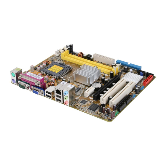
Page 19: Motherboard Layout
T: Mouse B: Keyboard ATX12V LGA775 BIOS USB34 Intel MCH 945GC LAN_USB12 RTM876-660 AUDIO CR2032 3V PCIEX1_1 Lithium Cell CMOS Power PCIEX1_16 SB_PWR Super I/O PCI1 Intel ICH7 PCI2 ALC662 SPDIF_OUT PS2_USBPWR FLOPPY AAFP USB78 USB56 SATA1 SATA2 ASUS P5GC-MX/GBL... -
Page 20: Central Processing Unit (Cpu)
Contact your retailer immediately if the PnP cap is missing, or if you see any damage to the PnP cap/socket pins/motherboard components. ASUS will shoulder the cost of repair only if the damage is shipment/transit-related. - Page 21 (B). Load plate Position the CPU over the socket, making sure that the gold triangle is on the bottom-left corner of the socket. The socket alignment key should fit into Alignment key the CPU notch. Gold triangle mark ASUS P5GC-MX/GBL...
- Page 22 Close the load plate (A), then push the load lever (B) until it snaps into the retention tab. The CPU fits in only one correct orientation. DO NOT force the CPU into the socket to prevent bending the connectors on the socket and damaging the CPU! The motherboard supports Intel LGA775 processors with the Intel Enhanced...
-
Page 23: Installling The Cpu Heatsink And Fan
Place the heatsink on top of the installed CPU, making sure that the four fasteners match the holes on the motherboard. Fastener Motherboard hole Make sure each fastener is oriented as shown, with the narrow groove directed outward. ASUS P5GC-MX/GBL 1-11... - Page 24 Push down two fasteners at a time in a diagonal sequence to secure the heatsink and fan assembly in place. When the fan and heatsink assembly is in place, connect the CPU fan cable to the connector on the motherboard labeled CPU_FAN. CPU_FAN +12V CPU FAN IN...
-
Page 25: Uninstalling The Cpu Heatsink And Fan
To uninstall the CPU heatsink and fan: Disconnect the CPU fan cable from the connector on the motherboard. Rotate each fastener counterclockwise. Pull up two fasteners at a time in a diagonal sequence to disengage the heatsink and fan assembly from the motherboard. ASUS P5GC-MX/GBL 1-13... - Page 26 Remove the heatsink and fan assembly from the motherboard. Rotate each fastener clockwise to reset the orientation. Narrow end of the groove The narrow end of the groove should point outward after resetting. (The photo shows the groove shaded for emphasis.) 1-14 Chapter 1: Product introduction...
-
Page 27: System Memory
240-pin footprint compared to the 184-pin DDR DIMM. DDR2 DIMMs are notched differently to prevent installation on a DDR DIMM socket. The figure illustrates the location of the DDR2 DIMM sockets: P5GC-MX/1333 240-pin DDR2 DIMM Sockets Channel Sockets Channel A DIMM_A1 Channel B DIMM_B1 ASUS P5GC-MX/GBL 1-15... -
Page 28: Memory Configurations
DDR2 Qualified Vendors List The following table lists the memory modules that have been tested and qualified for use with this motherboard. Visit the ASUS website (www.asus.com) for the latest DDR2 DIMM modules for this motherboard. Make sure to choose the right QVLs (Qualified Vendors List) from ASUS website according to the version of your mother board. - Page 29 TMS51B264C081-534QI takeMS MS18T51280-3.7 • • 512MB TAKEMS TMS51B264C081-534AP takeMS MS18T51280-3.7P0704D • • 512MB TAKEMS TMS51B264C081-534AE takeMS MS18T51280-3.7EA07100 • • TAKEMS TMS1GB264C081-534AE takeMS MS18T51280-3.7EA0651D • • TAKEMS TMS1GB264C081-534QI takeMS MS18T51280-3.7 • • TAKEMS TMS1GB264C081-534AP takeMS MS18T51280-3.7P0645D • • ASUS P5GC-MX/GBL 1-17...
- Page 30 DDR2 667 Qualified Vendors List DIMM support Size Vendor Model Brand Side(s) Part No. 256MB Kingston KVR667D2N5/256 Elpida E2508AB-6E-E • • 512MB Kingston KVR667D2N5/512 Kingston D6408TE8WL-27 • • Kingston KVR667D2N5/1G Kingston D6408TE8WL-3 • • 512MB Samsung KR M378T6553CZ0-CE6 Samsung K4T51083QC •...
-
Page 31: Memory Configuration
B*: - supports one pair of modules inserted into the yellow slots as one pair of Dual-channel memory configuration. Visit the ASUS website (www.asus.com) for the latest memory Qualified Vendor List (QVL). Make sure to choose the right QVLs according to the version of your mother board. -
Page 32: Installing A Dimm
1.7.4 Installing a DIMM Unplug the power supply before adding or removing DIMMs or other system components. Failure to do so can cause severe damage to both the motherboard and the components. To install a DIMM: DDR2 DIMM notch Unlock a DIMM socket by pressing the retaining clips outward. -
Page 33: Expansion Slots
Turn on the system and change the necessary BIOS settings, if any. See Chapter 2 for information on BIOS setup. Assign an IRQ to the card. Refer to the tables on the next page. Install the software drivers for the expansion card. ASUS P5GC-MX/GBL 1-21... -
Page 34: Interrupt Assignments
1.8.3 Interrupt assignments Standard interrupt assignments Standard Function System Timer Keyboard Controller Re-direct to IRQ#9 Communications Port (COM1)* IRQ holder for PCI steering* Floppy Disk Controller Printer Port (LPT1)* System CMOS/Real Time Clock IRQ holder for PCI steering* IRQ holder for PCI steering* IRQ holder for PCI steering* PS/2 Compatible Mouse Port* Numeric Data Processor... -
Page 35: Pci Slots
The figure shows a network card installed on the PCI Express x1 slot. 1.8.6 PCI Express x16 This motherboard supports one PCI Express x16 graphics card. The figure shows a graphics card installed on the PCI Express x16 slot. ASUS P5GC-MX/GBL 1-23... -
Page 36: Jumpers
Jumpers Clear RTC RAM (CLRTC) This jumper allows you to clear the Real Time Clock (RTC) RAM in CMOS. You can clear the CMOS memory of date, time, and system setup parameters by erasing the CMOS RTC RAM data. The onboard button cell battery powers the RAM data in CMOS, which include system setup information such as system passwords. -
Page 37: Usb Device Wake-Up
ATX power supply that can supply at least 500 mA on the +5VSB lead, and a corresponding setting in the BIOS. PS2_USBPWR P5GC-MX/GBL USB Device Wake Up The total current consumed must NOT exceed the power supply capability (+5VSB) whether under normal condition or in sleep mode. ASUS P5GC-MX/GBL 1-25... -
Page 38: 1.10 Connectors
1.10 Connectors 1.10.1 Rear panel connectors PS/2 mouse port (green). This port is for a PS/2 mouse. Parallel port. This 25-pin port connects a parallel printer, a scanner, or other devices. LAN (RJ-45) port. This port allows Gigabit connection to a Local Area Network (LAN) through a network hub. -
Page 39: Internal Connectors
Pin 5 on the connector is removed to prevent incorrect cable connection when using an FDD cable with a covered Pin 5. FLOPPY PIN1 NOTE: Orient the red markings on the floppy ribbon cable to PIN 1. Floppy Disk Drive Connector P5GC-MX/GBL ASUS P5GC-MX/GBL 1-27... - Page 40 IDE connectors (40-1 pin PRI_IDE) The onboard IDE connectors are for Ultra DMA 100/66/33 signal cables. There are three connectors on each Ultra DMA 100/66/33 signal cable: blue, black, and gray. Connect the blue connector to the motherboard’s IDE connector, then select one of the following modes to configure your device(s). IDE Connector P5GC-MX/GBL Drive jumper setting...
-
Page 41: Serial Ata Connectors
Boot disk SATA3/4 Black Slave Data Disk Speaker connector (4-pin SPEAKER) This 4-pin connector is for the chasis-mounted system warning speaker. The speaker allows you to hear system beeps and warnings. SPEAKER Speaker Out P5GC-MX/GBL Speaker Connectors ASUS P5GC-MX/GBL 1-29... - Page 42 CPU and Chassis fan connectors (4-pin CPU_FAN, 3-pin CHA_FAN) The fan connectors support cooling fans of a total of 1A~2.2A (26.4W max.) at +12V. Connect the fan cables to the fan connectors on the motherboard, making sure that the black wire of each cable matches the ground pin of the connector.
-
Page 43: Atx Power Connectors
+5 Volts +12 Volts +5 Volts +5V Standby +5 Volts Power OK -5 Volts Ground Ground +5 Volts Ground Ground Ground +5 Volts PSON# Ground Ground +3 Volts -12 Volts P5GC-MX/GBL ATX Power Connector +3 Volts +3 Volts ASUS P5GC-MX/GBL 1-31... - Page 44 Optical drive audio connector (4-pin CD) This connector allows you to receive stereo audio input from sound sources such as a CD-ROM, TV tuner, or MPEG card. (black) P5GC-MX/GBL Internal Audio Connector Enable the CD-IN function in the audio utility when using this connector. USB connectors (10-1 pin USB56, USB78) These connectors are for USB 2.0 ports.
-
Page 45: Chassis Intrusion Connector
By default, the pins labeled “Chassis Signal” and “Ground” are shorted with a jumper cap. Remove the jumper caps only when you intend to use the chassis intrusion detection feature. CHASSIS (Default) Chassis Signal +5VSB_MB P5GC-MX/GBL Intrusion Connector ASUS P5GC-MX/GBL 1-33... -
Page 46: System Panel Connector (10-1 Pin Panel)
12. System panel connector (10-1 pin F_PANEL) This connector supports several chassis-mounted functions. F_PANEL Reset Ground PLED- IDELED- PLED+ IDELED+ P5GC-MX/GBL System Panel Connector • System power LED (2-pin PWRLED) This 2-pin connector is for the system power LED. Connect the chassis power LED cable to this connector. -
Page 47: Chapter 2: Bios Setup
This chapter tells how to change the system settings through the BIOS Setup menus. Detailed descriptions of the BIOS parameters are also provided. BIOS setup... -
Page 48: Managing And Updating Your Bios
The following utilities allow you to manage and update the motherboard Basic Input/Output System (BIOS) setup. ASUS EZ Flash 2 (Updates the BIOS in DOS mode using a floppy disk or USB flash disk.) ASUS AFUDOS (Updates the BIOS in DOS mode using a bootable floppy disk.) -
Page 49: Asus Ez Flash 2 Utility
2.1.2 ASUS EZ Flash 2 utility The ASUS EZ Flash 2 feature allows you to update the BIOS without having to go through the long process of booting from a floppy disk and using a DOS-based utility. The EZ Flash 2 utility is built-in the BIOS chip so it is accessible by pressing <Alt>... -
Page 50: Afudos Utility
(2) Enter BIOS setup program. Go to the Tools menu then select EZ Flash2 and press <Enter>. You can switch between drives by pressing <Tab> before the correct file is found. Then press <Enter>. When the correct BIOS file is found, EZ Flash 2 performs the BIOS update process and automatically reboots the system when done. -
Page 51: Updating The Bios File
Visit the ASUS website (www.asus.com) and download the latest BIOS file for the motherboard. Save the BIOS file to a bootable floppy disk. Make sure to choose the right BIOS files from ASUS website according to the version of your mother board. Refer to your Printed Circuit Board (PCB) for version information. -
Page 52: Asus Crashfree Bios 3 Utility
2.1.4 ASUS CrashFree BIOS 3 utility The ASUS CrashFree BIOS 3 is an auto recovery tool that allows you to restore the BIOS file when it fails or gets corrupted during the updating process. You can update a corrupted BIOS file using the motherboard support CD , the floppy disk or the USB flash disk that contains the updated BIOS file. -
Page 53: Recovering The Bios From The Support Cd
BIOS file. The utility then updates the corrupted BIOS file. Bad BIOS checksum. Starting BIOS recovery... Checking for floppy... Floppy not found! Checking for CD-ROM... CD-ROM found! Reading file “P5GCMXGB.ROM”. Completed. Start flashing... ASUS P5GC-MX/GBL... -
Page 54: Recovering The Bios From The Usb Flash Disk
Restart the system after the utility completes the updating process. • Only the USB flash disk with FAT 32/16 format and single partition can support ASUS CrashFree BIOS 3. The device size should be smaller than 8GB. • DO NOT shut down or reset the system while updating the BIOS! Doing so... -
Page 55: Asus Update Utility
2.1.5 ASUS Update utility The ASUS Update is a utility that allows you to manage, save, and update the motherboard BIOS in Windows environment. The ASUS Update utility allows you ® • Save the current BIOS file • Download the latest BIOS file from the Internet •... - Page 56 To update the BIOS through the Internet: desktop by clicking Start Launch the ASUS Update utility from the Windows ® > Programs > ASUS > ASUSUpdate > ASUSUpdate. The ASUS Update main window appears. Select Update BIOS from Select the ASUS FTP site nearest...
- Page 57 To update the BIOS through a BIOS file: desktop by clicking Start Launch the ASUS Update utility from the Windows ® > Programs > ASUS > ASUSUpdate > ASUSUpdate. The ASUS Update main window appears. Select Update BIOS from a file option from the drop-down menu, then click Next.
-
Page 58: Bios Setup Program
• Visit the ASUS website (www.asus.com) to download the latest BIOS file for this motherboard. Make sure to choose the right BIOS files according to the version of your mother board. Refer to your Printed Circuit Board (PCB) for version information. -
Page 59: Bios Menu Screen
At the bottom right corner of a menu screen are the navigation keys for that particular menu. Use the navigation keys to select items in the menu and change the settings. Some of the navigation keys differ from one screen to another. ASUS P5GC-MX/GBL 2-13... -
Page 60: Menu Items
2.2.4 Menu items The highlighted item on the menu bar BIOS SETUP UTILITY Main Advanced Power Boot Tools Exit displays the specific items for that menu. System Time [19:34:30] Use [ENTER], [TAB] or System Date [Mon 11/19/2007] Legacy Diskette A [1.44M, 3.5 in] [SHIFT-TAB] to select For example, selecting Main shows the Main... -
Page 61: Main Menu
Allows you to set the system date. 2.3.3 Legacy Diskette A [1.44M, 3.5 in.] Sets the type of floppy drive installed. Configuration options: [Disabled] [360K, 5.25 in.] [1.2M , 5.25 in.] [720K , 3.5 in.] [1.44M, 3.5 in.] [2.88M, 3.5 in.] ASUS P5GC-MX/GBL 2-15... -
Page 62: Primary, Third And Fourth Ide Master/Slave
2.3.4 Primary, Third and Fourth IDE Master/Slave While entering Setup, the BIOS automatically detects the presence of IDE devices. There is a separate sub-menu for each IDE device. Select a device item then press <Enter> to display the IDE device information. Primary IDE Master Select the type of device connected... -
Page 63: Ide Configuration
Disables or allows selection of the IDE operation mode depending on the operating system (OS) that you installed. Set to Enhanced Mode if you are using native OS, such as Windows 2000/XP/Vista. ® Configuration options: [Disabled] [Compatible Mode] [Enhanced Mode] ASUS P5GC-MX/GBL 2-17... -
Page 64: System Information
Enhanced Mode Support On [S-ATA] The default setting S-ATA allows you to use native OS on Serial ATA and Parallel ATA ports. We recommend that you do not change the default setting for better OS compatibility. In this setting, you may use legacy OS on the Parallel ATA ports only if you did not install any Serial ATA device. -
Page 65: Advanced Menu
AI Overclocking [Auto] Allows selection of CPU frequency and auto adjustment of relevant parameters. Frequencies higher than CPU manufacturer recommends are not guaranteed to be stable. If the system becomes unstable, return to the default. Configuration options: [Manual] [Auto] ASUS P5GC-MX/GBL 2-19... - Page 66 The following item appears only when you set the AI Overclocking item to [Manual]. CPU Frequency [XXX] Displays the frequency sent by the clock generator to the system bus and PCI bus. The value of this item is auto-detected by the BIOS. Use the <+> and <-> keys to adjust the CPU frequency.
-
Page 67: Usb Configuration
Allows you to configure the USB 2.0 controller in HiSpeed (480 Mbps) or Full Speed (12 Mbps). Configuration options: [FullSpeed] [HiSpeed] BIOS EHCI Hand-Off [Enabled] Allows you to enable support for operating systems without an EHCI hand-off feature. Configuration options: [Disabled] [Enabled] ASUS P5GC-MX/GBL 2-21... -
Page 68: Cpu Configuration
2.4.3 CPU Configuration The items in this menu show the CPU-related information that the BIOS automatically detects. BIOS SETUP UTILITY Advanced Configure advanced CPU settings Options Manufacturer: Intel Brand String: Intel(R) Core(TM)2 Duo CPU @ 1.86GHz Auto Frequency : 1.86MHz Manual FSB Speed : 1066MHz... -
Page 69: Chipset
PEG Buffer Length [Auto] Exit Link Latency [Auto] PEG Root Control [Auto] Enter Go to Sub Screen Slot Power [Auto] General Help High Priority Port Select [Disabled] Save and Exit Exit v02.58 (C)Copyright 1985-2007, American Megatrends, Inc. ASUS P5GC-MX/GBL 2-23... - Page 70 Configure DRAM Timing by SPD [Enabled] When this item is enabled, the DRAM timing parameters are set according to the DRAM SPD (Serial Presence Detect). When disabled, you can manually set the DRAM timing parameters through the DRAM sub-items. The following sub-items appear when this item is Disabled.
- Page 71 Enables, disables or set to Auto of the link latency. Configuration options: [Auto] [Disabled] [Enabled] Slot Power [Auto] Sets the slot power. Configuration options: [Auto] [Light] [Normal] [Heavy] [Heavier] High Priority Port Select [Disabled] Selects the high priority port. Configuration options: [Disabled] [PCI Express Port 2] ASUS P5GC-MX/GBL 2-25...
-
Page 72: Onboard Devices Configuration
2.4.5 Onboard Devices Configuration Configure Win627DHG Super IO Chipset Enable or Disable HD Audio Controller [Enabled] High Definition Audio Front Panel Support Type [HD Audio] Controller Onboard PCIEX Gigabit LAN [Enabled] LAN Option ROM [Disabled] Serial Port1 Address [3F8/IRQ4] Parallel Port Address [378] Parallel Port Mode [ECP]... -
Page 73: Pci Pnp
Plug and Play devices not required for boot. Configuration options: [No] [Yes] PCI Latency Timer [64] Allows you to select the value in units of PCI clocks for the PCI device latency timer register. Configuration options: [32] [64] [96] [128] [160] [192] [224] [248] ASUS P5GC-MX/GBL 2-27... - Page 74 Allocate IRQ to PCI VGA [Yes] When set to [Yes], BIOS assigns an IRQ to PCI VGA card if the card requests for an IRQ. When set to [No], BIOS does not assign an IRQ to the PCI VGA card even if requested.
-
Page 75: Power Menu
Allows you to enable or disable the Advanced Configuration and Power Interface (ACPI) support in the Application-Specific Integrated Circuit (ASIC). When set to Enabled, the ACPI APIC table pointer is included in the RSDT pointer list. Configuration options: [Disabled] [Enabled] ASUS P5GC-MX/GBL 2-29... -
Page 76: Apm Configuration
2.5.4 APM Configuration BIOS SETUP UTILITY Power APM Configuration Go into On/Off or Suspend when Power button is pressed. Restore on AC Power Loss [Power Off] Power On By RTC Alarm [Disabled] Power On By External Modems [Disabled] Power On By PCI Devices [Disabled] Power On By PCIE Devices [Disabled]... - Page 77 When set to [Enabled], this parameter allows you to use the PS/2 mouse to turn on the system. This feature requires an ATX power supply that provides at least 1A on the +5VSB lead. Configuration options: [Disabled] [Enabled] ASUS P5GC-MX/GBL 2-31...
-
Page 78: Hardware Monitor
N/A. Configuration options: [Ignored] [xxxRPM] CPU Q-Fan Control [Disabled] Allows you to enable or disable the ASUS Q-Fan feature that smartly adjusts the fan speeds for more efficient system operation. Configuration options: [Disabled] [Enabled] Chassis Fan Speed [xxxxRPM] or [N/A] or [Ignored] The onboard hardware monitor automatically detects and displays the chassis fan speed in rotations per minute (RPM). -
Page 79: Boot Menu
These items specify the boot device priority sequence from the available devices. The number of device items that appears on the screen depends on the number of devices installed in the system. Configuration options: [xxxxx Drive] [ATAPI CD-ROM] [Disabled] ASUS P5GC-MX/GBL 2-33... -
Page 80: Boot Settings Configuration
This allows you to enable or disable the full screen logo display feature. Configuration options: [Disabled] [Enabled] Set this item to [Enabled] to use the ASUS MyLogo2™ feature. Add On ROM Display Mode [Force BIOS] Sets the display mode for option ROM. -
Page 81: Security
<Enter>. The message “Password Uninstalled” appears. If you forget your BIOS password, you can clear clear it by erasing the CMOS Real Time Clock (RTC) RAM. See section “1.9 Jumpers” for information on how to erase the RTC RAM. ASUS P5GC-MX/GBL 2-35... -
Page 82: Change User Password
After you have set a supervisor password, the other items appear to allow you to change other security settings. Security Settings Supervisor Password : Not Installed User Password : Not Installed Change Supervisor Password User Access Level [Full Access] Change User Password Clear User Password Password Check [Setup]... -
Page 83: Tools Menu
(C)Copyright 1985-2007, American Megatrends, Inc. ASUS EZ Flash 2 Allows you to run ASUS EZ Flash 2. When you press <Enter>, a confirmation message appears. Use the left/right arrow key to select between [Yes] or [No], then press <Enter> to confirm your choice. See section 2.1.2 for details. -
Page 84: Exit Menu
• This function can not support IDE CD-ROM, IDE DVD-ROM, or External SATA devices. • This function only supports FAT 32/16 format. Exit menu The Exit menu items allow you to load the optimal or failsafe default values for the BIOS items, and save or discard your changes to the BIOS items. -
Page 85: Discard Changes
Setup menus. When you select this option or if you press <F5>, a confirmation window appears. Select Ok to load default values. Select Exit & Save Changes or make other changes before saving the values to the non-volatile RAM. ASUS P5GC-MX/GBL 2-39... - Page 86 2-40 Chapter 2: BIOS setup...
-
Page 87: Chapter 3: Software Support
This chapter describes the contents of the support CD that comes with the motherboard package. Software support... -
Page 88: Installing An Operating System
The contents of the support CD are subject to change at any time without notice. Visit the ASUS website(www.asus.com) for updates. 3.2.1 Running the support CD Place the support CD to the optical drive. The CD automatically displays the Drivers menu if Autorun is enabled in your computer. -
Page 89: Drivers Menu
The drivers menu shows the available device drivers if the system detects installed devices. Install the necessary drivers to activate the devices. ASUS InstAll - Installation Wizard for Drivers Launches the ASUS InstallAll driver installation wizard. Intel Chipset Inf Update Program This item installs the Intel Chipset INF Update Program. -
Page 90: Utilities Menu
ASUS InstAll - Installation Wizard for Utilities Launches the ASUS InstallAll utilities installation wizard. ASUS Update The ASUS Update utility allows you to update the motherboard BIOS in a Windows environment. This utility requires an Internet connection either through a ®... - Page 91 TV and movies, capturing videos, or playing games in your computer. Visit the Microsoft website (www.microsoft.com) for updates. ASUS Motherboard Installation Guide Click to open the ASUS Motherboard Installation Guide. The installation guide is in Portable Document Format (PDF). Install the Adobe...
-
Page 92: Asus Contact Information
3.2.4 ASUS Contact information Click the Contact tab to display the ASUS contact information. You can also find this information on the inside front cover of this user guide. Chapter 3: Software support... -
Page 93: Cpu Features
The Appendix describes the CPU features that the motherboard supports. CPU features... -
Page 94: Appendix: Cpu Features
32-bit operating systems. • The motherboard comes with a BIOS file that supports EM64T. You can download the latest BIOS file from the ASUS website (www.asus.com/ support/download/) if you need to update the BIOS file. • Visit www.intel.com for more information on the EM64T feature. -
Page 95: Using The Eist
Click Apply, then click OK. 10. Close the Display Properties window. After you adjust the power scheme, the CPU internal frequency slightly decreases when the CPU loading is low. The screen displays and procedures may vary depending on the operating system. ASUS P5GC-MX/GBL... -
Page 96: Intel ® Hyper-Threading Technology
Intel Hyper-Threading Technology ® • The motherboard supports Intel Pentium 4 LGA775 processors with ® ® Hyper-Threading Technology. • Hyper-Threading Technology is supported under Windows XP and Linux ® 2.4.x (kernel) and later versions only. Under Linux, use the Hyper- Threading compiler to compile the code.