Table of Contents
Advertisement
Advertisement
Table of Contents

Related Manuals for Asus P5GD1-VM


Summary of Contents for Asus P5GD1-VM
- Page 1 P5GD1-VM...
- Page 2 Product warranty or service will not be extended if: (1) the product is repaired, modified or altered, unless such repair, modification of alteration is authorized in writing by ASUS; or (2) the serial number of the product is defaced or missing.
-
Page 3: Table Of Contents
Contents Notices ....................vi Safety information ................vii P5GD1-VM specifications summary ..........viii Chapter 1: Chapter 1: Chapter 1: Product introduction Product introduction Product introduction Chapter 1: Chapter 1: Product introduction Product introduction Welcome! ................1-2 Package contents ..............1-2 Special features .............. - Page 4 Creating a bootable floppy disk ......2-2 2.1.2 AFUDOS utility ............2-3 2.1.3 ASUS EZ Flash utility ..........2-5 2.1.4 ASUS CrashFree BIOS 2 utility ........ 2-7 2.1.5 ASUS Update utility ..........2-9 BIOS setup program ............2-12 2.2.1 BIOS menu screen ..........2-13 2.2.2...
- Page 5 Support CD information ............3-2 3.2.1 Running the support CD ......... 3-2 3.2.2 Drivers menu ............3-3 3.2.3 Utilities menu ............3-4 3.2.4 ASUS Contact information ........3-5 3.2.5 Other information ........... 3-6 Appendix: Appendix: CPU features CPU features Appendix:...
-
Page 6: Notices
Notices Federal Communications Commission Statement Federal Communications Commission Statement Federal Communications Commission Statement Federal Communications Commission Statement Federal Communications Commission Statement This device complies with Part 15 of the FCC Rules. Operation is subject to the following two conditions: • This device may not cause harmful interference, and •... -
Page 7: Safety Information
Safety information Electrical safety Electrical safety Electrical safety Electrical safety Electrical safety • To prevent electrical shock hazard, disconnect the power cable from the electrical outlet before relocating the system. • When adding or removing devices to or from the system, ensure that the power cables for the devices are unplugged before the signal cables are connected. -
Page 8: P5Gd1-Vm Specifications Summary
P5GD1-VM specifications summary C P U C P U C P U LGA775 socket for Intel ® Pentium ® 4/Celeron processor C P U C P U Compatible with Intel ® PCG 04A and 04B processors Supports Intel ® Hyper-Threading Technology Supports Intel ®... - Page 9 P5GD1-VM specifications summary R e a r p a n e l R e a r p a n e l R e a r p a n e l 1 x PS/2 mouse port R e a r p a n e l...
- Page 10 x x x x x...
- Page 11 This chapter describes the motherboard features and the new technologies it supports. Product introduction...
-
Page 12: Welcome
P 5 G D 1 - V M m o t h e r b o a r d ! The motherboard delivers a host of new features and latest technologies, making it another standout in the long line of ASUS quality motherboards! Before you start installing the motherboard, and hardware devices on it, check the items in your package with the list below. - Page 13 Dual display technology support (optional) The integrated graphics engine supports dual display technology and TV out function through the optional ASUS DVI-ADD2 card. You can show additional independent display on an LCD monitor, or stretch one type of content on both VGA and LCD monitors for more workspace. See page 1-20 for details.
-
Page 14: Innovative Asus Features
ASUS EZ Flash BIOS ASUS EZ Flash BIOS With the ASUS EZ Flash, you can easily update the system BIOS even before loading the operating system. No need to use a DOS-based utility or boot from a floppy disk. See page 2-5 for details. -
Page 15: Before You Proceed
The illustration below shows the location of the onboard LED. SB_PWR1 ® Standby Powered P5GD1-VM Onboard LED Power A S U S P 5 G D 1 - V M A S U S P 5 G D 1 - V M 1 - 5 1 - 5... -
Page 16: Motherboard Overview
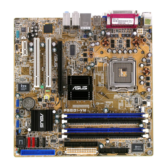
Motherboard overview 1.5.1 1.5.1 1.5.1 1.5.1 1.5.1 Motherboard layout Motherboard layout Motherboard layout Motherboard layout Motherboard layout KBPWR1 PS/2KBMS CHA_FAN1 T: Mouse B: Keyboard CPU_FAN1 COM1 ATX12V1 FANPWR1 LGA775 VGA1 F_USB12 LAN_USB34 Intel Top:Rear Speaker Out 915G Center: Side Speaker Out Below: Center/Subwoofer Top:Line In... -
Page 17: Placement Direction
1.5.2 1.5.2 1.5.2 Placement direction Placement direction Placement direction 1.5.2 1.5.2 Placement direction Placement direction When installing the motherboard, make sure that you place it into the chassis in the correct orientation. The edge with external ports goes to the rear part of the chassis as indicated in the image below. -
Page 18: Central Processing Unit (Cpu)
Contact your retailer immediately if the PnP cap is missing, or if you see any damage to the PnP cap/socket contacts/motherboard components. ASUS will shoulder the cost of repair only if the damage is shipment/ transit-related. •... - Page 19 Press the load lever with your thumb (A), then move it to the left (B) until it is released from the retention tab. R e t e n t i o n t a b R e t e n t i o n t a b R e t e n t i o n t a b R e t e n t i o n t a b R e t e n t i o n t a b...
- Page 20 The CPU fits in only one correct orientation. DO NOT force the CPU into the socket to prevent bending the connectors on the socket and damaging the CPU! Close the load plate (A), then push the load lever (B) until it snaps into the retention tab.
-
Page 21: Installing The Cpu Heatsink And Fan
1.6.2 1.6.2 Installing the CPU heatsink and fan Installing the CPU heatsink and fan 1.6.2 1.6.2 1.6.2 Installing the CPU heatsink and fan Installing the CPU heatsink and fan Installing the CPU heatsink and fan The Intel ® Pentium ® 4 LGA775 processor requires a specially designed heatsink and fan assembly to ensure optimum thermal condition and performance. - Page 22 Push down two fasteners at a time in a diagonal sequence to secure the heatsink and fan assembly in place. Connect the CPU fan cable to the connector on the motherboard labeled CPU_FAN1. CPU_FAN1 ® Do not forget to connect the CPU fan connector! Hardware monitoring errors can occur if you fail to plug this connector.
-
Page 23: Uninstalling The Cpu Heatsink And Fan
1.6.3 1.6.3 1.6.3 Uninstalling the CPU heatsink and fan Uninstalling the CPU heatsink and fan Uninstalling the CPU heatsink and fan 1.6.3 1.6.3 Uninstalling the CPU heatsink and fan Uninstalling the CPU heatsink and fan To uninstall the CPU heatsink and fan: Disconnect the CPU fan cable from the connector on the motherboard. - Page 24 Carefully remove the heatsink and fan assembly from the motherboard. Rotate each fastener clockwise to ensure correct orientation when reinstalling. N a r r o w e n d o f t h e g r o o v e N a r r o w e n d o f t h e g r o o v e N a r r o w e n d o f t h e g r o o v e N a r r o w e n d o f t h e g r o o v e...
-
Page 25: System Memory
Inline Memory Modules (DIMM) sockets. The following figure illustrates the location of the sockets: ® P5GD1-VM 184-Pin DDR DIMM Sockets C h a n n e l C h a n n e l C h a n n e l... - Page 26 Dual-channel memory configuration. C C C C C - supports four modules inserted into the blue and black slots as two pairs of Dual-channel memory configuration. Visit the ASUS website (www.asus.com) for the latest DDR Qualified Vendors List. 1 - 1 6...
-
Page 27: Installing A Dimm
1.7.3 1.7.3 1.7.3 Installing a DIMM Installing a DIMM Installing a DIMM 1.7.3 1.7.3 Installing a DIMM Installing a DIMM Make sure to unplug the power supply before adding or removing DIMMs or other system components. Failure to do so may cause severe damage to both the motherboard and the components. -
Page 28: Expansion Slots
Expansion slots In the future, you may need to install expansion cards. The following sub-sections describe the slots and the expansion cards that they support. Make sure to unplug the power cord before adding or removing expansion cards. Failure to do so may cause you physical injury and damage motherboard components. - Page 29 Standard interrupt assignments Standard interrupt assignments Standard interrupt assignments Standard interrupt assignments Standard interrupt assignments I R Q I R Q I R Q I R Q I R Q P r i o r i t y P r i o r i t y P r i o r i t y P r i o r i t y P r i o r i t y...
-
Page 30: Pci Slots
1.8.3 1.8.3 PCI slots PCI slots 1.8.4 1.8.4 1.8.4 PCI Express x1 PCI Express x1 PCI Express x1 1.8.3 1.8.3 1.8.3 PCI slots PCI slots PCI slots 1.8.4 1.8.4 PCI Express x1 PCI Express x1 slot slot slot slot slot The PCI slots support cards such as a LAN card, SCSI card, USB card, This motherboard supports PCI... -
Page 31: Jumpers
Removing the cap will cause system boot failure! CLRTC1 ® Normal Clear CMOS P5GD1-VM Clear RTC RAM (Default) A S U S P 5 G D 1 - V M A S U S P 5 G D 1 - V M 1 - 2 1... - Page 32 +5VSB (Default) USBPW56 USBPW78 ® +5VSB P5GD1-VM USB device wake-up (Default) • The USB device wake-up feature requires a power supply that can provide 500mA on the +5VSB lead for each USB port; otherwise, the system will not power up.
-
Page 33: 1.10 Connectors
Set this jumper to 1-2 (Default) if you are using a 4-pin CPU fan. Set this jumper to 2-3 if you are using a 3-pin CPU fan. FANPWR1 DC mode (Default) ® P5GD1-VM FAN power setting We recommend the use of a 4-pin CPU fan. 1.10 Connectors 1.10.1 1.10.1 1.10.1 Rear panel connectors... - Page 34 4 . 4 . R e a r S p e a k e r O u t p o r t ( g r a y ) . R e a r S p e a k e r O u t p o r t ( g r a y ) . R e a r S p e a k e r O u t p o r t ( g r a y ) .
-
Page 35: Internal Connectors
® PIN 1 P5GD1-VM Floppy disk drive connector 2 . 2 . P r i m a r y I D E c o n n e c t o r ( 4 0 - 1 p i n P R I _ I D E 1 ) - Page 36 PRI_PCIIDE1 NOTE: Orient the red markings (usually zigzag) on the IDE cable to PIN 1. ® P5GD1-VM PCI IDE connector • The system automatically assigns the boot sequence of ATAPI devices connected to the PCI IDE connector. • The ITE ®...
-
Page 37: Hard Disk Drives
SATA3 ® SATA2 P5GD1-VM SATA connectors SATA1 I m p o r t a n t n o t e s o n S e r i a l A T A I m p o r t a n t n o t e s o n S e r i a l A T A... - Page 38 These are not jumpers! Do not place jumper caps on the fan connectors! CHA_FAN1 CPU_FAN1 ® P5GD1-VM Fan connectors Make sure that your Fan Power (FANPWR1) jumper setting is correct. See page 1-22 for details. 1 - 2 8 1 - 2 8...
- Page 39 ® USB56 USB78 P5GD1-VM USB 2.0 connectors Never connect a 1394 cable to the USB connectors. Doing so will damage the motherboard! The USB module is purchased separately. A S U S P 5 G D 1 - V M...
- Page 40 +5 Volts PSON# Ground Ground +3 Volts -12 Volts P5GD1-VM ATX power connectors +3 Volts +3 Volts Important notes on the motherboard power requirements Important notes on the motherboard power requirements Important notes on the motherboard power requirements Important notes on the motherboard power requirements Important notes on the motherboard power requirements •...
- Page 41 AAFP1 ® P5GD1-VM Analog front panel connector We recommend that you connect a high-definition front panel audio module to this connector to use the high-definition audio features of the motherboard. A S U S P 5 G D 1 - V M...
-
Page 42: Chassis Intrusion Connector
CHASSIS1 ® (Default) P5GD1-VM Chassis intrusion connector 1 1 . 1 1 . 1 1 . S p e a k e r O u t c o n n e c t o r ( 4 - p i n S P E A K E R 1 ) -
Page 43: Digital Audio Connector
® SPDIF_OUT1 P5GD1-VM Digital audio connector P o w e r L E D L e a d ( 3 - 1 p i n P L E D 1 ) P o w e r L E D L e a d ( 3 - 1 p i n P L E D 1 ) -
Page 44: System Panel Connector
IDE LED RESET Requires an ATX power supply. P5GD1-VM System panel connector The sytem panel connector is color-coded for easy connection. Refer to the connector description below for details. H a r d d i s k d r i v e a c t i v i t y L E D ( R e d 2 - p i n I D E L E D ) H a r d d i s k d r i v e a c t i v i t y L E D ( R e d 2 - p i n I D E L E D ) •... - Page 45 This chapter tells how to change the system settings through the BIOS Setup menus. Detailed descriptions of the BIOS parameters are also provided. BIOS setup A S U S P 5 G D 1 - V M A S U S P 5 G D 1 - V M A S U S P 5 G D 1 - V M 2 - 1 2 - 1...
-
Page 46: Managing And Updating Your Bios
Refer to the corresponding sections for details on these utilities. Save a copy of the original motherboard BIOS file to a bootable floppy disk in case you need to restore the BIOS in the future. Copy the original motherboard BIOS using the ASUS Update or AFUDOS utilities. 2.1.1 2.1.1... -
Page 47: Afudos Utility
d. From the Open field, type D:\bootdisk\makeboot a: assuming that D: is your optical drive. e. Press <Enter>, then follow screen instructions to continue. Copy the original or the latest motherboard BIOS file to the bootable floppy disk. 2.1.2 2.1.2 AFUDOS utility AFUDOS utility 2.1.2... -
Page 48: Updating The Bios File
Updating the BIOS file To update the BIOS file using the AFUDOS utility: Visit the ASUS website (www.asus.com) and download the latest BIOS file for the motherboard. Save the BIOS file to a bootable floppy disk. Write the BIOS filename on a piece of paper. You need to type the exact BIOS filename at the DOS prompt. -
Page 49: Asus Ez Flash Utility
ASUS EZ Flash utility ASUS EZ Flash utility The ASUS EZ Flash feature allows you to update the BIOS without having to go through the long process of booting from a floppy disk and using a DOS-based utility. The EZ Flash utility is built-in the BIOS chip so it is accessible by pressing <Alt>... - Page 50 • A “Floppy not found!” error message appears if there is no floppy disk in the drive. A “P5GD1-VM.ROM not found!” error message appears if the correct BIOS file is not found in the floppy disk. Make sure that you rename the BIOS file to P5GD1-VM.ROM.
-
Page 51: Asus Crashfree Bios 2 Utility
ASUS CrashFree BIOS 2 utility ASUS CrashFree BIOS 2 utility The ASUS CrashFree BIOS 2 is an auto recovery tool that allows you to restore the BIOS file when it fails or gets corrupted during the updating process. You can update a corrupted BIOS file using the motherboard support CD or the floppy disk that contains the updated BIOS file. - Page 52 Restart the system after the utility completes the updating process. The recovered BIOS may not be the latest BIOS version for this motherboard. Visit the ASUS website (www.asus.com) to download the latest BIOS file. 2 - 8...
-
Page 53: Asus Update Utility
ASUS Update utility 2.1.5 2.1.5 ASUS Update utility ASUS Update utility The ASUS Update is a utility that allows you to manage, save, and update the motherboard BIOS in Windows ® environment. The ASUS Update utility allows you to: •... - Page 54 Updating the BIOS through the Internet Updating the BIOS through the Internet Updating the BIOS through the Internet To update the BIOS through the Internet: Launch the ASUS Update utility from the Windows ® desktop by clicking S t a r t...
- Page 55 A S U S U p d a t e > A S U S U p d a t e A S U S U p d a t e. The ASUS Update main window appears. A S U S U p d a t e...
-
Page 56: Bios Setup Program
The BIOS setup screens shown in this section are for reference purposes only, and may not exactly match what you see on your screen. • Visit the ASUS website (www.asus.com) to download the latest BIOS file for this motherboard. 2 - 1 2 2 - 1 2... -
Page 57: Bios Menu Screen
2.2.1 2.2.1 2.2.1 BIOS menu screen BIOS menu screen BIOS menu screen 2.2.1 2.2.1 BIOS menu screen BIOS menu screen M e n u i t e m s M e n u i t e m s M e n u i t e m s M e n u i t e m s M e n u i t e m s M e n u b a r... -
Page 58: Menu Items
2.2.4 2.2.4 2.2.4 Menu items Menu items Menu items 2.2.4 2.2.4 Menu items Menu items The highlighted item on the menu Use [ENTER], [TAB] bar displays the specific items for System Time [11:51:19] or [SHIFT-TAB] to System Date [Thu 06/10/2004] select a field. -
Page 59: Main Menu
Main menu When you enter the BIOS Setup program, the Main menu screen appears, giving you an overview of the basic system information. Refer to section “2.2.1 BIOS menu screen” for information on the menu screen items and how to navigate through them. Use [ENTER], [TAB] or System Time [11:51:19]... -
Page 60: Primary, Third, And Fourth Ide Master/Slave
2.3.4 2.3.4 2.3.4 Primary, Third, and Fourth IDE Master/Slave Primary, Third, and Fourth IDE Master/Slave Primary, Third, and Fourth IDE Master/Slave 2.3.4 2.3.4 Primary, Third, and Fourth IDE Master/Slave Primary, Third, and Fourth IDE Master/Slave While entering Setup, the BIOS automatically detects the presence of IDE devices. -
Page 61: Ide Configuration
PIO Mode [Auto] PIO Mode [Auto] PIO Mode [Auto] PIO Mode [Auto] PIO Mode [Auto] Selects the PIO mode. Configuration options: [Auto] [0] [1] [2] [3] [4] DMA Mode [Auto] DMA Mode [Auto] DMA Mode [Auto] DMA Mode [Auto] DMA Mode [Auto] Selects the DMA mode. -
Page 62: System Information
Enhanced Mode Support On [SATA mode] The default setting SATA allows you to use native OS on Serial ATA and Parallel ATA ports. We recommend that you do not change the default setting for better OS compatibility. In this setting, you may o n l y i f o n l y i f use legacy OS on the Parallel ATA ports o n l y i f... -
Page 63: Advanced Menu
Advanced menu The Advanced menu items allow you to change the settings for the CPU and other system devices. Take caution when changing the settings of the Advanced menu items. Incorrect field values can cause the system to malfunction. Configure the USB USB Configuration support. -
Page 64: Cpu Configuration
Legacy USB Support [Auto] Legacy USB Support [Auto] Legacy USB Support [Auto] Legacy USB Support [Auto] Legacy USB Support [Auto] Allows you to enable or disable support for USB devices on legacy operating systems (OS). Setting to Auto allows the system to detect the presence of USB devices at startup. - Page 65 Ratio CMOS Setting [ 8] Ratio CMOS Setting [ 8] Ratio CMOS Setting [ 8] Ratio CMOS Setting [ 8] Ratio CMOS Setting [ 8] Sets the ratio between the CPU Core Clock and the Front Side Bus frequency. The default value of this item is auto-detected by BIOS. Use the <...
-
Page 66: Chipset
The following item appears only when you installed an Intel ® Pentium ® CPU that supports the Enhanced Intel SpeedStep ® Technology (EIST). Intel(R) SpeedStep Technology [Automatic] Intel(R) SpeedStep Technology [Automatic] Intel(R) SpeedStep Technology [Automatic] Intel(R) SpeedStep Technology [Automatic] Intel(R) SpeedStep Technology [Automatic] Allows you to use the Enhanced Intel SpeedStep ®... - Page 67 Advanced Chipset Settings Advanced Chipset Settings Advanced Chipset Settings Advanced Chipset Settings Advanced Chipset Settings Configure DRAM Timing by SPD [Enabled] When this item is enabled, the DRAM timing parameters are set according to the DRAM SPD (Serial Presence Detect). When disabled, you can manually set the DRAM timing parameters through the DRAM sub-items.
-
Page 68: Onboard Devices Configuration
2.4.4 2.4.4 Onboard Devices Configuration Onboard Devices Configuration 2.4.4 2.4.4 2.4.4 Onboard Devices Configuration Onboard Devices Configuration Onboard Devices Configuration Configure Win627EHF Super IO Chipset Enable or disable Azalia controller. Azalia Controller [Enabled] Onboard LAN [Enabled] LAN Boot ROM [Disabled] ITE8211 Controller [Enabled] Detecting Device Time... -
Page 69: Pci Pnp
Parallel Port Address [378] Parallel Port Address [378] Parallel Port Address [378] Parallel Port Address [378] Parallel Port Address [378] Allows you to select the Parallel Port base addresses. Configuration options: [Disabled] [378] [278] [3BC] Parallel Port Mode [ECP] Parallel Port Mode [ECP] Parallel Port Mode [ECP] Parallel Port Mode [ECP] Parallel Port Mode [ECP]... - Page 70 Plug and Play O/S [No] Plug and Play O/S [No] Plug and Play O/S [No] Plug and Play O/S [No] Plug and Play O/S [No] When set to [No], BIOS configures all the devices in the system. When set to [Yes] and if you install a Plug and Play operating system, the operating system configures the Plug and Play devices not required for boot.
-
Page 71: Power Menu
Power menu The Power menu items allow you to change the settings for the Advanced Power Management (APM) and Advanced Configuration and Power Interface (ACPI). Select an item then press <Enter> to display the configuration options. Select the ACPI state Suspend Mode [Auto] used for System... -
Page 72: Apm Configuration
2.5.5 2.5.5 2.5.5 APM Configuration APM Configuration APM Configuration 2.5.5 2.5.5 APM Configuration APM Configuration APM Configuration <Enter> to select whether or not to Restore on AC Power Loss [Power Off] restart the system Power On By RTC Alarm [Disabled] after AC power loss. -
Page 73: Hardware Monitor
Power On By PS/2 Keyboard [Disabled] Power On By PS/2 Keyboard [Disabled] Power On By PS/2 Keyboard [Disabled] Power On By PS/2 Keyboard [Disabled] Power On By PS/2 Keyboard [Disabled] Allows you to use specific keys on the keyboard to turn on the system. This feature requires an ATX power supply that provides at least 1A on the +5VSB lead. - Page 74 CPU Q-Fan Control [Disabled] CPU Q-Fan Control [Disabled] Allows you to enable or disable the ASUS Q-Fan feature that smartly adjusts the fan speeds for more efficient system operation. When this field is set to [Enabled], the C P U F a n R a t i o...
-
Page 75: Boot Menu
Boot menu The Boot menu items allow you to change the system boot options. Select an item then press <Enter> to display the sub-menu. Boot Settings Specifies the Boot Device Priority Boot Device Priority sequence Boot Settings Configuration Security 2.6.1 2.6.1 2.6.1 Boot Device Priority... -
Page 76: Boot Settings Configuration
This allows you to enable or disable the full screen logo display feature. Configuration options: [Disabled] [Enabled] Set this item to [Enabled] to use the ASUS MyLogo™ feature. Add On ROM Display Mode [Force BIOS] Add On ROM Display Mode [Force BIOS]... -
Page 77: Security
Hit ‘DEL’ Message Display [Enabled] Hit ‘DEL’ Message Display [Enabled] Hit ‘DEL’ Message Display [Enabled] Hit ‘DEL’ Message Display [Enabled] Hit ‘DEL’ Message Display [Enabled] When set to Enabled, the system displays the message “Press DEL to run Setup” during POST. Configuration options: [Disabled] [Enabled] Interrupt 19 Capture [Disabled] Interrupt 19 Capture [Disabled] Interrupt 19 Capture [Disabled]... - Page 78 If you forget your BIOS password, you clear it by erasing the CMOS Real Time Clock (RTC) RAM. See section “1.9 Jumpers” for information on how to erase the RTC RAM. After you have set a supervisor password, the other items appear to allow you to change other security settings.
-
Page 79: Exit Menu
The message “Password Installed” appears after you set your password successfully. To change the user password, follow the same steps as in setting a user password. Clear User Password Clear User Password Clear User Password Clear User Password Clear User Password Select this item to clear the user password. - Page 80 Exit & Save Changes Exit & Save Changes Exit & Save Changes Exit & Save Changes Exit & Save Changes Once you are finished making your selections, choose this option from the Exit menu to ensure the values you selected are saved to the CMOS RAM. An onboard backup battery sustains the CMOS RAM so it stays on even when the PC is turned off.
- Page 81 This chapter describes the contents of the support CD that comes with the motherboard package. Software support...
-
Page 82: Installing An Operating System
The contents of the support CD are subject to change at any time without notice. Visit the ASUS website(www.asus.com) for updates. 3.2.1 3.2.1 Running the support CD Running the support CD 3.2.1... -
Page 83: Drivers Menu
3.2.2 3.2.2 3.2.2 Drivers menu Drivers menu Drivers menu 3.2.2 3.2.2 Drivers menu Drivers menu The drivers menu shows the available device drivers if the system detects installed devices. Install the necessary drivers to activate the devices. QFE Update QFE Update QFE Update QFE Update QFE Update... -
Page 84: Utilities Menu
ASUS Update ASUS Update ASUS Update ASUS Update The ASUS Update utility allows you to update the motherboard BIOS in a Windows ® environment. This utility requires an Internet connection either through a network or an Internet Service Provider (ISP). See pages 2-9 and 2-10 for details. -
Page 85: Asus Contact Information
C o n t a c t C o n t a c t C o n t a c t tab to display the ASUS contact information. You can also find this information on the inside front cover of this user guide. -
Page 86: Other Information
3.2.5 3.2.5 3.2.5 Other information Other information Other information 3.2.5 3.2.5 Other information Other information The icons on the top right corner of the screen give additional information on the motherboard and the contents of the support CD. Click an icon to display the specified information. - Page 87 Technical support form Technical support form Technical support form Technical support form Technical support form Displays the ASUS Technical Support Request Form that you have to fill out when requesting technical support. Filelist Filelist Filelist Filelist Filelist Displays the contents of the support CD and a brief description of each in text format.
- Page 88 3 - 8 3 - 8 C h a p t e r 3 : S o f t w a r e s u p p o r t C h a p t e r 3 : S o f t w a r e s u p p o r t 3 - 8 3 - 8 3 - 8...
- Page 89 The Appendix describes the CPU features and technologies that the motherboard supports. CPU features A S U S P 5 G D 1 - V M A S U S P 5 G D 1 - V M A S U S P 5 G D 1 - V M A S U S P 5 G D 1 - V M A S U S P 5 G D 1 - V M...
-
Page 90: Appendix: Cpu Features
32-bit operating systems. • The motherboard comes with a BIOS file that supports EM64T. You can download the latest BIOS file from the ASUS website (www.asus.com/support/download/) if you need to update the BIOS file. See Chapter 4 for details. -
Page 91: Using The Eist
A.2.2 A.2.2 A.2.2 Using the EIST Using the EIST Using the EIST A.2.2 A.2.2 Using the EIST Using the EIST To use the EIST feature: Turn on the computer, then enter the BIOS Setup. Go to the Advanced Menu Advanced Menu Advanced Menu Advanced Menu Advanced Menu, highlight CPU Configuration... -
Page 92: Intel Hyper-Threading Technology
® Intel Hyper-Threading Technology • The motherboard supports Intel ® Pentium ® 4 LGA775 processors with Hyper-Threading Technology. • Hyper-Threading Technology is supported under Windows ® XP/2003 Server and Linux 2.4.x (kernel) and later versions only. Under Linux, use the Hyper-Threading compiler to compile the code. If you are using any other operating systems, disable the Hyper-Threading Techonology item in the BIOS to ensure system stability and performance.