Table of Contents
Advertisement
Advertisement
Table of Contents

Related Manuals for Asus P5GC


Summary of Contents for Asus P5GC
- Page 1 P5GC...
- Page 2 Product warranty or service will not be extended if: (1) the product is repaired, modified or altered, unless such repair, modification of alteration is authorized in writing by ASUS; or (2) the serial number of the product is defaced or missing.
-
Page 3: Table Of Contents
Contents Notices......................vi Safety.information..................vii About.this.guide..................viii P5GC specifications summary..............x Chapter.1:.Product.introduction. 1.1. Welcome!..................1-1 1.2. Package.contents................1-1 1.3. Special.features................1-2 1.3.1 Product highlights ............1-2 1.3.2 Innovative ASUS features ..........1-4 Chapter.2:.Hardware.information 2.1. - Page 4 Managing.and.updating.your.BIOS..........4-1 4.1.1 Creating a bootable floppy disk ........4-1 4.1.2 AFUDOS utility ..............4-2 4.1.3 ASUS CrashFree BIOS 3 utility ........4-5 4.1.4 ASUS EZ Flash 2 utility ........... 4-7 4.1.5 ASUS Update utility ............4-8 4.2. BIOS.setup.program..............4-11 4.2.1...
- Page 5 Boot.menu................... 4-32 4.6.1 Boot Device Priority ............4-32 4.6.2 Boot Settings Configuration .......... 4-33 4.6.3 Security ................. 4-34 4.7. Tools.menu.................. 4-36 ASUS EZ Flash 2 ................. 4-36 4.8. Exit.menu..................4-37 Chapter.5:.Software.support 5.1. Installing.an.operating.system............ 5-1 5.2. Support.CD.information............... 5-1 5.2.1 Running the support CD ..........5-1 5.2.2...
-
Page 6: Notices
Notices Federal.Communications.Commission.Statement This device complies with Part 15 of the FCC Rules. Operation is subject to the following two conditions: • This device may not cause harmful interference, and • This device must accept any interference received including interference that may cause undesired operation. -
Page 7: Safety.information
Safety information Electrical.safety • To prevent electrical shock hazard, disconnect the power cable from the electrical outlet before relocating the system. • When adding or removing devices to or from the system, ensure that the power cables for the devices are unplugged before the signal cables are connected. -
Page 8: About.this.guide
Refer to the following sources for additional information and for product and software updates. ASUS.websites The ASUS website provides updated information on ASUS hardware and software products. Refer to the ASUS contact information. Optional.documentation Your product package may include optional documentation, such as warranty flyers, that may have been added by your dealer. - Page 9 Conventions.used.in.this.guide To make sure that you perform certain tasks properly, take note of the following symbols used throughout this manual. DANGER/WARNING: Information to prevent injury to yourself when trying to complete a task. CAUTION: Information to prevent damage to the components when trying to complete a task.
-
Page 10: P5Gc Specifications Summary
Supports up to 8 USB 2.0/USB 1.1 ports PCIe Gb LAN Overclocking Features SFS (Stepless Frequency Selection) from 100MHz to 450MHz at 1 MHz increment ASUS C.P.R. (CPU Parameter Recall) ASUS special features ASUS CrashFree BIOS 3 ASUS MyLogo2 ASUS EZ Flash2... - Page 11 P5GC specifications summary Internal I/O connectors 1 x Azalia High Definition Analog Front Panel Audio connector 1 x 3-pin SPDIF OUT connector 1 x 3-pin Chassis Intrusion connector 1 x 12-pin System Panel connector 1 x 24-pin EPS12V power connector 1 x 4-pin ATX 12V power connector 2 x USB connectors for 4 additional USB 2.0 ports...
- Page 13 This chapter describes the motherboard features and the new technologies it supports. Product introduction...
- Page 14 Chapter summary 1.1. Welcome!..................1-1 1.2. Package.contents................1-1 1.3. Special.features................1-2 ASUS P5GC...
-
Page 15: Welcome
® The motherboard delivers a host of new features and latest technologies, making it another standout in the long line of ASUS quality motherboards! Before you start installing the motherboard, and hardware devices on it, check the items in your package with the list below. -
Page 16: Special.features
Special features 1.3.1. Product.highlights Latest.processor.technology. The motherboard comes with a 775-pin surface mount Land Grid Array (LGA) socket designed for the Intel Prescott, Intel Smithfield, Intel Cedarmill, Intel ® ® ® ® Conroe, Intel Conroe L or Intel Presler processor in the 775-land package. The ®... -
Page 17: High Definition Audio
The motherboard implements the Universal Serial Bus (USB) 2.0 specification, dramatically increasing the connection speed from the 12 Mbps bandwidth on USB 1.1 to a fast 480 Mbps on USB 2.0. USB 2.0 is backward compatible with USB 1.1. See pages 2-24 and 2-27 for details. ASUS P5GC... -
Page 18: Innovative Asus Features
Green.ASUS. The motherboard and its packaging comply with the European Union’s Restriction on the use of Hazardous Substances (RoHS). This is in line with the ASUS vision of creating environment-friendly and recyclable products and packaging to safeguard consumers’ health while minimizing the impact on the environment. - Page 19 ASUS.MyLogo2™. This feature allows you to convert your favorite photo into a 256-color boot logo for a more colorful and vivid image on your screen. See page 4-33 for details. ASUS P5GC...
- Page 20 Chapter 1: Product introduction...
- Page 21 This chapter lists the hardware setup procedures that you have to perform when installing system components. It includes description of the jumpers and connectors on the motherboard. Hardware information...
- Page 22 Chapter summary 2.1. Before.you.proceed..............2-1 2.2. Motherboard.overview..............2-2 2.3. Central.Processing.Unit.(CPU)............ 2-6 2.4. System.memory................2-13 2.5. Expansion.slots................2-17 2.6. Jumpers..................2-20 2.7. Connectors.................. 2-22 ASUS P5GC...
-
Page 23: Before.you.proceed
ON, in sleep mode, or in soft-off mode. This is a reminder that you should shut down the system and unplug the power cable before removing or plugging in any motherboard component. The illustration below shows the location of the onboard LED. SB_PWR Standby Powered Power P5GC.Onboard.LED ASUS P5GC... -
Page 24: Motherboard.overview
Motherboard overview Before you install the motherboard, study the configuration of your chassis to ensure that the motherboard fits into it. Make sure to unplug the power cord before installing or removing the motherboard. Failure to do so can cause you physical injury and damage motherboard components. -
Page 25: Motherboard Layout
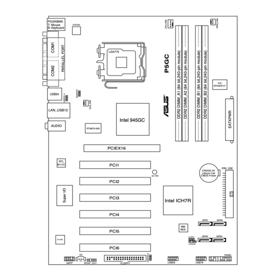
USB34 LAN_USB12 Intel 945GC AUDIO RTM876-660 PCIEX16 PCI1 8111C PRI_IDE CR2032 3V Lithium Cell CMOS Power SB_PWR PCI2 PCI3 Intel ICH7R PCI4 SATA1 SATA2 BIOS PCI5 SATA3 SATA4 CLRTC ALC662 CHASSIS PCI6 PANEL USB56 USB78 AAFP SPDIF_OUT FLOPPY ASUS P5GC... -
Page 26: Layout Contents
2.2.4. Layout.contents Slots Page 1. PCIe x16 2-20 3. PCI 2-20 Jumpers Page 1. Clear RTC RAM (3-pin CLRTC) 2-21 2. Keyboard/mouse power wake-up (3-pin KB/MSPW) 2-22 3. USB Device wake-up (3-pin USBPW1-4, USBPW5-8) 2-22 Rear panel connectors Page PS/2 mouse port (green) 2-23 Parallel port 2-23... - Page 27 ATX power connectors (24-pin EATXPW, 4-pin ATX12V) 2-29 System panel connector (20-8 pin F_PANEL) 2-30 System power LED (2-pin PLED) Hard disk drive activity LED (2-pin IDE_LED) System warning speaker (4-pin SPEAKER) ATX power button/soft-off button (2-pin PWRSW) Reset button (2-pin RESET) ASUS P5GC...
-
Page 28: Central.processing.unit.(Cpu)
ASUS will shoulder the cost of repair only if the damage is shipment/transit-related. • Keep the cap after installing the motherboard. ASUS will process Return Merchandise Authorization (RMA) requests only if the motherboard comes with the cap on the LGA775 socket. - Page 29 (B). Load.plate Position the CPU over the socket, making sure that the gold triangle is on the bottom-left corner of the socket. The socket alignment key should fit Alignment.key into the CPU notch. Gold.triangle.mark ASUS P5GC...
- Page 30 The CPU fits in only one correct orientation. DO NOT force the CPU into the socket to prevent bending the connectors on the socket and damaging the CPU! Close the load plate (A), then push the load lever (B) until it snaps into the retention tab.
-
Page 31: Installing The Cpu Heatsink And Fan
CPU fan cable is closest to the CPU fan connector. Motherboard.hole Narrow.end.. Fastener of.the.groove Make sure to orient each fastener with the narrow end of the groove pointing outward. (The photo shows the groove shaded for emphasis.) ASUS P5GC... - Page 32 Connect the CPU fan cable to the connector on the motherboard labeled CPU_FAN. CPU_FAN CPU FAN PWM CPU FAN IN CPU FAN PWR P5GC.CPU.Fan.Connector Do not forget to connect the CPU fan connector! Hardware monitoring errors can occur if you fail to plug this connector. 2-10 Chapter 2: Hardware information...
-
Page 33: Uninstalling The Cpu Heatsink And Fan
Rotate each fastener counterclockwise. Pull up two fasteners at a time in a diagonal sequence to disengage the heatsink and fan assembly from the motherboard. Carefully remove the heatsink and fan assembly from the motherboard. ASUS P5GC 2-11... - Page 34 Rotate each fastener clockwise to ensure correct orientation when reinstalling. Narrow.end.of.the.groove The narrow end of the groove should point outward after resetting. (The photo shows the groove shaded for emphasis.) Refer to the documentation in the boxed or stand-alone CPU fan package for detailed information on CPU fan installation.
-
Page 35: System.memory
• Always install DIMMs with the same CAS latency. For optimum compatibility, it is recommended that you obtain memory modules from the same vendor. Visit ASUS websie (www.asus.com) for the latest Qualified Vendor Lists. • If you install two1 GB memory modules, the system may only recognize less than 2 GB because the address space is reserved for other critical functions. - Page 36 Qualified Vendors Lists (QVL) DDR2-533 DIMM Size Vendor Mode CL Brand Side(s) Component A B C 256MB Kingston KVR533D2N4/256 Elpida SS E5116AF-5C-E • • • 512MB Kingston KVR533D2N4/512 N/A Infineon SS HYB18T512800AF3733336550 • • • Kingston KVR533D2N4/1G N/A Kingston DS D6408TLRAGL37U •...
- Page 37 SS A3R12E3GEF637BLC5N • • • 512MB PSC AL6E8E63J-6E1 SS A3R12E3JFF717B9A00 • • • AL7E8E63B-6E1K DS A3R12E3GEF637BLC5N • • AL7E8E63J-6E1 DS A3R12E3JFF717B9A01 • • 256MB Nanya NT256T64UH4A1FY-3C Nanya SS NT5TU32M16AG-3C • • • (continued on the next page) ASUS P5GC 2-15...
- Page 38 Supports one pair of modules inserted into either the yellow slots or the black slots as one pair of Dual-channel memory configuration. Supports four modules inserted into both the yellow and black slots as two pairs of Dual-channel memory configuration. Visit the ASUS website for the latest DDR2-667/533 MHz QVL. 2-16 Chapter 2: Hardware information...
-
Page 39: Installing A Dimm
DIMM. Support the DIMM lightly with your fingers when pressing the retaining clips. The DIMM might get damaged when it flips DDR2.DIMM.notch out with extra force. Remove the DIMM from the socket. ASUS P5GC 2-17... -
Page 40: Expansion.slots
Expansion slots In the future, you may need to install expansion cards. The following sub-sections describe the slots and the expansion cards that they support. Make sure to unplug the power cord before adding or removing expansion cards. Failure to do so may cause you physical injury and damage motherboard components. -
Page 41: Interrupt Assignments
— shared Onboard SMBus controller — — — — — — — shared Onboard HD Audio controller — — — shared — — — — Onboard LAN 8111C controller shared — — — — — — — ASUS P5GC 2-19... -
Page 42: Pci Slots
2.5.4. PCI.slots The PCI slots support cards such as a LAN card, SCSI card, USB card, and other cards that comply with PCI specifications. The figure shows a LAN card installed on a PCI slot. 2.5.5. PCI.Express.x16.slot This motherboard supports PCI Express x16 graphic cards that comply with the PCI Express specifications. -
Page 43: Jumpers
You do not need to clear the RTC when the system hangs due to overclocking. For system failure due to overclocking, use the C.P.R. (CPU Parameter Recall) feature. Shut down and reboot the system so the BIOS can automatically reset parameter settings to default values. ASUS P5GC 2-21... - Page 44 Bar). This feature requires an ATX power supply that can supply at least 500 mA on the +5VSB lead, and a corresponding setting in the BIOS. KB/MSPW (Default) P5GC.Keyboard/mouse.Power.Setting The total current consumed must NOT exceed the power supply capability (+5VSB) whether under normal condition or in sleep mode. USB.device.wake-up.(3-pin.USBPW1-4,.USBPW5-8)
-
Page 45: Connectors
6-channel configuration, the function of this port becomes Front Speaker Out. Microphone.port.(pink). This port connects a microphone. Refer to the audio configuration table on next page for the function of the audio ports in 2, 4, or 6-channel configuration. ASUS P5GC 2-23... -
Page 46: Internal Connectors
Pin 5 on the connector is removed to prevent incorrect cable connection when using a FDD cable with a covered Pin 5. FLOPPY NOTE: Orient the red markings on the floppy ribbon cable to PIN 1. P5GC.Floppy.Disk.Drive.Connector 2-24 Chapter 2: Hardware information... - Page 47 IDE cable. • Use the 80-conductor IDE cable for Ultra DMA 100/66/33 IDE devices. IDE.Connector P5GC. Serial.ATA.connectors.(7-pin.SATA1.[red],.SATA2.[red],.SATA3.[black],. SATA4.[black]) These connectors are for the Serial ATA signal cables for Serial ATA hard disk drives. SATA1 SATA2 SATA3 SATA4 P5GC.SATA.Connectors ASUS P5GC 2-25...
- Page 48 This connector is for the 4-pin audio cable that connects to the audio connector at the back of the optical drive. (black) P5GC.Internal.Audio.Connector Digital.Audio.connector.(4-1.pin.SPDIF_OUT) This connector is for the S/PDIF audio module to allow digital sound output. Connect one end of the S/PDIF audio cable to this connector and the other end to the S/PDIF module.
-
Page 49: Front Panel Audio Connector
These USB connectors comply with USB 2.0 specification that supports up to 480 Mbps connection speed. USB56 USB78 P5GC.USB.2.0.Connectors The USB cable is not included in this product. ASUS P5GC 2-27... - Page 50 CHA_FAN +12V Rotation P5GC.CPU.Fan.Connectors Only the CPU_FAN and CHA_FAN connector support the ASUS Q-Fan feature. Chassis.intrusion.connector.(4-1.pin.CHASSIS) This connector is for a chassis-mounted intrusion detection sensor or switch. Connect one end of the chassis intrusion sensor or switch cable to this connector.
- Page 51 +12 Volts +5 Volts +12 Volts +5 Volts +5V Standby +5 Volts Power OK -5 Volts Ground Ground +5 Volts Ground Ground Ground +5 Volts PSON# Ground Ground +3 Volts -12 Volts +3 Volts +3 Volts P5GC.ATX.Power.Connector ASUS P5GC 2-29...
-
Page 52: System Panel Connector
SPEAKER RESET IDE_LED PWRSW Requires an ATX power supply P5GC.System.Panel.Connector •. System.power.LED.(2-pin.PLED) This 2-pin connector is for the system power LED. Connect the chassis power LED cable to this connector. The system power LED lights up when you turn on the system power, and blinks when the system is in sleep mode. - Page 53 This chapter describes the power up sequence, the vocal POST messages, and ways of shutting down the system. Powering up...
-
Page 54: Starting Up For The First Time
Chapter summary Starting up for the first time............3-1 3.2. Powering.off.the.computer............3-2 ASUS P5GC... -
Page 55: Starting Up For The First Time
Two continuous beeps followed by Floppy controller failure two short beeps Two continuous beeps followed by Hardware component failure four short beeps At power on, hold down the <Delete> key to enter the BIOS Setup. Follow the instructions in Chapter 4. ASUS P5GC... -
Page 56: Powering.off.the.computer
Powering off the computer 3.2.1. Using.the.OS.shut.down.function If you are using Windows 2000: ® Click the Start.button then click Shut.Down... Make sure that the Shut.Down option button is selected, then click the OK button to shut down the computer. If you are using Windows ®... -
Page 57: Bios Setup
This chapter tells how to change the system settings through the BIOS Setup menus. Detailed descriptions of the BIOS parameters are also provided. BIOS setup... - Page 58 Chapter summary 4.1. Managing.and.updating.your.BIOS..........4-1 4.2. BIOS.setup.program..............4-11 4.3. Main.menu................... 4-14 4.4. Advanced.menu................4-18 4.5. Power.menu................. 4-28 4.6. Boot.menu................... 4-32 4.7. Tools.menu.................. 4-36 4.8. Exit.menu..................4-37 ASUS P5GC...
-
Page 59: Managing.and.updating.your.bios
The following utilities allow you to manage and update the motherboard Basic Input/Output System (BIOS) setup. ASUS.EZ.Flash.2 (Updates the BIOS using a floppy disk or USB flash disk.) ASUS.AFUDOS (Updates the BIOS in DOS mode using a bootable floppy disk.) ASUS.CrashFree.BIOS.3 (Updates the BIOS using a bootable floppy, USB... -
Page 60: Afudos Utility
Windows 2000 environment ® To create a set of boot disks for Windows 2000: ® a. Insert a formatted, high density 1.44 MB floppy disk into the drive. b. Insert the Windows 2000 CD to the optical drive. ® c. Click Start, then select Run. d. - Page 61 Updating the BIOS file To update the BIOS file using the AFUDOS utility: Visit the ASUS website (www.asus.com) and download the latest BIOS file for the motherboard. Save the BIOS file to a bootable floppy disk. Write the BIOS filename on a piece of paper. You need to type the exact BIOS filename at the DOS prompt.
- Page 62 The utility verifies the file and starts updating the BIOS. A:\>afudos /iP5GC.rom AMI Firmware Update Utility - Version 1.19(ASUS V2.29(07.03.02BA)) Copyright (C) 2003 American Megatrends, Inc. All rights reserved. WARNING!! Do not turn off power during flash BIOS Reading file ..done Reading flash ..
-
Page 63: Asus Crashfree Bios 3 Utility
4.1.3. ASUS.CrashFree.BIOS.3.utility The ASUS CrashFree BIOS 3 is an auto recovery tool that allows you to restore the BIOS file when it fails or gets corrupted during the updating process. You can update a corrupted BIOS file using the motherboard support CD, the USB flash disk, or the floppy disk that contains the updated BIOS file. - Page 64 Visit the ASUS website (www.asus.com) to download the latest BIOS file. • Only the USB flash disk with FAT 32/16 format and single partition can support ASUS CrashFree BIOS 3. The device size should be smaller than 8GB. • DO NOT shut down or reset the system while updating the BIOS! Doing so...
-
Page 65: Asus Ez Flash 2 Utility
4.1.4. ASUS.EZ.Flash.2.utility The ASUS EZ Flash 2 feature allows you to update the BIOS without having to go through the long process of booting from a floppy disk and using a DOS-based utility. The EZ Flash 2 utility is built-in the BIOS chip so it is accessible by pressing <Alt>... -
Page 66: Asus Update Utility
4.1.5. ASUS.Update.utility The ASUS Update is a utility that allows you to manage, save, and update the motherboard BIOS in Windows environment. The ASUS Update utility allows you ® • Save the current BIOS file • Download the latest BIOS file from the Internet •... - Page 67 Updating.the.BIOS.through.the.Internet To update the BIOS through the Internet: desktop by clicking Start. Launch the ASUS Update utility from the Windows ® >.Programs.>.ASUS.>.ASUSUpdate.>.ASUSUpdate. The ASUS Update main window appears. Select Update BIOS from the Select the ASUS FTP site nearest Internet option from the drop-down you to avoid network traffic, or menu, then click Next.
- Page 68 Updating the BIOS through a BIOS file To update the BIOS through a BIOS file: desktop by clicking Start. Launch the ASUS Update utility from the Windows ® >.Programs.>.ASUS.>.ASUSUpdate.>.ASUSUpdate. The ASUS Update main window appears. Select Update BIOS from a file option from the drop-down menu, then click Next.
-
Page 69: Bios.setup.program
The BIOS setup screens shown in this section are for reference purposes only, and may not exactly match what you see on your screen. • Visit the ASUS website (www.asus.com) to download the latest BIOS file for this motherboard. ASUS P5GC... -
Page 70: Bios Menu Screen
4.2.1. BIOS.menu.screen Menu.items Menu.bar Configuration fields General.help BIOS SETUP UTILITY Main Advanced Power Boot Tools Exit Use [ENTER], [TAB] or System Time [17:20:30] [SHIFT-TAB] to select System Time [04:46:19] a field. System Date [Tue 08/28/2007] Legacy Diskette A [1.44M, 3.5 in] Use [+] or [-] to Primary IDE Master : [Not Detected]... -
Page 71: Menu Items
ICH Delayed Transaction [Enabled] Change Option General Help the screen. MPS Revision [1.4] Save and Exit Exit 4.2.9. General.help Pop-up.window At the top right corner of the menu screen Scroll.bar is a brief description of the selected item. ASUS P5GC 4-13... -
Page 72: Main.menu
Main menu When you enter the BIOS Setup program, the Main menu screen appears, giving you an overview of the basic system information. Refer to section “4.2.1 BIOS menu screen” for information on the menu screen items and how to navigate through them. BIOS SETUP UTILITY Main Advanced... -
Page 73: Primary, Third And Fourth Ide Master/Slave
When set to [Disabled], the data transfer from and to the device occurs one sector at a time. Configuration options: [Disabled] [Auto] ASUS P5GC 4-15... -
Page 74: Ide Configuration
PIO.Mode.[Auto] Selects the PIO mode. Configuration options: [Auto] [0] [1] [2] [3] [4] DMA.Mode.[Auto] Selects the DMA mode. Configuration options: [Auto] SMART.Monitoring.[Auto] Sets the Smart Monitoring, Analysis, and Reporting Technology. Configuration options: [Auto] [Disabled] [Enabled] 32Bit.Data.Transfer.[Disabled] Enables or disables 32-bit data transfer. Configuration options: [Disabled] [Enabled] 4.3.5. -
Page 75: System Information
Select Field General Help Save and Exit Exit v02.53 (C)Copyright 1985-2007, American Megatrends, Inc. AMI.BIOS Displays the auto-detected BIOS information. Processor Displays the auto-detected CPU specification. System.Memory Displays the auto-detected total, appropriated (in use), and available system memory. ASUS P5GC 4-17... -
Page 76: Advanced.menu
Advanced menu The Advanced menu items allow you to change the settings for the CPU and other system devices. Take caution when changing the settings of the Advanced menu items. Incorrect field values can cause the system to malfunction. JumperFree Configuration Configure the USB USB Configuration support. - Page 77 1067* FSB 1066 • • • • • • FSB 800 • • • • *.Provided.for.overclocking.purpose.only. Selecting a very high DRAM frequency may cause the system to become unstable! If this happens, revert to the default setting. ASUS P5GC 4-19...
-
Page 78: Usb Configuration
4.4.2 USB Configuration The items in this menu allows you to change the USB-related features. Select an item then press <Enter> to display the configuration options. Enables USB host USB Configuration controllers. Module Version - 2.24.0-F.4 USB Devices Enabled: None USB Function [Enabled] Legacy USB Support... -
Page 79: Cpu Configuration
Allows you to enable or disable C1E suupport. Configuration options: [Disabled] [Enabled] Max CPUID Value Limit [Disabled] Setting this item to [Enabled] allows legacy operating systems to boot even without support for CPUs with extended CPUID functions. Configuration options: [Disabled] [Enabled]. ASUS P5GC 4-21... - Page 80 CPU.TM.function.[Enabled] Allows you to enable or disable CPU TM function. Configuration options: [Enabled] [Disabled]. Execute.Disable.Bit.[Enabled] Allows you to enable or disable the execute disable bit function. Configuration options: [Enabled] [Disabled]. PECI.[Disabled] Allows you to enable or disable PECI interface. Configuration options: [Enabled] [Disabled]. Core.Multi-Processing.[Enabled] Allows you to enable or disable the Intel Core Multi-Processing Technology.
-
Page 81: Chipset
Configuration options: [2 Clocks] [3 Clocks] [4 Clocks] [5 Clocks] [6 Clocks] DRAM # Activate to Precharge [15 Clocks] Configuration options: [4 Clocks] [5 Clocks] ~ [18 Clocks] DRAM Write Recovery Time [4 Clocks] Configuration options: [2 Clocks] [3 Clocks] [4 Clocks] [5 Clocks] [6 Clocks] ASUS P5GC 4-23... - Page 82 Hyper.Path.3.[Auto] Allows you to enable or disable the ASUS Hyper Path 3 feature. Configuration options: [Disabled] [Enabled] [Auto]. DRAM.Throttling.Threshold.[Auto] Enable DRAM Throttling Thermal Throttling will make your system more stable. Configuration options: [Disabled] [Auto]. Booting.Graphic.Adapter.Priority.[PCI.Express/PCI] Allows selection of the graphics controller to use as primary boot device.
-
Page 83: Onboard Devices Configuration
Enabled. Configuration options: [Disabled] [Enabled] Serial.Port1.Address.[3F8/IRQ4] Allows you to select the Serial Port1 base address. Configuration options: [Disabled] [3F8/IRQ4] [3E8/IRQ4] [2E8/IRQ3]. Serial.Port2.Address.[2F8/IRQ3] Allows you to select the Serial Port2 base address. Configuration options: [Disabled] [2F8/IRQ3] [3E8/IRQ4] [2E8/IRQ3]. ASUS P5GC 4-25... -
Page 84: Pci Pnp
Parallel.Port.Address.[378] Allows you to select the Parallel Port base addresses. Configuration options: [Disabled] [378] [278] [3BC]. Parallel.Port.Mode.[ECP] Allows you to select the Parallel Port mode. Configuration options: [Normal] [Bi-directional] [EPP] [ECP]. ECP Mode DMA Channel [DMA3] Appears only when the Parallel Port Mode is set to [ECP]. This item allows you to set the Parallel Port ECP DMA. - Page 85 Configuration options: [Disabled] [Enabled]. IRQ-xx.assigned.to.[PCI.Device] When set to [PCI Device], the specific IRQ is free for use of PCI/PnP devices. When set to [Reserved], the IRQ is reserved for legacy ISA devices. Configuration options: [PCI Device] [Reserved] ASUS P5GC 4-27...
-
Page 86: Power.menu
Power menu The Power menu items allow you to change the settings for the ACPI and Advanced Power Management (APM) features. Select an item then press <Enter> to display the configuration options. Suspend Mode [Auto] Select the ACPI state ACPI 2.0 Support [Disabled] used for System ACPI APIC Support... -
Page 87: Apm Configuration
Configuration options: [Everyday] [1] [2] [3]... ~ [31] RTC Alarm Hour [xx] To set the alarm hour, highlight this item and press the <+> or <-> key to make the selection. Configuration options: [00] [1]... ~ [23] ASUS P5GC 4-29... - Page 88 RTC Alarm Minute [xx] To set the alarm minute, highlight this item and press the <+> or <-> key to make the selection. Configuration options: [00] [1]... ~ [59] RTC Alarm Second [xx] To set the alarm second, highlight this item and press the <+> or <->...
-
Page 89: Hardware Monitor
(RPM). If the fan is not connected to the motherboard, the field shows N/A. CPU.Q-Fan.Control.[Disabled] Allows you to enable or disable the ASUS Q-Fan feature that smartly adjusts the fan speeds for more efficient system operation. Configuration options: [Disabled] [Enabled] The CPU Fan Profile Mode item appears when you enable the CPU Q-Fan Control feature. -
Page 90: Boot.menu
Boot menu The Boot menu items allow you to change the system boot options. Select an item then press <Enter> to display the sub-menu. BIOS SETUP UTILITY Main Advanced Power Boot Boot Tools Exit Specifies the Boot Boot Settings Device Priority Boot Device Priority Sequence. -
Page 91: Boot Settings Configuration
Full.Screen.Logo.[Enabled] Allows you to enable or disable the full screen logo display feature. Configuration options: [Disabled] [Enabled] Set this item to [Enabled] to use the ASUS MyLogo2™ feature. Add.On.ROM.Display.Mode.[Force.BIOS] Sets the display mode for option ROM. Configuration options: [Force BIOS] [Keep Current] Bootup.Num-Lock.[On]... -
Page 92: Security
Interrupt.19.Capture.[Disabled] When set to [Enabled], this function allows the option ROMs to trap Interrupt 19. Configuration options: [Disabled] [Enabled] 4.6.3. Security The Security menu items allow you to change the system security settings. Select an item then press <Enter> to display the configuration options. BIOS SETUP UTILITY Boot <Enter>... - Page 93 <Enter>. Confirm the password when prompted. The message “Password Installed” appears after you set your password successfully. To change the user password, follow the same steps as in setting a user password. ASUS P5GC 4-35...
-
Page 94: Tools.menu
(C)Copyright 1985-2007, American Megatrends, Inc. ASUS.EZ.Flash.2 Allows you to run ASUS EZ Flash 2. When you press <Enter>, a confirmation message appears. Use the left/right arrow key to select between [Yes] or [No], then press <Enter> to confirm your choice. Please see section 4.1.4 for details. -
Page 95: Exit.menu
Time, and Password, the BIOS asks for a confirmation before exiting. Discard.Changes Allows you to discard the selections you made and restore the previously saved values. After selecting this option, a confirmation appears. Select <OK> to discard any changes and load the previously saved values. ASUS P5GC 4-37... - Page 96 Load.Setup.Defaults. Allows you to load the default values for each of the parameters on the Setup menus. When you select this option or if you press <F5>, a confirmation window appears. Select <OK> to load the default values. Select Exit & Save Changes or make other changes before saving the values to the non-volatile RAM.- 4-38 Chapter 4: BIOS setup...
-
Page 97: Software Support
This chapter describes the contents of the support CD that comes with the motherboard package. Software support... - Page 98 Chapter summary 5.1. Installing.an.operating.system............ 5-1 5.2. Support.CD.information............... 5-1 ASUS P5GC...
-
Page 99: Installing.an.operating.system
The support CD that came with the motherboard package contains the drivers, and utilities that you can install to avail all motherboard features. The contents of the support CD are subject to change at any time without notice. Visit the ASUS website (www.asus.com) for updates. 5.2.1. Running.the.support.CD Place the support CD to the optical drive. -
Page 100: Drivers Menu
The drivers menu shows the available device drivers if the system detects installed devices. Install the necessary drivers to activate the devices. ASUS.InstALL.-.Drivers.Installation.Wizard Installs the ASUS InstALL - Drivers Installation Wizard. Intel.Chipset.Inf.Update.Program Installs the Intel Chipset Inf Update Program. Realtek.Audio.Driver Install the Realtek Audio Driver. -
Page 101: Utilities Menu
ASUS.Update. Allows you to download the latest version of the BIOS from the ASUS website. Before using the ASUS Update, make sure that you have an Internet connection so you can connect to the ASUS website. - Page 102 Install the following utilities from the ASUS Superb Software Library CD if needed.. ADOBE Acrobat Reader V7.0 Installs the Adobe Acrobat Reader that allows you to open, view, and ® ® print documents in Portable Document Format (PDF). Microsoft.DirectX.9.0c Installs the Microsoft DirectX 9.0c driver.
-
Page 103: Make Disk Menu
The Make Disk menu contains items to create Intel ICH7R RAID/AHCI driver disk. ® Intel.ICH7R.32.bit.RAID/AHCI.Driver. Allows you to create an Intel ICH7R 32 bit RAID/AHCI driver. Intel.ICH7R.64.bit.RAID/AHCI.Driver. Allows you to create an Intel ICH7R 64 bit RAID/AHCI driver. ASUS P5GC... -
Page 104: Manual Menu
Acrobat Reader application from the.Utilities tab before opening a user manual file. 5.2.6. ASUS.Contact.information Click the Contact tab to display the ASUS contact information. You can also find this information on the inside front cover of this user guide. Chapter 5: Software support... -
Page 105: Other Information
The icons on the top right corner of the screen give additional information on the motherboard and the contents of the support CD. Click an icon to display the specified information. Motherboard.Info Displays the general specifications of the motherboard. Browse.this.CD Displays the support CD contents in graphical format. ASUS P5GC... - Page 106 Technical.support.Form Displays the ASUS Technical Support Request Form that you have to fill out when requesting technical support. Filelist Displays the contents of the support CD and a brief description of each in text format. Chapter 5: Software support...
-
Page 107: Appendix:.cpu.features
The Appendix describes the CPU features that the motherboard supports. CPU features... -
Page 108: Chapter Summary
Chapter summary A.1. Enhanced.Intel.SpeedStep .Technology.(EIST)......A-1 ® A.2. Intel .Hyper-Threading.Technology..........A-2 ® ASUS P5GC... -
Page 109: Enhanced Intel Speedstep Technology (Eist)
® Technology (EIST) • The motherboard comes with a BIOS file that supports EIST. You can download the latest BIOS file from the ASUS website (www.asus.com/ support/download/) if you need to update the BIOS. See Chapter 4 for details. •... -
Page 110: Intel ® Hyper-Threading Technology
On the Power schemes section, click , then select any option except Home/ Office Desktop or Always On. Click Apply, then click OK. 10. Close the Display Properties window. After you adjust the power scheme, the CPU internal frequency slightly decreases when the CPU loading is low.