Table of Contents
Advertisement
Advertisement
Table of Contents

Related Manuals for Asus P4S8X-MX


Summary of Contents for Asus P4S8X-MX
- Page 1 P4S8X-MX...
- Page 2 Product warranty or service will not be extended if: (1) the product is repaired, modified or altered, unless such repair, modification of alteration is authorized in writing by ASUS; or (2) the serial number of the product is defaced or missing.
-
Page 3: Table Of Contents
Contents Notices ....................vi Safety information ................vii P4S8X-MX specifications summary ........... viii Chapter 1: Product introduction Chapter 1: Product introduction Chapter 1: Product introduction Chapter 1: Product introduction Chapter 1: Product introduction Welcome! ................1-2 Package contents ..............1-2 Special features .............. - Page 4 Creating a bootable floppy disk ......2-2 2.1.2 ASUS EZ Flash utility ..........2-3 2.1.3 AFUDOS utility ............2-4 2.1.4 ASUS CrashFree BIOS 2 utility ........ 2-6 2.1.5 ASUS Update utility ..........2-8 BIOS setup program ............2-11 2.2.1 BIOS menu screen ..........2-12 2.2.2...
- Page 5 3.2.1 Running the support CD ......... 3-2 3.2.2 Drivers menu ............3-3 3.2.3 Utilities menu ............3-4 3.2.4 ASUS Contact information ........3-6 3.2.5 Other information ........... 3-6 RAID configurations .............. 3-8 3.3.1 Installing hard disks ..........3-8 3.3.2 SIS RAID configurations .......... 3-9 Creating a RAID driver disk ..........
-
Page 6: Notices
Notices Federal Communications Commission Statement Federal Communications Commission Statement Federal Communications Commission Statement Federal Communications Commission Statement Federal Communications Commission Statement This device complies with Part 15 of the FCC Rules. Operation is subject to the following two conditions: • This device may not cause harmful interference, and •... -
Page 7: Safety Information
Safety information Electrical safety Electrical safety Electrical safety Electrical safety Electrical safety • To prevent electrical shock hazard, disconnect the power cable from the electrical outlet before relocating the system. • When adding or removing devices to or from the system, ensure that the power cables for the devices are unplugged before the signal cables are connected. -
Page 8: P4S8X-Mx Specifications Summary
O v e r c l o c k i n g O v e r c l o c k i n g to 200 MHz at 1 MHz increment AGP/PCI Asynchronous Mode with FSB ASUS C.P.R. (CPU Parameter Recall) U S B U S B U S B Supports up to 8 USB 2.0 ports... - Page 9 P4S8X-MX specifications summary B I O S f e a t u r e s B I O S f e a t u r e s B I O S f e a t u r e s B I O S f e a t u r e s B I O S f e a t u r e s 4 Mb Flash ROM, AMI BIOS, Green, PnP, DMI2.0,...
- Page 10 x x x x x...
- Page 11 This chapter describes the motherboard features and the new technologies it supports. Product introduction...
-
Page 12: Welcome
P 4 S 8 X - M X m o t h e r b o a r d ! The motherboard delivers a host of new features and latest technologies, making it another standout in the long line of ASUS quality motherboards! Before you start installing the motherboard, and hardware devices on it, check the items in your package with the list below. - Page 13 LPC and AC’97 interfaces, and complies with the Advanced Power Management (APM) 1.2 specification. The SiS964 interconnects with the Northbridge at up to 1GB/s using the SiS proprietary MuTIOL ® interface. Real256E integrated graphics Real256E integrated graphics Real256E integrated graphics Real256E integrated graphics Real256E integrated graphics Embedded in the Northbridge is the SiS Real256E integrated graphics with...
- Page 14 ASUS EZ Flash BIOS ASUS EZ Flash BIOS With the ASUS EZ Flash, you can easily update the system BIOS even before loading the operating system. No need to use a DOS-based utility or boot from a floppy disk. See page 2-3 for details.
-
Page 15: Before You Proceed
LED. SB_PWR Standby Powered Power P4S8X-MX Onboard LED A S U S P 4 S 8 X - M X A S U S P 4 S 8 X - M X 1 - 5 1 - 5 A S U S P 4 S 8 X - M X... -
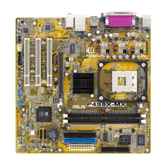
Page 16: Motherboard Overview
Motherboard overview 1.5.1 1.5.1 Motherboard layout Motherboard layout 1.5.1 1.5.1 1.5.1 Motherboard layout Motherboard layout Motherboard layout 24.5cm (9.6in) KBPWR PS/2KBMS Super T: Mouse B: Keyboard CPU_FAN1 COM1 Socket 478 USB12 ATX12V USB34 661GX RJ-45 North Bridge USBPW34 USBPW12 Top:Line In Center:Line Out Below:Mic In CR2032 3V... -
Page 17: Placement Direction
1.5.2 1.5.2 1.5.2 Placement direction Placement direction Placement direction 1.5.2 1.5.2 Placement direction Placement direction When installing the motherboard, make sure that you place it into the chassis in the correct orientation. The edge with external ports goes to the rear part of the chassis as indicated in the image below. -
Page 18: Central Processing Unit (Cpu)
Follow these steps to install a CPU. Locate the 478-pin ZIF socket on the motherboard. Gold Arrow P4S8X-MX CPU Socket 478 1 - 8 1 - 8 C h a p t e r 1 : P r o d u c t i n t r o d u c t i o n... - Page 19 Unlock the socket by pressing the lever sideways, then lift it up to a 90°-100° angle. 9 0 ° - 1 0 0 ° 9 0 ° - 1 0 0 ° 9 0 ° - 1 0 0 ° 9 0 °...
- Page 20 When the CPU is in place, push down the socket lever to secure the CPU. The lever clicks on the side tab to indicate that it is locked. After installation, make sure to plug the 4-pin ATX power cable to the motherboard.
-
Page 21: Installing The Heatsink And Fan
1.6.3 1.6.3 1.6.3 Installing the heatsink and fan Installing the heatsink and fan Installing the heatsink and fan 1.6.3 1.6.3 Installing the heatsink and fan Installing the heatsink and fan The Intel ® Pentium ® 4 Processor requires a specially designed heatsink and fan assembly to ensure optimum thermal condition and performance. - Page 22 Position the fan with the retention mechanism on top of the heatsink. Align and snap the four hooks of the retention mechanism to the holes on each corner of the module base. Make sure that the fan and retention mechanism assembly perfectly fits the heatsink and module base;...
- Page 23 When the fan and heatsink assembly is in place, connect the CPU fan cable to the connector on the motherboard labeled CPU_FAN1. CPU_FAN1 P4S8X-MX CPU fan connector Do not forget to connect the CPU fan connector! Hardware monitoring errors can occur if you fail to plug this connector.
-
Page 24: System Memory
• Installing DDR DIMMs other than the recommended configurations may cause memory sizing error or system boot failure. • Visit the ASUS website (www.asus.com) for the latest DDR Qualified Vendors List (QVL). 1 - 1 4 1 - 1 4... - Page 25 DDR400* Qualified Vendors List DDR400* Qualified Vendors List DDR400* Qualified Vendors List DDR400* Qualified Vendors List DDR400* Qualified Vendors List D I M M s u p p o r t D I M M s u p p o r t D I M M s u p p o r t D I M M s u p p o r t D I M M s u p p o r t...
-
Page 26: Installing A Dimm
1.7.3 1.7.3 1.7.3 Installing a DIMM Installing a DIMM Installing a DIMM 1.7.3 1.7.3 Installing a DIMM Installing a DIMM Make sure to unplug the power supply before adding or removing DIMMs or other system components. Failure to do so may cause severe damage to both the motherboard and the components. -
Page 27: Expansion Slots
Expansion slots In the future, you may need to install expansion cards. The following sub-sections describe the slots and the expansion cards that they support. Make sure to unplug the power cord before adding or removing expansion cards. Failure to do so may cause you physical injury and damage motherboard components. - Page 28 Standard interrupt assignments Standard interrupt assignments Standard interrupt assignments Standard interrupt assignments Standard interrupt assignments I R Q I R Q I R Q I R Q I R Q P r i o r i t y P r i o r i t y P r i o r i t y P r i o r i t y P r i o r i t y...
-
Page 29: Pci Slots
This motherboard does not support 3.3V AGP cards. Install only +1.5V AGP cards. Keyed for 1.5v P4S8X-MX Accelerated Graphics Port (AGP) A S U S P 4 S 8 X - M X A S U S P 4 S 8 X - M X... -
Page 30: Jumpers
Clear CMOS Normal (Default) P4S8X-MX Clear RTC RAM You do not need to clear the RTC when the system hangs due to overclocking. For system failure due to overclocking, use the C.P.R. (CPU Parameter Recall) feature. Shut down and reboot the system so the BIOS can automatically reset parameter settings to default values. - Page 31 +5VSB (Default) USBPW56 USBPW78 +5VSB P4S8X-MX USB device wake up (Default) • The USB device wake-up feature requires a power supply that can provide 500mA on the +5VSB lead for each USB port; otherwise, the system would not power up.
- Page 32 +5VSB (Default) P4S8X-MX Keyboard power setting C h a p t e r 1 : P r o d u c t i n t r o d u c t i o n C h a p t e r 1 : P r o d u c t i n t r o d u c t i o n...
-
Page 33: 1.10 Connectors
1.10 Connectors 1.10.1 1.10.1 1.10.1 Rear panel connectors 1.10.1 1.10.1 Rear panel connectors Rear panel connectors Rear panel connectors Rear panel connectors 1 . 1 . P S / 2 m o u s e p o r t ( g r e e n ) . P S / 2 m o u s e p o r t ( g r e e n ) . - Page 34 7 . 7 . U S B 2 . 0 p o r t s 3 a n d 4 . U S B 2 . 0 p o r t s 3 a n d 4 . These two 4-pin Universal Serial Bus U S B 2 .
-
Page 35: Internal Connectors
NOTE: Orient the red markings on the floppy ribbon cable to PIN 1. PIN 1 P4S8X-MX Floppy disk drive connector A S U S P 4 S 8 X - M X A S U S P 4 S 8 X - M X... - Page 36 PIN 1. PIN 1 P4S8X-MX IDE connectors C h a p t e r 1 : P r o d u c t i n t r o d u c t i o n C h a p t e r 1 : P r o d u c t i n t r o d u c t i o n...
- Page 37 MB/s data transfer rate, faster than the standard parallel ATA with 133 MB/s (Ultra DMA/133) SATA2 P4S8X-MX SATA connectors SATA1 If you install SATA hard disk drives, you can create a RAID 0, RAID 1, or JBOD configuration with the SIS964 RAID controller. Refer to page 2-16 for the BIOS setting and page 3-18 for creating a RAID driver disk.
- Page 38 CPU_FAN1 P4S8X-MX CPU fan connector 5 . 5 . G A M E / M I D I c o n n e c t o r ( 1 6 - 1 p i n G A M E 1 )
- Page 39 USB 2.0 specification that supports up to 480 Mbps connection speed. USB56 USB78 P4S8X-MX USB 2.0 connectors 1 3 9 4 c a b l e 1 3 9 4 c a b l e Never connect a 1 3 9 4 c a b l e 1 3 9 4 c a b l e 1 3 9 4 c a b l e to the USB connectors.
- Page 40 I/O module cable to this connector. FP_AUDIO1 P4S8X-MX Front panel audio connector C h a p t e r 1 : P r o d u c t i n t r o d u c t i o n...
- Page 41 Connect one end of the S/PDIF audio cable this connector and the other end to the S/PDIF module. SPDIF P4S8X-MX Digital Audio Connector The S/PDIF module is purchased separately. A S U S P 4 S 8 X - M X...
-
Page 42: System Panel Connector
RESET IDE_LED PWRSW Requires an ATX power supply. P4S8X-MX System panel connector The sytem panel connector is color-coded for easy connection. Refer to the connector description below for details. • S y s t e m p o w e r L E D ( G r e e n 3 - p i n P L E D ) - Page 43 This chapter tells how to change the system settings through the BIOS Setup menus. Detailed descriptions of the BIOS parameters are also provided. BIOS setup...
-
Page 44: Managing And Updating Your Bios
Refer to the corresponding sections for details on these utilities. Save a copy of the original motherboard BIOS file to a bootable floppy disk in case you need to restore the BIOS in the future. Copy the original motherboard BIOS using the ASUS Update or AFUDOS utilities. 2.1.1 2.1.1... -
Page 45: Asus Ez Flash Utility
ASUS EZ Flash utility ASUS EZ Flash utility The ASUS EZ Flash feature allows you to update the BIOS without having to go through the long process of booting from a floppy disk and using a DOS-based utility. The EZ Flash utility is built-in the BIOS chip so it is accessible by pressing <Alt>... -
Page 46: Afudos Utility
2.1.3 2.1.3 2.1.3 AFUDOS utility AFUDOS utility AFUDOS utility 2.1.3 2.1.3 AFUDOS utility AFUDOS utility The AFUDOS utility allows you to update the BIOS file in DOS environment using a bootable floppy disk with the updated BIOS file. This utility also allows you to copy the current BIOS file that you can use as backup when the BIOS fails or gets corrupted during the updating process. - Page 47 Updating the BIOS file To update the BIOS file using the AFUDOS utility: Visit the ASUS website (www.asus.com) and download the latest BIOS file for the motherboard. Save the BIOS file to a bootable floppy disk. Write the BIOS filename on a piece of paper. You need to type the exact BIOS filename at the DOS prompt.
-
Page 48: Asus Crashfree Bios 2 Utility
ASUS CrashFree BIOS 2 utility ASUS CrashFree BIOS 2 utility The ASUS CrashFree BIOS 2 is an auto recovery tool that allows you to restore the BIOS file when it fails or gets corrupted during the updating process. You can update a corrupted BIOS file using the motherboard support CD or the floppy disk that contains the updated BIOS file. - Page 49 Restart the system after the utility completes the updating process. The recovered BIOS may not be the latest BIOS version for this motherboard. Visit the ASUS website (www.asus.com) to download the latest BIOS file. A S U S P 4 S 8 X - M X...
-
Page 50: Asus Update Utility
ASUS Update utility 2.1.5 2.1.5 ASUS Update utility ASUS Update utility The ASUS Update is a utility that allows you to manage, save, and update the motherboard BIOS in Windows ® environment. The ASUS Update utility allows you to: • Save the current BIOS file •... - Page 51 Updating the BIOS through the Internet Updating the BIOS through the Internet Updating the BIOS through the Internet To update the BIOS through the Internet: Launch the ASUS Update utility from the Windows ® desktop by clicking S t a r t S t a r t >...
- Page 52 A S U S U p d a t e A S U S U p d a t e A S U S U p d a t e. The ASUS Update main window appears. A S U S U p d a t e...
-
Page 53: Bios Setup Program
• Visit the ASUS website (www.asus.com) to download the latest BIOS file for this motherboard and . A S U S P 4 S 8 X - M X... -
Page 54: Bios Menu Screen
Legacy Diskette A [1.44M, 3.5 in] Use [+] or [-] to Primary IDE Master [ST320410A] configure the System Primary IDE Slave [ASUS CD-S520/A] Time. Secondary IDE Master [Not Detected] Secondary IDE Slave [Not Detected] OnChip SATA Controller [RAID Mode]... -
Page 55: Menu Items
[1.44M, 3.5 in] select a field. bar displays the specific items for Primary IDE Master :[ST320410A] Use [+] or [-] to Primary IDE Slave :[ASUS CD-S520/A] configure the Secondary IDE Master :[Not Detected] that menu. For example, selecting System Time. -
Page 56: Main Menu
Legacy Diskette A [1.44M, 3.5 in] Use [+] or [-] to Primary IDE Master [ST320410A] configure the System Primary IDE Slave [ASUS CD-S520/A] Time. Secondary IDE Master [Not Detected] Secondary IDE Slave [Not Detected] OnChip SATA Controller [RAID Mode] System Information 2.3.1... -
Page 57: Primary And Secondary Ide Master/Slave
2.3.4 2.3.4 2.3.4 Primary and Secondary IDE Master/Slave Primary and Secondary IDE Master/Slave Primary and Secondary IDE Master/Slave 2.3.4 2.3.4 Primary and Secondary IDE Master/Slave Primary and Secondary IDE Master/Slave While entering Setup, the BIOS automatically detects the presence of IDE devices. -
Page 58: Onchip Sata Controller
PIO Mode [Auto] PIO Mode [Auto] PIO Mode [Auto] PIO Mode [Auto] PIO Mode [Auto] Selects the PIO mode. Configuration options: [Auto] [0] [1] [2] [3] [4] DMA Mode [Auto] DMA Mode [Auto] DMA Mode [Auto] DMA Mode [Auto] DMA Mode [Auto] Selects the DMA mode. -
Page 59: Advanced Menu
AMI BIOS AMI BIOS AMI BIOS AMI BIOS AMI BIOS Displays the auto-detected BIOS information. Processor Processor Processor Processor Processor Displays the auto-detected CPU specification. System Memory System Memory System Memory System Memory System Memory Displays the auto-detected system memory. Advanced menu The Advanced menu items allow you to change the settings for the CPU and other system devices. -
Page 60: Jumperfree Configuration
2.4.1 2.4.1 2.4.1 JumperFree Configuration JumperFree Configuration JumperFree Configuration 2.4.1 2.4.1 JumperFree Configuration JumperFree Configuration Configure System Frequency Select the target CPU frequency, and the AI Overclock Tuner [Manual] relevant parameters CPU Frequency [133] will be auto-adjusted. AGP/PCI Frequency [Auto] Frequencies higher Spread Spectrum [Enabled]... - Page 61 AGP/PCI Frequency [Auto] AGP/PCI Frequency [Auto] AGP/PCI Frequency [Auto] AGP/PCI Frequency [Auto] AGP/PCI Frequency [Auto] Allows you to set the AGP/PCI operating frequency. Configuration options: [Auto][ 66.6/33.3] [75.0/37.5] [85.7/42.8] Spread Spectrum [Enabled] Spread Spectrum [Enabled] Spread Spectrum [Enabled] Spread Spectrum [Enabled] Spread Spectrum [Enabled] Enables or disables the clock generator spread spectrum.
-
Page 62: Cpu Configuration
2.4.2 2.4.2 2.4.2 CPU Configuration CPU Configuration CPU Configuration 2.4.2 2.4.2 CPU Configuration CPU Configuration The items in this menu show the CPU-related information that the BIOS automatically detects. Configure Advanced CPU settings Sets the ratio between CPU Core Clock and the Manufacturer: Intel FSB Frequency. -
Page 63: Chipset
2.4.3 2.4.3 2.4.3 Chipset Chipset Chipset 2.4.3 2.4.3 Chipset Chipset The Chipset menu items allow you to change the advanced chipset settings. Select an item then press Enter to display the sub-menu. NorthBridge SIS661GX Configuration SouthBridge SIS964 Configuration NorthBridge SiS661GX Configuration NorthBridge SiS661GX Configuration NorthBridge SiS661GX Configuration NorthBridge SiS661GX Configuration... - Page 64 DRAM RAS# Precharge [Auto] Controls the idle clocks after issuing a precharge command to the DDR SDRAM. Configuration options: [Auto] [3T] [2T] [4T] [5T] Graphics Win Size [64MB] Allows you to select the size of mapped memory for AGP graphic data.
-
Page 65: Onboard Devices Configuration
2.4.4 2.4.4 2.4.4 Onboard Devices Configuration Onboard Devices Configuration Onboard Devices Configuration 2.4.4 2.4.4 Onboard Devices Configuration Onboard Devices Configuration Allows BIOS to Configure Onboard Device select Serial Port1 Base addresses. Serial Port1 Address [3F8/IRQ4] Parallel Port Address [378] Parallel Port Mode [ECP] ECP Mode DMA Channel [DMA3]... -
Page 66: Pci Pnp
2.4.5 2.4.5 2.4.5 PCI PnP PCI PnP PCI PnP 2.4.5 2.4.5 PCI PnP PCI PnP The PCI PnP menu items allow you to change the advanced settings for PCI/PnP devices. The menu includes setting IRQ and DMA channel resources for either PCI/PnP or legacy ISA devices, and setting the memory size block for legacy ISA devices. -
Page 67: Usb Configuration
2.4.6 2.4.6 2.4.6 USB Configuration USB Configuration USB Configuration 2.4.6 2.4.6 USB Configuration USB Configuration The items in this menu allows you to change the USB-related features. Select an item then press <Enter> to display the configuration options. OnBoard SiS USB1.1 Device [Enabled] OnBoard SiS USB2.0 Device [Enabled]... -
Page 68: Power Menu
Power menu The Power menu items allow you to change the settings for the Advanced Power Management (APM). Select an item then press <Enter> to display the configuration options. Select the ACPI state Suspend Mode [Auto] used for System ACPI 2.0 Support [No] Suspend. -
Page 69: Apm Configuration
2.5.4 2.5.4 2.5.4 APM Configuration APM Configuration APM Configuration 2.5.4 2.5.4 APM Configuration APM Configuration APM Configuration <Enter> to select whether or not to Power Button Mode [On/Off] restart the system after AC power loss. Restore on AC Power Loss [Always OFF] Power On By PS2 Keyboard [Disabled]... - Page 70 Power On By PCI Devices [Disabled] Power On By PCI Devices [Disabled] Power On By PCI Devices [Disabled] Power On By PCI Devices [Disabled] Power On By PCI Devices [Disabled] When set to [Enabled], this parameter allows you to turn on the system through a PCI LAN or modem card.
-
Page 71: Hardware Monitor
2.5.5 2.5.5 2.5.5 Hardware Monitor Hardware Monitor Hardware Monitor 2.5.5 2.5.5 Hardware Monitor Hardware Monitor Hardware Monitor CPU Temperature CPU Temperature [65.5ºC/148ºF] MB Temperature [36ºC/96.5ºF] CPU Fan Speed [3260RPM] Chassis Fan Speed [N/A] VCORE Voltage [ 1.504V] 3.3V Voltage [ 3.360V] 5V Voltage [ 5.160V] 12V Voltage... -
Page 72: Boot Menu
2nd Boot Device [PM-ST330620A] 3rd Boot Device [PS-ASUS CD-S360] 1st ~ xxth Boot Device [1st Floppy Drive] 1st ~ xxth Boot Device [1st Floppy Drive] 1st ~ xxth Boot Device [1st Floppy Drive] 1st ~ xxth Boot Device [1st Floppy Drive]... -
Page 73: Removable Drives
This allows you to enable or disable the full screen logo display feature. Configuration options: [Disabled] [Enabled] Set this item to [Enabled] to use the ASUS MyLogo2™ feature. A S U S P 4 S 8 X - M X... - Page 74 Add On ROM Display Mode [Force BIOS] Add On ROM Display Mode [Force BIOS] Add On ROM Display Mode [Force BIOS] Add On ROM Display Mode [Force BIOS] Add On ROM Display Mode [Force BIOS] Sets the display mode for option ROM. Configuration options: [Force BIOS] [Keep Current] Bootup Num-Lock [On] Bootup Num-Lock [On]...
-
Page 75: Security
2.6.4 2.6.4 2.6.4 Security Security Security 2.6.4 2.6.4 Security Security The Security menu items allow you to change the system security settings. Select an item then press <Enter> to display the configuration options. Security Settings <Enter> to change password. Supervisor Password : Not Installed <Enter>... - Page 76 After you have set a supervisor password, the other items appear to allow you to change other security settings. Security Settings Supervisor Password : Not Installed User Password : Not Installed Change Supervisor Password User Access Level [Full Access] Change User Password Clear User Password Password Check [Setup]...
-
Page 77: Exit Menu
The message “Password Installed” appears after you set your password successfully. To change the user password, follow the same steps as in setting a user password. Clear User Password Clear User Password Clear User Password Clear User Password Clear User Password Select this item to clear the user password. - Page 78 Exit & Save Changes Exit & Save Changes Exit & Save Changes Exit & Save Changes Exit & Save Changes Once you are finished making your selections, choose this option from the Exit menu to ensure the values you selected are saved to the CMOS RAM. An onboard backup battery sustains the CMOS RAM so it stays on even when the PC is turned off.
- Page 79 This chapter describes the contents of the support CD that comes with the motherboard package. Software support...
-
Page 80: Installing An Operating System
The contents of the support CD are subject to change at any time without notice. Visit the ASUS website(www.asus.com) for updates. 3.2.1 3.2.1 Running the support CD Running the support CD 3.2.1... -
Page 81: Drivers Menu
3.2.2 3.2.2 3.2.2 Drivers menu Drivers menu Drivers menu 3.2.2 3.2.2 Drivers menu Drivers menu The drivers menu shows the available device drivers if the system detects installed devices. Install the necessary drivers to activate the devices. SiS AGP Driver SiS AGP Driver SiS AGP Driver SiS AGP Driver... -
Page 82: Utilities Menu
ASUS Update ASUS Update ASUS Update ASUS Update The ASUS Update utility allows you to update the motherboard BIOS in a Windows ® environment. This utility requires an Internet connection either through a network or an Internet Service Provider (ISP). - Page 83 ASUS Screen Saver ASUS Screen Saver ASUS Screen Saver Installs the ASUS screen saver. The screen display and utilities option may not be the same for different operating system versions. A S U S P 4 S 8 X - M X...
-
Page 84: Asus Contact Information
C o n t a c t C o n t a c t C o n t a c t tab to display the ASUS contact information. You can also find this information on the inside front cover of this user guide. - Page 85 Displays the support CD contents in graphical format. Technical support Form Technical support Form Technical support Form Technical support Form Technical support Form Displays the ASUS Technical Support Request Form that you have to fill out when requesting technical support. Filelist Filelist Filelist Filelist...
-
Page 86: Raid Configurations
RAID configurations The SIS 964 southbridge comes with a RAID controller that allows you to configure Serial ATA hard disk drives as RAID sets. The motherboard supports the following RAID configurations. R A I D 0 R A I D 0 R A I D 0 (Data striping) optimizes two identical hard disk drives to read and R A I D 0 R A I D 0... -
Page 87: Sis Raid Configurations
3.3.2 3.3.2 3.3.2 SIS RAID configurations SIS RAID configurations SIS RAID configurations 3.3.2 3.3.2 SIS RAID configurations SIS RAID configurations The motherboard includes a high performance Serial ATA RAID controller integrated in the SIS 964 Southbridge chipset. It supports RAID 0 and RAID 1 with two independent Serial ATA channels. - Page 88 Creating JBOD Creating JBOD Creating JBOD Creating JBOD Creating JBOD From the RAID Setup, press < 1 > < 1 > < 1 > < 1 > < 1 > then < E n t e r > < E n t e r > <...
- Page 89 The current RAID set is displayed on the upper side of the screen. Press < Q > < Q > < Q > < Q > to exit the RAID setup. < Q > Press < Y > < Y > <...
- Page 90 Creating RAID 0 for performance Creating RAID 0 for performance Creating RAID 0 for performance Creating RAID 0 for performance Creating RAID 0 for performance From the RAID Setup, press < 2 > < 2 > < 2 > < 2 > <...
- Page 91 Use the u p / d o w n u p / d o w n u p / d o w n u p / d o w n arrow keys to move the selection bar, then press u p / d o w n <...
- Page 92 10. The current RAID setup is displayed on the upper side of the screen. Press < Q > < Q > < Q > < Q > < Q > to exit the RAID setup menu. 11. Press < Y > <...
- Page 93 Creating RAID 1 for capacity Creating RAID 1 for capacity Creating RAID 1 for capacity Creating RAID 1 for capacity Creating RAID 1 for capacity From the RAID Setup, press < 3 > < 3 > < 3 > < 3 > then < E n t e r > <...
- Page 94 Press < N > < N > < N > < N > then < E n t e r > < E n t e r > < E n t e r > < E n t e r > to create a mirrored set. Press < Y > <...
- Page 95 Press < Q > < Q > < Q > < Q > to exit the RAID setup. < Q > < Y > < Y > < E n t e r > < E n t e r > Press <...
-
Page 96: Creating A Raid Driver Disk
Creating a RAID driver disk A floppy disk with the RAID driver is required when installing Windows ® 2000/XP operating system on a hard disk drive that is included in a RAID set. Use the support CD that came with the motherboard package to create a RAID driver disk.