Table of Contents
Advertisement
Advertisement
Table of Contents

Related Manuals for Asus A7S333


Summary of Contents for Asus A7S333
- Page 1 ® A7S333 User Guide...
- Page 2 Product warranty or service will not be extended if: (1) the product is repaired, modified or altered, unless such repair, modification of alteration is authorized in writing by ASUS; or (2) the serial number of the product is defaced or missing.
-
Page 3: Conventions Used In This Guide
About this guide This user manual contains complete information for installing the ASUS A7S333 motherboard. How this guide is organized • Chapter 1: Product introduction. A summary of product features and special attributes of new technologies. • Chapter 2: Hardware information. A list of hardware setup procedures and descriptions of all jumpers and connectors on the motherboard. -
Page 4: Table Of Contents
How this guide is organized ............ iii Conventions used in this guide ..........iii Safety information ................vi FCC/CDC statements ..............vii ASUS contact information ............. viii Chapter 1: Product introduction ..........1 Welcome! ..................1 1.1 Package contents ..............1 1.2 Core Specifications .............. - Page 5 Chapter 5: Software support ..........77 5.1 Install an operating system ........... 77 5.2 Support CD information ............77 5.3 A7S333 Motherboard Support CD ........78 5.4 ASUS PC Probe ..............81 5.5 ASUS Live Update ..............86 5.6 3Deep Color Tuner ..............87 5.7 ITE GSM Editor ..............89...
-
Page 6: Safety Information
Safety information Electrical safety • To prevent electrical shock hazard, disconnect the power cable from the electrical outlet before relocating the system. • When adding or removing devices to or from the system, ensure that the power cables for the devices are unplugged before the signal cables are connected. -
Page 7: Fcc/Cdc Statements
FCC/CDC statements Federal Communications Commission Statement This device complies with FCC Rules Part 15. Operation is subject to the following two conditions: • This device may not cause harmful interference, and • This device must accept any interference received including interference that may cause undesired operation. -
Page 8: Asus Contact Information
Tel (Chinese): +886-2-2890-7113 Fax: +886-2-2890-7698 Email: tsd@asus.com.tw Newsgroup: cscnews.asus.com.tw WWW: www.asus.com.tw FTP: ftp.asus.com.tw/pub/ASUS ASUS COMPUTER INTERNATIONAL (America) Marketing Address: 6737 Mowry Avenue, Mowry Business Center, Building 2 Newark, CA 94560, USA Fax: +1-510-608-4555 Email: info-usa@asus.com.tw Technical Support Fax: +1-510-608-4555 BBS:... -
Page 9: Chapter 1: Product Introduction
Chapter 1 Product introduction... - Page 10 ASUS A7S333 motherboard...
-
Page 11: Welcome
~ Digital Audio Interface for 3D sound ~ 6 USB ports ~ UltraDMA 100 data rates The A7S333 is the perfect vehicle to get ahead in the world of power computing! Package contents Check your A7S333 package for the following items. -
Page 12: Core Specifications
Core Specifications The A7S333 motherboard is designed and assembled according to the highest standards. This ASUS motherboard represents the latest advances and offers users the finest componentry available today... ® ™ ™ Athlon XP, Athlon and Duron Socket A (462) Processor ®... -
Page 13: Special Features
• Alternatively, easy-to-use DIP switches permit manual adjustment of the processor external/internal frequency settings. ® ™ ASUS C.O.P. (CPU Overheating Protection): With AMD Athlon XP installed, the motherboard offers automatic CPU Overheating Protection to prolong the life of the entire system. If the CPU temperature exceeds the set criteria, the PC shuts down automatically. -
Page 14: Motherboard Components
Motherboard Components Before installing the A7S333 motherboard, take time to familiarize yourself with its configuration: understanding the motherboard makes upgrading easy. Sufficient knowledge of specifications prevents accidental damage. Location Processor Support Socket A for AMD ® Athlon ™ XP and Duron ™... -
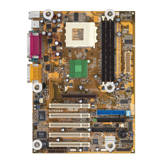
Page 15: Component Locations
1.4.1 Component Locations ASUS A7S333 motherboard user guide... -
Page 17: Chapter 2: Hardware Information
Chapter 2 Hardware information... - Page 18 ASUS A7S333 motherboard...
-
Page 19: Motherboard Installation
Motherboard installation The A7S333 uses the ATX form factor, measuring 21.9 cm (8.6 in.) x 30.5 cm (12 in.) - a standard fit for most large chassis. WARNING! Unplug the power cord before installing the motherboard. Failure to do so may cause you physical injury and damage motherboard components. - Page 20 T: USB1 B: USB2 COM1 COM2 Line Chipset Line BCS1 BCS2 Accelerated Graphics Port MODEM FP_AUDIO PCI1 FP_LO_SWR PRI_IDE FP_LO_SWL ® A7S333 PCI2 SEC_IDE AUDIO_EN PCI3 FLOPPY CHA_FAN SPDIF SMARTCON CR2032 3V Super Lithium Cell PCI4 CMOS Power CLRTC RTL8801 2Mbit...
-
Page 21: Layout Contents
31 IDE Connectors (Two 40-1 pin) 11) CPU_,PWR_,CHA_FAN p. 32 CPU, Power, and Chassis Fan Connectors (Three 3 pin) 12) AFPANEL p. 33 ASUS iPanel / Infrared Connector (24-1 pin) 13) ATXPWR p. 34 ATX Power Supply Connector (20 pin) 14) SMB p. - Page 22 22) PLED (PANEL) p. 39 System Power LED Lead (3-1 pin) 23) SPEAKER (PANEL) p. 39 System Warning Speaker Lead (4 pin) 24) MLED (PANEL) p. 39 System Message LED Lead (2 pin) 25) SMI (PANEL) p. 39 System Management Interrupt Lead (2 pin) 26) PWRBTN PANEL) p.
-
Page 23: Before You Proceed
NOTE! When lit, the onboard LED indicates that the system is ON, in sleep mode or in soft-off mode, not powered OFF. See the illustration below. SB_PWR ® A7S333 Standby Powered Power A7S333 Onboard LED ASUS A7S333 motherboard user guide... -
Page 24: Central Processing Unit (Cpu)
The motherboard provides a Socket A (462) for CPU installation. AMD processors offer gigahertz speeds to support all the latest computing platforms ™ and applications. The A7S333 supports Athlon XP processors with “QuantiSpeed” data processing, large data caches, 3D enhancements and 266Mhz bus speeds. -
Page 25: Installing The Cpu
CPU, make sure that exposed CPU capacitors do not touch the heatsink, or damage may occur! NOTE! Do not neglect to set the correct Bus Frequency and leave the CPU Multiple setting at default to avoid start-up problems. ASUS A7S333 motherboard user guide... -
Page 26: System Memory
DO NOT force a DIMM into a socket to avoid damaging the DIMM. • DIMMs with more than 18 chips are not supported. • ASUS motherboards support SPD (Serial Presence Detect)DIMMs. This is the memory of choice for best performance vs. stability • BIOS shows DDR SDRAM memory on bootup screen. -
Page 27: Memory Configurations
Use only the tested and qualified PC2700 - DDR333 DIMMs listed above. Other DDR DIMMs manufactured by other vendors may not be suitable for this motherboard. Visit the ASUS website for the latest qualified DDR module list. ASUS A7S333 motherboard user guide... -
Page 28: Installing A Dimm
2.5.4 Installing a DIMM CAUTION! Make sure to unplug the power supply before adding or removing DIMMs or other system components. Failure to do so may cause severe damage to both the motherboard and the components. Installing a DIMM: 1. Unlock a DIMM socket by pressing the retaining clips outward. 2. -
Page 29: Expansion Slots
IRQ will be used. If your motherboard also has MIDI enabled, another IRQ will be used, leaving 4 IRQs free. Sometimes IRQs are “shared” by more than one function; in this case, IRQ assignments are swapped automatically or adjusted through the BIOS firmware. ASUS A7S333 motherboard user guide... -
Page 30: Standard Interrupt Assignments
IMPORTANT! When using PCI cards on shared slots, ensure that the drivers support “Share IRQ” or that the cards do not need IRQ assignments. Otherwise, conflicts will arise between the two PCI groups, making the system unstable and the card inoperative. Standard Interrupt Assignments Priority Standard Function... -
Page 31: Pci Slots
+1.5V AGP card. ® A7S333 Keyed for 1.5v A7S333 Accelerated Graphics Port (AGP) CAUTION! To avoid damaging your AGP/AGP Pro graphics card, your computer’s power supply should be unplugged before inserting your graphics card into the slot. -
Page 32: Amr Slot (Optional)
There are two types of AMR, one defined as primary and another defined as secondary. You can only use primary AMRs with this motherboard. NOTE: An AMR is not included with this motherboard. ® A7S333 A7S333 Audio Modem Riser (AMR) Connector Chapter 2: Hardware information... -
Page 33: Switches And Jumpers
JumperFree™ mode allows processor settings to be made through the BIOS setup. ® A7S333 Jumper Mode Jumper Free (Default) A7S333 JumperFree™ Mode Setting NOTE! The JEN jumper is set in conjunction with the DIP switches. In JumperFree™ mode, set all DIP switches (DIP_SW) to OFF. ASUS A7S333 motherboard user guide... - Page 34 (or, BUS Clock) and the DRAM memory speed. ® A7S333 133MHz 100MHz 133MHz 133MHz 100MHz DRAM 166MHz 133MHz 100MHz 133MHz 100MHz A7S333 CPU External Frequency Selection Frequency Table DRAM [OFF] [OFF] [ON] [ON] [ON] [ON] [ON] [OFF] [OFF] [ON] [ON]...
- Page 35 (The computer will not power ON if you set this to [2-3] but do not have the correct ATX power supply.) KBPWR +5VSB (Default) ® A7S333 A7S333 Keyboard Power Setting NOTE! This jumper must be set in conjunction with Wake On PS2 KB/ PS2 Mouse/CIR in 4.5.1 Power Up Control. ASUS A7S333 motherboard user guide...
- Page 36 USBPWR_34 USBPWR_56 ® A7S333 +5VSB A7S333 USB Device Wake Up (Default) NOTE! This feature requires an ATX power supply that can supply at least 2A on the +5VSB lead when these jumpers are set to +5VSB. Otherwise, the system does not power up. The total current consumed must NOT exceed the power supply capability (+5VSB) whether under normal working conditions or in sleep mode.
- Page 37 The default, [2-3], enables the audio setting. Disable the onboard audio system if using a PCI audio card on any of the expansion slots. AUDIO_EN ® A7S333 Enable Disable (Default) A7S333 Audio Codec Setting ASUS A7S333 motherboard user guide...
- Page 38 Plug the power cord and turn ON the computer. Hold down the <Del> key during the boot process and enter BIOS setup to re-enter data. CLRTC ® A7S333 Clear CMOS Normal A7S333 Clear RTC RAM (Default) Chapter 2: Hardware information...
-
Page 39: Connectors
This connection is for a standard keyboard using an PS/2 plug (mini DIN). This connector does not allow standard AT size (large DIN) keyboard plugs. You may use a DIN to mini DIN adapter on standard AT keyboards. PS/2 Keyboard (6-pin Female) ASUS A7S333 motherboard user guide... - Page 40 3) Universal Serial Bus Ports 1 and 2 (Black two x 4-pin USB) Two USB ports are available for connecting USB devices. USB 1 Universal Serial Bus (USB) 2 4) Parallel Port (Burgundy 25-pin LPT) You can enable the parallel port and choose the IRQ through Onboard Parallel Port (see 4.4.2 I/O Device Configuration).
- Page 41 NOTE! The functions of the audio connectors Line Out, Line In, and Mic change when the 6-channel audio feature is enabled. Refer to Chapter 5. SOFTWARE SETUP. Line Out Line In 1/8" Stereo Audio Connectors ASUS A7S333 motherboard user guide...
- Page 42 (Pin 5 is removed to prevent inserting in the wrong orientation when using ribbon cables with pin 5 plugged). FLOPPY NOTE: Orient the red markings on the floppy ribbon cable to PIN 1. ® A7S333 PIN 1 A7S333 Floppy Disk Drive Connector Chapter 2: Hardware information...
- Page 43 IMPORTANT! UltraDMA100 IDE devices require a 40-pin 80-conductor cable. PRI_IDE Connector PIN 1 SEC_IDE Connector ® A7S333 NOTE: Orient the red markings (usually zigzag) on the IDE ribbon cable to PIN 1. A7S333 IDE Connectors ASUS A7S333 motherboard user guide...
- Page 44 (Use the “Rotation” signal only with a specially designed fan with a rotation signal. You can monitor the Rotations Per Minute (RPM) using ASUS PC Probe (see 5. Software Support). WARNING! Make sure to connect the fan cables to the fan connectors.
- Page 45 12) ASUS iPanel / Infrared Connector (24-1 pin AFPANEL) This connector supports an optional ASUS iPanel, an easy to access drive bay with front I/O ports, status LEDs, and space reserved for a hard disk drive. Alternatively, if not using an ASUS iPanel, connect an optional wireless transmitting and receiving infrared module to the SIR connector for wireless transmitting/remote control functions through an external infrared module.
- Page 46 +3.3VDC -12.0VDC +3.3VDC +3.3VDC A7S333 ATX Power Connectors 14) SMBus Connector (6-1 pin SMB) This connector supports SMBus (System Management Bus) devices. SMBus devices communicate by means of the SMBus with an SMBus host and/or other SMBus devices. SMBus is a multi-device bus that permits multiple chips to connect to the same bus and enable each one to act as a master by initiating data transfer.
- Page 47 Ground Modem-In A7S333 Internal Audio Connectors 16) Front Panel Audio Connector (10-1 pin FP_AUDIO) (on audio models only) This connector supports audio control to the front panel. FP_AUDIO ® A7S333 A7S333 Front Panel Audio Connector ASUS A7S333 motherboard user guide...
- Page 48 This header supports an IEEE-1394 serial connector cable set that mounts to a standard expansion slot in the computer case. 1394-compliant internal fixed disk drives may also be connected to these headers. IEEE-1394_1 IEEE-1394_2 IEEE-1394_3 ® A7S333 A7S333 IEEE-1394 Headers Chapter 2: Hardware information...
- Page 49 USB connector set to a USB header and mount the USB bracket to an open slot in the chassis. (The USB connector set is optional and does not come with the motherboard package.) USB_56 USB_34 ® A7S333 A7S333 Front Panel USB Headers ASUS A7S333 motherboard user guide...
- Page 50 Line Out jack and the Intel audio cable. FP_LINE_IN ® A7S333 A7S333 LINE_IN Connector IMPORTANT! The motherboard ships with Jumper caps over pins 1-2 and 4-5. Remove them only when making audio input connections.
- Page 51 ON mode for more than 4 seconds turns the system off. 27) Reset Switch Lead (2-pin RESET) This 2-pin connector supports the case-mounted reset switch for rebooting the system without turning off the power switch. ASUS A7S333 motherboard user guide...
- Page 52 Chapter 2: Hardware information...
-
Page 53: Chapter 3: Powering Up
Chapter 3 Powering up... - Page 54 ASUS A7S333 motherboard...
-
Page 55: Starting Up For The First Time
System running at a lower frequency You will not hear the BIOS beeps when the ASUS POST Reporter is enabled. You will hear the vocal POST messages instead. 7. At power on, hold down <Delete> to enter BIOS Setup. Follow the instructions in Chapter 4. -
Page 56: Powering Off The Computer
3.2 Powering off the computer You must first exit the operating system and shut down the system before switching off the power. For ATX power supplies, you can press the ATX power switch after exiting or shutting down the operating system. If you use Windows 95/98/2000/XP, click the Start button, click Shut Down, then click the OK button to shut down the computer. -
Page 57: Chapter 4: Bios Setup
Chapter 4 BIOS setup... - Page 58 ASUS A7S333 motherboard...
-
Page 59: Managing And Updating Your Bios
IMPORTANT! If the word “unknown” appears after Flash Memory:, the memory chip is either not programmable or is not supported by the ACPI BIOS and therefore, cannot be programmed by the Flash Memory Writer utility. ASUS A7S333 motherboard user guide... - Page 60 5. Select 1. Save Current BIOS to File from the Main menu and press <Enter>. The Save Current BIOS To File screen appears. 6. Type a filename and the path, for example, A:\XXX-XX.XXX, then press <Enter>. Chapter 4: BIOS Setup...
-
Page 61: Updating Bios Procedures
BIOS revision will solve your problems. Careless updating may result to more problems with the motherboard! 1. FTP) (see ASUS CONTACT INFORMATION on page x for details) and save to the boot floppy disk you created earlier. 2. Boot from the floppy disk. - Page 62 BIOS file you saved to the boot disk. If the Flash Memory Writer utility is not able to successfully update a complete BIOS file, the system may not boot. If this happens, call the ASUS service center for support. Chapter 4: BIOS Setup...
-
Page 63: Bios Setup Program
NOTE! Because the BIOS software is constantly being updated, the following BIOS setup screens and descriptions are for reference purposes only, and may not exactly match what you see on your screen. ASUS A7S333 motherboard user guide... -
Page 64: Bios Menu Bar
4.2.1 BIOS menu bar The top of the screen has a menu bar with the following selections: MAIN Use this menu to make changes to the basic system configuration. ADVANCED Use this menu to enable and make changes to the advanced features. -
Page 65: Scroll Bar
<F5> to load the Setup default values. While moving around through the Setup program, note that explanations appear in the Item Specific Help window located to the right of each menu. This window displays the help text for the currently highlighted field. ASUS A7S333 motherboard user guide... -
Page 66: Main Menu
Main Menu When you enter the Setup program, the following screen appears. System Time [XX:XX:XX] Sets the system to the time that you specify (usually the current time). The format is hour, minute, second. Valid values for hour, minute and second are Hour: (00 to 23), Minute: (00 to 59), Second: (00 to 59). -
Page 67: Primary And Secondary Master/Slave
Before attempting to configure a hard disk drive, make sure you have the correct configuration information supplied by the drive manufacturer. Incorrect settings may cause the system to fail to recognize the installed hard disk. ASUS A7S333 motherboard user guide... - Page 68 [User Type HDD] Manually enter the number of cylinders, heads and sectors per track for the drive. Refer to the drive documentation or on the drive label for this information. NOTE! After entering the IDE hard disk drive information into BIOS, use a disk utility, such as FDISK, to partition and format new IDE hard disk drives.
- Page 69 To make changes to this field, set the Type field to [User Type HDD]. Configuration options: [Disabled] [2 Sectors] [4 Sectors] [8 Sectors] [16 Sectors] [32 Sectors] [Maximum] ASUS A7S333 motherboard user guide...
- Page 70 SMART Monitoring [Disabled] This field allows you to enable or disable the S.M.A.R.T. (Self-Monitoring, Analysis and Reporting Technology) system that utilizes internal hard disk drive monitoring technology. This parameter is normally disabled because the resources used in the SMART monitoring feature may decrease system performance.
-
Page 71: Keyboard Features
Sec] [8/Sec] [10/Sec] [12/Sec] [15/Sec] [20/Sec] [24/Sec] [30/Sec] Keyboard Auto-Repeat Delay [1/4 Sec] This field sets the time interval for displaying the first and second characters. Configuration options: [1/4 Sec] [1/2 Sec] [3/4 Sec] [1 Sec] ASUS A7S333 motherboard user guide... -
Page 72: Forgot The Password
Language [English] This field displays the BIOS language version. Supervisor Password [Disabled] / User Password [Disabled] These fields allow you to set passwords. To set a password, highlight the appropriate field and press <Enter>. Type in a password then press <Enter>. You can type up to eight alphanumeric characters. -
Page 73: Advanced Menu
This field determines whether the memory clock frequency is set to be in synchronous or asynchronous mode with respect to the system frequency. The options that appear in the popup menu vary according to the CPU Frequency (MHz). Configuration options: [Auto] [1:1] [3:4] [4:3] [4:5] ASUS A7S333 motherboard user guide... - Page 74 CPU Level 1 Cache, CPU Level 2 Cache [Enabled] These fields selects the CPU Level 1 and Level 2 built-in cache. The default enables the caches. Configuration options: [Disabled] [Enabled] CPU Level 2 Cache EEC Check [Enabled] This fields sets up the check for the Level 2 built-in cache EEC check. Configuration options: [Disabled] [Enabled] BIOS Update [Enabled] This field functions as an update loader integrated into the BIOS to supply...
-
Page 75: Chip Configuration
SDRAM RAS Precharge Time [3T] This item controls the idle clocks after issuing a precharge command to the SDRAM. SDRAM RAS Active Time [6T] This item controls the clocks after issuing an active command to the SDRAM. ASUS A7S333 motherboard user guide... - Page 76 Graphics Aperture Size [64MB] This feature allows you to select the size of mapped memory for AGP graphic data. Configuration options: [4MB] [8MB] [16MB] [32MB] [64MB] [128MB] [256MB] AGP Capability [4X Mode] This motherboard supports the AGP 4X interface that transfers video data at 1066MB/s.
-
Page 77: I/O Device Configuration
Onboard Parallel Port [378H/IRQ7] This field sets the address of the onboard parallel port connector. If you disable this field, the Parallel Port Mode and ECP DMA Select configurations are not available. Configuration options: [Disabled] [378H/IRQ7] [278H/IRQ5] ASUS A7S333 motherboard user guide... - Page 78 Parallel Port Mode [ECP+EPP] This field allows you to set the operation mode of the parallel port. [Normal] allows normal-speed operation but in one direction only; [EPP] allows bidirectional parallel port operation; [ECP] allows the parallel port to operate in bidirectional DMA mode; [ECP+EPP] allows normal speed operation in a two-way mode.
-
Page 79: Pci Configuration
This field allows you to select the primary graphics card. Configuration options: [PCI VGA Card] [AGP VGA Card] USB Function [Enabled] Set this field to [Enabled] if you want to use Universal Serial Bus (USB) devices. Configuration options: [Disabled] [Enabled] ASUS A7S333 motherboard user guide... -
Page 80: Onboard Pci Devices Control
4.4.3.1 Onboard PCI Devices Control Onboard AC97 Audio Controller [Enabled] This parameter allows you to enable or disable the onboard AC97 audio controller. Configuration options: [Disabled] [Enabled] Onboard AC97 Modem Controller [Enabled] This parameter enables or disables the onboard Modem controller. Keep the setting [Enabled] if you wish to use the onboard Modem feature. -
Page 81: Pci Irq Resource Exclusion
IRQ is NOT required by a legacy ISA card. Set the IRQ field to [Yes] if you install a legacy ISA card that requires a unique IRQ and you are NOT using ICU. Configuration options: [No/ICU] [Yes] ASUS A7S333 motherboard user guide... - Page 82 4.4.3.3 Onboard DMA Resource Exclusion DMA x Reserved for Legacy Drive [No/ICU] These fields indicate whether or not the DMA channel displayed for each field is being used by a legacy (non-PnP) ISA card. The default setting indicates either that the DMA channel displayed is not used or an ICU is being used to determine if an ISA device is using the channel instead.
-
Page 83: Power Menu
Windows with the APM feature. In Windows 98 or later, APM is automatically installed as indicated by a battery and power cord icon labeled “Power Management” in the Control Panel. Select the item “Advanced” in the Power Management Properties dialog box. ASUS A7S333 motherboard user guide... - Page 84 Video Off Option [Suspend -> Off ] This field determines when to activate the video off feature for monitor power management. Configuration options: [Always On] [Suspend -> Off] Video Off Method [DPMS OFF] This field defines the video off features. The Display Power Management System (DPMS) feature allows the BIOS to control the video display card if it supports the DPMS feature.
-
Page 85: Power Up Control
Power Up On USB [Disabled] When set to [Enabled], the system through a network or a USB connection. This feature requires an ATX power supply that provides at least 1A on the +5VSB lead. Configuration options: [Disabled] [Enabled] ASUS A7S333 motherboard user guide... - Page 86 Power On By PS/2 Keyboard [Spacebar] This parameter allows you to use specific keys on the keyboard to turn on the system. This feature requires an ATX power supply that provides at least 1A on the +5VSB lead. Configuration options: [Disabled] [Space Bar] [Ctrl- Esc] [Power Key] Automatic Power Up [Disabled] This allows an unattended or automatic system power up.
-
Page 87: Hardware Monitor
If any of the monitored items is out of range, the following error message appears: “Hardware Monitor found an error. Enter Power setup menu for details”. You will then be prompted to “Press F1 to continue or DEL to enter SETUP”. ASUS A7S333 motherboard user guide... -
Page 88: Boot Menu
Boot Menu Boot Sequence The Boot menu allows you to select among the four possible types of boot devices listed using the up and down arrow keys. By using the <+> or <Space> key, you can promote devices and by using the <-> key, you can demote devices. - Page 89 This parameter offers a choice between PIC and APIC interrupt modes. The default is [APIC]. Configuration options: [Disabled] [Enabled] Full Screen Logo [Enabled] This field enables the display of the full screen logo that appears as the PC boots up. Configuration options: [Disabled] [Enabled] ASUS A7S333 motherboard user guide...
-
Page 90: Exit Menu
Exit Menu When you have made all of your selections from the various menus in the Setup program, save your changes and exit Setup. Select Exit from the menu bar to display the following menu. NOTE! Pressing <Esc> does not immediately exit this menu. Select one of the options from this menu or <F10>... -
Page 91: Discard Changes
This option saves your selections without exiting the Setup program. You can then return to other menus and make further changes. After you select this option, a confirmation window appears. Select [Yes] to save any changes to the non-volatile RAM. ASUS A7S333 motherboard user guide... - Page 92 Chapter 4: BIOS Setup...
-
Page 93: Chapter 5: Software Support
Chapter 5 Software support... - Page 94 ASUS A7S333 motherboard...
-
Page 95: Install An Operating System
NOTE! The contents of the support CD are subject to change at any time without notice. Visit the ASUS website for updates. 5.2.1 Running the support CD To begin using the support CD, simply insert the CD into your CD-ROM drive. -
Page 96: A7S333 Motherboard Support Cd
5.3 A7S333 Motherboard Support CD NOTE: The support CD contents are subject to change without notice. To begin using your support CD disc, just insert it into your CD-ROM drive and the support CD installation menu should appear. If the menu does not appear, double-click or run D:\ASSETUP.EXE. - Page 97 Software: • ASUS PC Probe: Installs a smart utility to monitor your computer’s fan, temperature, and voltages. • ASUS Update: Instals a program that can help you update BIOS or download a BIOS image file. • Microsoft DirectX Driver: Installs basic drivers to enable compatibility with audio and other special functions.
- Page 98 Chapter 5: Software support...
-
Page 99: Asus Pc Probe
ASUS Utility, and then click Probe Vx.xx. The PC Probe icon will appear on the taskbar’s system tray indicating that ASUS PC Probe is running. Clicking the icon will allow you to see the status of your PC. ASUS A7S333 motherboard user guide... -
Page 100: Using Asus Pc Probe
5.4.2 Using ASUS PC Probe Monitoring Monitor Summary Shows a summary of the items being monitored. Temperature Monitor Shows the PC’s temperature. Temperature Warning threshold adjustment (Move the slider up to increase the threshold level or down to decrease the threshold level) Fan Monitor Shows the PC’s fan rotation. - Page 101 PC for future reference. Information Hard Drives Shows the used and free space of the PC’s hard disk drives and the file allocation table or file system used. ASUS A7S333 motherboard user guide...
- Page 102 Shows information pertinent to the PC, such as CPU type, CPU speed, and internal/external frequencies, and memory size. Utility Lets you run programs outside of the ASUS Probe modules. To run a program, click Execute Program. Chapter 5: Software reference...
-
Page 103: Asus Pc Probe Task Bar Icon
5.4.3 ASUS PC Probe Task Bar Icon Right-clicking the PC Probe icon will bring up a menu to open or exit ASUS PC Probe and pause or resume all system monitoring. When the ASUS PC Probe senses a problem with your... -
Page 104: Asus Live Update
ASUS Live Update ASUS LiveUpdate is a utility that allows you to update your motherboard’s BIOS and drivers. The use of this utility requires that you are properly connected to the Internet through an Internet Service Provider (ISP). 1. Start ASUS Update. Launch the utility from your Windows Start menu:Programs/AsusUpdate. -
Page 105: 3Deep Color Tuner
1. Select the type of monitor connected to the computer, either CRT or LCD. 2. Follow the instructions to manually adjust the brightness level of the monitor. 3. Select the faintest of the three colors: blue, red and green. ASUS A7S333 motherboard user guide... -
Page 106: The 3Deep Control Panel
4. Select the color squares which most closely blend and match with the background. 5. The next step repeats the color matching process to achieve full color quality. 6. The tuning process is complete. Click on the bottom left button to connect to the internet and follow the instructions. -
Page 107: Ite Gsm Editor
5.7.1 Setting Up ITE GSM Editor Connect a smart card reader to the A7S333; (refer to page 36 in Hardware Setup for the connector location.) Boot-up the PC and enter BIOS (press <del>) to change the configuration to accept smart card hardware: in the Advanced BIOS menu select the I/O Device Configuration sub-menu, go to UART2 Function Selection and choose Smart Card Read, save and exit. - Page 108 5.7.2 The ITE GSM Menu: 5.7.3 Using the basic ITE GSM Editor: 1. Carefully remove the SIM chip from your mobile phone and insert it into the card reader. The most convenient method is to use a conversion card: slip the SIM chip into the conversion card and then insert it into the card reader.
- Page 109 Phone number entries may be comprised of: “1, 2, 3, 4, 5, 6, 7, 8, 9, #, *, C, or +”. Pressing “C” commands the dialer to pause for three seconds before dialing the next digit; the “C” code is useful for dialing extension numbers. Pressing “+” indicates the international head code. ASUS A7S333 motherboard user guide...
- Page 110 5.7.5 Using the PIN Manager: 1. Enable PIN Set-Up: This function is used to set the PIN. This function is effective only if the PIN set-up is disabled and the SIM card is not blocked. First enter the PIN set previously to enable the PIN set-up function. New users may find the default PIN in the SIM card user manual.
-
Page 111: Cyberlink Powerplayer Se
Backstep Frame Step Frame Previous Next Play Stop Configuration i-Power! Increase Volume CD Mode Mute Shuffle Decrease Volume Karaoke Next angle Next audio stream Next subtitle Add bookmark Capture frame Go-Up Repeat Menu Go to bookmark ASUS A7S333 motherboard user guide... -
Page 112: Cyberlink Videolive Mail
5.9 CyberLink VideoLive Mail CyberLink’s VideoLive Mail Plus Ver 3.0 (a.k.a. VLM 3) is a convenient and excellent way to create professional quality video mails from PC video/audio input devices and to send the mails to any recipients via VLM 3’s built-in e- mail system through the Internet. -
Page 113: Starting Videolive Mail
Start Playback Save Video File Snapshot to File Stop Recording / Playback Send Mail Start Recording Video Configuration Load Video File Pause Send Mail Increase MIC volume Decrease MIC volume Increase speaker volume Decrease speaker volume ASUS A7S333 motherboard user guide... - Page 114 Chapter 5: Software reference...
-
Page 115: Glossary
Glossary... - Page 116 ASUS A7S333 motherboard...
- Page 117 When the manual instructs you to “boot” your system (or computer), it means to turn ON your computer. “Reboot” means to restart your computer. When using Windows 95 or later, selecting “Restart” from “Start | Shut Down...” will reboot your computer. ASUS A7S333 motherboard user guide...
- Page 118 Bus Master IDE PIO (Programmable I/O) IDE requires that the CPU be involved in IDE access and waiting for mechanical events. Bus master IDE transfers data to/from the memory without interrupting the CPU. Bus master IDE driver and bus master IDE hard disk drives are required to support bus master IDE mode.
- Page 119 I/O devices. PS/2 Port PS/2 ports are based on IBM Micro Channel Architecture. This type of architecture transfers data through a 16-bit or 32-bit bus. A PS/2 mouse and/or keyboard may be used on ATX motherboards. ASUS A7S333 motherboard user guide...
- Page 120 RDRAM (Rambus DRAM) Developed by Rambus, Inc., this type of memory can deliver up to 1.6GB of data per second. RDRAM is the first interface standard that can be directly implemented on high performance VLSI components such as, CMOS DRAMs, memory controllers, and graphics/video ICs.
-
Page 121: Index
Index... - Page 122 ASUS A7S333 motherboard...
- Page 123 VideoLive Mail 94 Sub-menu launching 49 CyberLink PowerPlayer SE Updating 43 Using 93 BIOS Beep Codes 41 CyberLink VideoLive Mail Boot Device Using 94 Selection 72 Boot Up NumLock Status 55 Boot Virus Detection 73 ASUS A7S333 motherboard user guide...
- Page 124 Bass Center setting 25 Cleaer RTC RAM 26 DIMM CPU and DRAM DSW 22 installing 16 Keyboard Wake Up 23 DIP Switches 21 USB device wake-up 24 expansion card Keyboard installation 17 Auto-Repeat Delay 55 Expansion slots 17 Auto-Repeat Rate 55 Connector 27 Features 55 Floppy 3 Mode 50...
- Page 125 Serial Ports 61 Connectors 28 slots AGP 19 CNR 20 PCI 19 Smart Card Reader 36 SMART Monitoring 54 SMBus Connector 34 Support CD 77 Welcome screen 77 System Date 50 System memory configurations 14 ASUS A7S333 motherboard user guide...
- Page 126 Index...