Table of Contents
Advertisement
Advertisement
Table of Contents

Related Manuals for Asus P5KPL-AM EPU


Summary of Contents for Asus P5KPL-AM EPU
- Page 1 P5KPL-AM EPU...
- Page 2 Product warranty or service will not be extended if: (1) the product is repaired, modified or altered, unless such repair, modification of alteration is authorized in writing by ASUS; or (2) the serial number of the product is defaced or missing.
-
Page 3: Table Of Contents
Contents Notices ......................vi Safety information ..................vii About this guide ..................vii P5KPL-AM EPU specifications summary ..........ix Chapter 1: Product introduction Welcome! ..................1-1 Package contents ................. 1-1 Special features ................1-1 1.3.1 Product highlights ............1-1 1.3.2 Innovative ASUS features .......... - Page 4 BIOS information Managing and updating your BIOS ..........2-1 2.1.1 ASUS Update utility ............2-1 2.1.2 ASUS EZ Flash 2 utility ........... 2-2 2.1.3 ASUS CrashFree BIOS 3 utility ........2-3 BIOS setup program ..............2-4 2.2.1 BIOS menu screen ............2-5 2.2.2...
- Page 5 Boot menu .................. 2-17 2.6.1 Boot Device Priority ............2-17 2.6.2 Boot Settings Configuration .......... 2-18 2.6.3 Security ................. 2-18 Tools menu ................. 2-20 2.7.1 ASUS EZ Flash 2 ............2-20 2.7.2 AI NET 2................ 2-20 Exit menu ..................2-21...
-
Page 6: Notices
Complying with the REACH (Registration, Evaluation, Authorisation, and Restriction of Chemicals) regulatory framework, we published the chemical substances in our products at ASUS REACH website at http://green.asus.com/english/REACH.htm. DO NOT throw the motherboard in municipal waste. This product has been designed to enable proper reuse of parts and recycling. -
Page 7: Safety Information
DO NOT throw the mercury-containing button cell battery in municipal waste. This symbol of the crossed out wheeled bin indicates that the battery should not be placed in municipal waste. Safety information Electrical safety • To prevent electrical shock hazard, disconnect the power cable from the electrical outlet before relocating the system. -
Page 8: Conventions Used In This Guide
Refer to the following sources for additional information and for product and software updates. ASUS websites The ASUS website provides updated information on ASUS hardware and software products. Refer to the ASUS contact information. Optional documentation Your product package may include optional documentation, such as warranty flyers, that may have been added by your dealer. -
Page 9: P5Kpl-Am Epu Specifications Summary
P5KPL-AM EPU specifications summary LGA775 Socket for Intel Core™2 Extreme /Core™2 Quad / ® Core™2 Duo / Pentium dual-core / Celeron dual-core / ® ® Celeron processors ® Supports Intel 45nm multi-core CPU ® Intel Hyper-Threading Technology ready ® Support Enhanced Intel SpeedStep Technology (EIST) (Refer to www.asus.com for Intel... - Page 10 P5KPL-AM EPU specifications summary Rear panel ports 1 x PS/2 keyboard port 1 x PS/2 mouse port 1 x LAN (RJ-45) port 4 x USB 2.0/1.1 ports 6-channel audio I/O port 1 x VGA port 1 x COM port 1X Parallel port...
-
Page 11: Chapter 1: Product Introduction
® The motherboard delivers a host of new features and latest technologies, making it another standout in the long line of ASUS quality motherboards! Before you start installing the motherboard, and hardware devices on it, check the items in your package with the list below. -
Page 12: Innovative Asus Features
Turbo Key ASUS Turbo Key allows you to turn the PC power button into an overclocking button. After you easy setup, Turbo Key boosts performances without interrupting ongoing work or games, simply through pressing the button. -
Page 13: Asus Mylogo2
BIOS file using the bundled support DVD or USB disk that contains the latest BIOS file. ASUS EZ Flash 2 ASUS EZ Flash 2 is a utility that allows you to update the BIOS without using an OS-based utility. ASUS AI NET2... -
Page 14: Before You Proceed
Before you proceed Take note of the following precautions before you install motherboard components or change any motherboard settings. • Unplug the power cord from the wall socket before touching any component. • Before handling components, use a grounded wrist strap or touch a safely grounded object or a metal object, such as the power supply case, to avoid damaging them due to static electricity. -
Page 15: Motherboard Overview
Screw holes Place six screws into the holes indicated by circles to secure the motherboard to the chassis. Do not overtighten the screws! Doing so can damage the motherboard. Place this side towards the rear of the chassis ASUS P5KPL-AM EPU... -
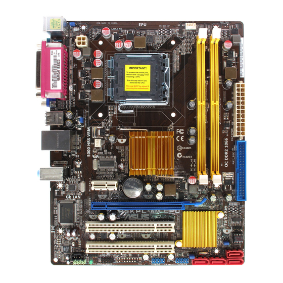
Page 16: Motherboard Layout
1.5.3 Motherboard layout 1.5.4 Layout contents Connectors/Jumpers/Slots Page Connectors/Jumpers/Slots Page Keyboard power (3-pin KBPWR) 1-20 Speaker connector (4-pin SPEAKER) 1-26 ATX power connectors (24-pin EATXPWR, 4-pin 1-23 Serial ATA connectors (7-pin SATA1-4) 1-24 ATX12V) USB device wake-up (3-pin USBPW1-4, 1-20 USB connectors (10-1 pin USB56, USB78) 1-27 USBPW5-8) -
Page 17: Central Processing Unit (Cpu)
Contact your retailer immediately if the PnP cap is missing, or if you see any damage to the PnP cap/socket contacts/motherboard components. ASUS will shoulder the cost of repair only if the damage is shipment/transit-related. • Keep the cap after installing the motherboard. ASUS will process Return Merchandise Authorization (RMA) requests only if the motherboard comes with the cap on the LGA775 socket. - Page 18 Press the load lever with your thumb Retention tab (A), then move it to the left (B) until it is released from the retention tab. To prevent damage to the socket pins, do not remove the PnP cap unless you are installing a CPU. Load lever Lift the load lever in the direction of the PnP cap...
- Page 19 To prevent contaminating the paste, DO NOT spread the paste with your finger directly. Close the load plate (A), then push the load lever (B) until it snaps into the retention tab. ASUS P5KPL-AM EPU...
-
Page 20: Installing The Cpu Heatsink And Fan
1.6.2 Installing the CPU heatsink and fan The Intel LGA775 processor requires a specially designed heatsink and fan assembly to ® ensure optimum thermal condition and performance. • When you buy a boxed Intel processor, the package includes the CPU fan and ®... -
Page 21: Uninstalling The Cpu Heatsink And Fan
Disconnect the CPU fan cable from the connector on the motherboard. Rotate each fastener counterclockwise. Pull up two fasteners at a time in a diagonal sequence to disengage the heatsink and fan assembly from the motherboard. ASUS P5KPL-AM EPU 1-11... -
Page 22: System Memory
Carefully remove the heatsink and fan assembly from the motherboard. Rotate each fastener clockwise to ensure correct orientation when reinstalling. System memory 1.7.1 Overview The motherboard comes with two Double Data Rate 2 (DDR2) Dual Inline Memory Modules (DIMM) sockets. The figure illustrates the location of the DDR2 DIMM sockets: Channel Sockets Channel A... -
Page 23: Memory Configurations
ODT value. • Due to chipset limitation, DDR2-800 with CL=4 will be downgraded to run at DDR2-667 by default setting. If you want to operate with lower latency, adjust the memory timing manually. ASUS P5KPL-AM EPU 1-13... - Page 24 P5KPL-AM EPU Motherboard Qualified Vendors Lists (QVL) DDR2-1066 MHz capability DIMM support Size Vendor Model Brand SS/DS Component 512MB Kingston KHX8500D2/512 Kingston Heat-Sink Package • • 512MB Kingston KHX8500D2K2/1GN Kingston Heat-Sink Package • • Kingston KHX8500D2K2/2GN Kingston Heat-Sink Package •...
- Page 25 ADATA AD29608A8A-3EG20648 • • 512MB ADATA M20AD5G3H3166I1C52 ADATA AD29608A8A-3EG20718 • • ADATA M2OAD5G3I4176I1C52 ADATA AD29608A8A-3EG20645 • • 512MB VDATA M2GVD5G3H31A4I1C52 VDATA VD29608A8A-3EC20615 • • 512MB VDATA M2YVD5G3H31P4I1C52 VDATA VD29608A8A-3EG20627 • • (continued on the next page) ASUS P5KPL-AM EPU 1-15...
- Page 26 • A*: Supports one module inserted into any slot as Single-channel memory configuration. • B*: Supports one pair of modules inserted into both the yellow slots as one pair of Dual-channel memory configuration. Visit the ASUS website at www.asus.com for the latest QVL. 1-16 Chapter 1: Product introduction...
-
Page 27: Installing A Dimm
DIMM. Support the DIMM lightly with your fingers when pressing the retaining clips. The DIMM might get damaged when it flips out with extra force. DDR2 DIMM notch Remove the DIMM from the socket. ASUS P5KPL-AM EPU 1-17... -
Page 28: Expansion Slots
Expansion slots In the future, you may need to install expansion cards. The following sub-sections describe the slots and the expansion cards that they support. Unplug the power cord before adding or removing expansion cards. Failure to do so may cause you physical injury and damage motherboard components. -
Page 29: Clear Rtc Ram
• Due to the chipset limitation, AC power off is required before you use the C.P.R. function. You must turn off and on the power supply or unplug and plug the power cord before rebooting the system. ASUS P5KPL-AM EPU 1-19... - Page 30 USB device wake-up (3-pin USBPW1-4, USBPW5-8) Set the jumpers to +5V to wake up the computer from S1 sleep mode (CPU stopped, DRAM refreshed, system running in low power mode) using the connected USB devices. Set to +5VSB to wake up from S3 and S4 sleep modes (no power to CPU, DRAM in slow refresh, power supply in reduced power mode).
-
Page 31: Connectors
Audio 2, 4, or 6-channel configuration Port Headset 2-channel 4-channel 6-channel Light Blue Line In Rear Speaker Out Rear Speaker Out Lime Line Out Front Speaker Out Front Speaker Out Pink Mic In Mic In Bass/Center ASUS P5KPL-AM EPU 1-21... -
Page 32: Internal Connectors
Do not forget to connect the fan cables to the fan connectors. Insufficient air flow inside the system may damage the motherboard components. These are not jumpers! Do not place jumper caps on the fan connectors! Only the CPU fan supports the ASUS Q-FAN feature. 1-22 Chapter 1: Product introduction... - Page 33 This connector is for an additional Sony/Philips Digital Interface (S/PDIF) port. Connect the S/PDIF Out module cable to this connector, then install the module to a slot opening at the back of the system chassis. The S/PDIF module is purchased separately. ASUS P5KPL-AM EPU 1-23...
- Page 34 Serial ATA connectors (7-pin SATA1-4) These connectors are for the Serial ATA signal cables for Serial ATA hard disk drives. Install the Windows XP Service Pack 2 or later version before using Serial ATA. ® Optical drive audio connector (4-pin CD) This connector allows you to receive stereo audio input from sound sources such as a CD-ROM, TV tuner, or MPEG card.
- Page 35 This prevents incorrect insertion when you connect the IDE cable. • Use the 80-conductor IDE cable for Ultra DMA 100/66/33 IDE devices. If any device jumper is set as “Cable-Select,” ensure that all other device jumpers have the same setting. ASUS P5KPL-AM EPU 1-25...
-
Page 36: System Panel Connector
System panel connector (10-1 pin F_PANEL) This connector supports several chassis-mounted functions. • System power LED (2-pin PLED) This 2-pin connector is for the system power LED. Connect the chassis power LED cable to this connector. The system power LED lights up when you turn on the system power, and blinks when the system is in sleep mode. -
Page 37: Usb Connectors
Front Panel Support Type item in the BIOS setup to [HD Audio]. If you want to connect an AC'97 front panel audio module to this connector, set the item to [AC97]. By default, this connector is set to [HD Audio]. See section 2.4.3 Chipset for details. ASUS P5KPL-AM EPU 1-27... -
Page 38: Software Support
The contents of the Support DVD are subject to change at any time without notice. Visit the ASUS website at www.asus.com for updates. To run the Support DVD Place the Support DVD to the optical drive. -
Page 39: Managing And Updating Your Bios
BIOS in the future. Copy the original motherboard BIOS using the ASUS Update utility. 2.1.1 ASUS Update utility The ASUS Update is a utility that allows you to manage, save, and update the motherboard BIOS in Windows environment. ®... -
Page 40: Asus Ez Flash 2 Utility
Follow the onscreen instructions to complete the updating process. 2.1.2 ASUS EZ Flash 2 utility The ASUS EZ Flash 2 feature allows you to update the BIOS without using an OS-based utility. Before you start using this utility, download the latest BIOS file from the ASUS website at www.asus.com. -
Page 41: Asus Crashfree Bios 3 Utility
2.1.3 ASUS CrashFree BIOS 3 utility The ASUS CrashFree BIOS 3 is an auto recovery tool that allows you to restore the BIOS file when it fails or gets corrupted during the updating process. You can update a corrupted BIOS file using the motherboard support DVD or a USB flash disk that contains the updated BIOS file. -
Page 42: Bios Setup Program
Restart the system after the utility completes the updating process. • Only a USB flash disk with FAT 32/16 format and single partition can support ASUS CrashFree BIOS 3. The device size should be smaller than 8GB. • DO NOT shut down or reset the system while updating the BIOS! Doing so can cause system boot failure! The recovered BIOS may not be the latest BIOS version for this motherboard. -
Page 43: Bios Menu Screen
• The BIOS setup screens shown in this section are for reference purposes only, and may not exactly match what you see on your screen. • Visit the ASUS website at www.asus.com to download the latest BIOS file for this motherboard. -
Page 44: Navigation Keys
2.2.3 Navigation keys At the bottom right corner of a menu screen are the navigation keys for that particular menu. Use the navigation keys to select items in the menu and change the settings. Some of the navigation keys differ from one screen to another. 2.2.4 Menu items The highlighted item on the menu bar displays the specific items for that menu. -
Page 45: Main Menu
IDE device type. Select [CDROM] if you are specifically configuring a CD-ROM drive. Select [ARMD] (ATAPI Removable Media Device) if your device is either a ZIP, LS-120, or MO drive. Configuration options: [Not Installed] [Auto] [CDROM] [ARMD] This item does not appear if you select SATA 1/2/3/4 devices. ASUS P5KPL-AM EPU... -
Page 46: Storage Configuration
LBA/Large Mode [Auto] Enables or disables the LBA mode. Setting to [Auto] enables the LBA mode if the device supports this mode, and if the device was not previously formatted with LBA mode disabled. Configuration options: [Disabled] [Auto] Block (Multi-sector Transfer) M [Auto] Enables or disables data multi-sectors transfers. -
Page 47: System Information
Manual - allows you to individually set overclocking parameters. Auto - loads the optimal settings for the system. Overclock Profile - loads overclocking profiles with optimal parameters for stability when overclocking. Test Mode - loads the test mode. ASUS P5KPL-AM EPU... - Page 48 The following item appears only when you set the AI Overclocking item to [Manual]. CPU Frequency [xxx] Displays the frequency sent by the clock generator to the system bus and PCI bus. The value of this item is auto-detected by the BIOS. Use the <+> and <-> keys to adjust the CPU frequency.
-
Page 49: Cpu Configuration
CPU TM function [Enabled] Enables or disables Intel CPU Thermal Monitor (TM) function, a CPU overheating ® protection function. When enabled, the CPU core frequency and voltage are reduced when the CPU overheats. Configuration options: [Disabled] [Enabled] ASUS P5KPL-AM EPU 2-11... -
Page 50: Chipset
Execute Disable Bit [Enabled] Allows you to enable or disable the No-Execution Page Protection Technology. Setting this item to [Disabled] forces the XD feature flag to always return to zero (0). Configuration options: [Disabled] [Enabled] The following item appears only when you installed an Intel CPU that supports the ®... -
Page 51: Onboard Devices Configuration
Appears only when the Parallel Port Mode is set to [ECP]. This item allows you to set the Parallel Port ECP DMA. Configuration options: [DMA0] [DMA1] [DMA3] Parallel Port IRQ [IRQ7] Allows you to select parallel port IRQ. Configuration options: [IRQ5] [IRQ7] ASUS P5KPL-AM EPU 2-13... -
Page 52: Usb Configuration
2.4.5 USB Configuration The items in this menu allows you to change the USB-related features. Select an item then press <Enter> to display the configuration options. The Module Version and USB Devices Enabled items show the auto-detected values. If no USB device is detected, the item shows None. -
Page 53: Pci Pnp
[Auto] - Detected by OS. 2.5.2 ACPI 2.0 Support [Disabled] Allows you to add more tables for Advanced Configuration and Power Interface (ACPI) 2.0 specifications. Configuration options: [Disabled] [Enabled] ASUS P5KPL-AM EPU 2-15... -
Page 54: Acpi Apic Support
2.5.3 ACPI APIC Support [Enabled] Allows you to enable or disable the Advanced Configuration and Power Interface (ACPI) support in the Application-Specific Integrated Circuit (ASIC). When set to Enabled, the ACPI APIC table pointer is included in the RSDT pointer list. Configuration options: [Disabled] [Enabled] 2.5.4 APM Configuration... -
Page 55: Hardware Monitor
These items specify the boot device priority sequence from the available devices. The number of device items that appears on the screen depends on the number of devices installed in the system. Configuration options: [Removable Dev.] [Hard Drive] [ATAPI CD-ROM] [Disabled] ASUS P5KPL-AM EPU 2-17... -
Page 56: Boot Settings Configuration
POST items. Configuration options: [Disabled] [Enabled] Full Screen Logo [Enabled] This allows you to enable or disable the full screen logo display feature. Configuration options: [Disabled] [Enabled] Set this item to [Enabled] to use the ASUS MyLogo2 feature. ™ AddOn ROM Display Mode [Force BIOS] Sets the display mode for option ROM. -
Page 57: Change User Password
Password Check [Setup] When set to [Setup], BIOS checks for user password when accessing the Setup utility. When set to [Always], BIOS checks for user password both when accessing Setup and booting the system. Configuration options: [Setup] [Always] ASUS P5KPL-AM EPU 2-19... -
Page 58: Tools Menu
2.7.1 ASUS EZ Flash 2 Allows you to run ASUS EZ Flash 2. When you press <Enter>, a confirmation message appears. Use the left/right arrow key to select between [Yes] or [No], then press <Enter> to confirm your choice. Please see section 2.1.2 for details. -
Page 59: Exit Menu
When you select this option or if you press <F5>, a confirmation window appears. Select OK to load default values. Select Exit & Save Changes or make other changes before saving the values to the non-volatile RAM. ASUS P5KPL-AM EPU 2-21... - Page 60 2-22 Chapter 2: BIOS information...