Table of Contents
Advertisement
Advertisement
Table of Contents

Related Manuals for Asus P5KPL-C/1600


Summary of Contents for Asus P5KPL-C/1600
- Page 1 P5KPL-C/1600...
- Page 2 Product warranty or service will not be extended if: (1) the product is repaired, modified or altered, unless such repair, modification of alteration is authorized in writing by ASUS; or (2) the serial number of the product is defaced or missing.
-
Page 3: Table Of Contents
Contents Notices ......................vi Safety information ..................vii About this guide ..................viii P5KPL-C/1600 specifications summary ............ x Chapter 1: Product introduction Welcome! ..................1-2 Package contents ................. 1-2 Special features ................1-3 1.3.1 Product highlights ............1-3 1.3.2 Innovative ASUS features ..........1-5 Before you proceed .............. - Page 4 Chapter 2: BIOS setup Managing and updating your BIOS ..........2-2 2.1.1 Creating a bootable floppy disk ........2-2 2.1.2 ASUS EZ Flash 2 utility ........... 2-4 2.1.3 AFUDOS utility ..............2-5 2.1.4 ASUS CrashFree BIOS 3 utility ........2-7 2.1.5...
- Page 5 2.6.2 Boot Settings Configuration .......... 2-33 2.6.3 Security ................. 2-34 Tools menu ................. 2-36 ASUS EZ Flash 2 ................ 2-36 Exit menu ..................2-37 Chapter 3: Software support Installing an operating system ........... 3-2 Support CD information .............. 3-2 3.2.1 Running the support CD ..........
-
Page 6: Notices
Notices Federal Communications Commission Statement This device complies with Part 15 of the FCC Rules. Operation is subject to the following two conditions: • This device may not cause harmful interference, and • This device must accept any interference received including interference that may cause undesired operation. -
Page 7: Safety Information
Safety information Electrical safety • To prevent electrical shock hazard, disconnect the power cable from the electrical outlet before relocating the system. • When adding or removing devices to or from the system, ensure that the power cables for the devices are unplugged before the signal cables are connected. -
Page 8: About This Guide
Refer to the following sources for additional information and for product and software updates. ASUS websites The ASUS website provides updated information on ASUS hardware and software products. Refer to the ASUS contact information. Optional documentation Your product package may include optional documentation, such as warranty flyers, that may have been added by your dealer. -
Page 9: Conventions Used In This Guide
Conventions used in this guide To make sure that you perform certain tasks properly, take note of the following symbols used throughout this manual. DANGER/WARNING: Information to prevent injury to yourself when trying to complete a task. CAUTION: Information to prevent damage to the components when trying to complete a task. -
Page 10: P5Kpl-C/1600 Specifications Summary
Supports Intel E64MT Technology ® Supports Enhanced Intel SpeedStep Technology (EIST) ® Refer to www.asus.com for Intel CPU support list Chipset Northbridge: Intel® G31 Southbridge: Intel® ICH7 Front Side Bus 1600 (O.C)* / 1333 / 1066 / 800 MHz Memory... - Page 11 P5KPL-C/1600 specifications summary Rear panel 1 x PS/2 keyboard port 1 x PS/2 mouse port 1 x Parallel port 1 x COM port 1 x LAN (RJ-45) port 4 x USB 2.0 / 1.1 ports 8-channel Audio I/O ports Internal connectors 2 x USB 2.0 connectors supports additional 4 USB 2.0...
-
Page 13: Chapter 1: Product Introduction
This chapter describes the motherboard features and the new technologies it supports. Product introduction... -
Page 14: Welcome
Thank you for buying an ASUS® P5KPL-C/1600 motherboard! The motherboard delivers a host of new features and latest technologies, making it another standout in the long line of ASUS quality motherboards! Before you start installing the motherboard, and hardware devices on it, check the items in your package with the list below. -
Page 15: Special Features
FSB 1600 support (O.C.) ASUS’s exclusive overclocking design now unleashes the ultimate potential of the Intel® Core™2 processor. With the new Intel 45nm micro-architecture technology and FSB 1600 (O.C.) / 1333 / 1066 / 800 MHz, this motherboard allows you to enjoy the latest technology supported by one of the most powerful and energy efficient CPUs in the world. - Page 16 PCI Express™ interface The motherboard fully supports PCI Express, the latest I/O interconnect technology that speeds up the PCI bus. PCI Express features point-to-point serial interconnections between devices and allows higher clockspeeds by carrying data in packets. This high speed interface is software compatible with existing PCI specifications.
-
Page 17: Innovative Asus Features
1.3.2 Innovative ASUS features ASUS CrashFree BIOS3 The ASUS CrashFree BIOS 3 allows users to restore corrupted BIOS data from a USB flash disk containing the BIOS file. See page 2-7 for details. ASUS Q-Fan technology The ASUS Q-Fan technology smartly adjusts the fan speeds according to the system loading to ensure quiet, cool, and efficient operation. -
Page 18: Asus Mylogo2
Green ASUS This motherboard and its packaging comply with the European Union’s Restriction on the use of Hazardous Substances (RoHS). This is in line with the ASUS vision of creating environment-friendly and recyclable products/packaging to safeguard consumers’ health while minimizing the impact on the environment. -
Page 19: Before You Proceed
The illustration below shows the location of the onboard LED. SB_PWR Standby Powered Power P5KPL-C/1600 Onboard LED ASUS P5KPL-C/1600... -
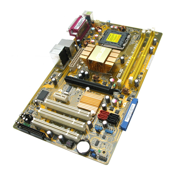
Page 20: Motherboard Overview
Motherboard overview Before you install the motherboard, study the configuration of your chassis to ensure that the motherboard fits into it. Ensure to unplug the power cord before installing or removing the motherboard. Failure to do so can cause you physical injury and damage motherboard components. -
Page 21: Motherboard Layout
SATA2 PCI1 USB56 USB78 USBPW5-8 PCI2 VT1708B PCI3 SB_PWR CR2032 3V CLRTC AAFP Lithium Cell FLOPPY SPEAKER CMOS Power BIOS SPDIF_OUT F_PANEL CHASSIS Refer to section 1.10 Connectors for more information about rear panel connectors and internal connectors. ASUS P5KPL-C/1600... -
Page 22: Layout Contents
1.5.4 Layout contents Slots Page DDR2 DIMM slots 1-18 PCI slots 1-26 PCI Express x 1 slot 1-26 PCI Express x 16 slot 1-26 Jumpers Page Clear RTC RAM (3-pin CLRTC) 1-27 USB device wake-up (3-pin USBPW) 1-28 Rear panel connectors Page PS/2 mouse port (green) 1-29... -
Page 23: Central Processing Unit (Cpu)
ASUS will shoulder the cost of repair only if the damage is shipment/transit-related. • Keep the cap after installing the motherboard. ASUS will process Return Merchandise Authorization (RMA) requests only if the motherboard comes with the cap on the LGA775 socket. - Page 24 Press the load lever with your thumb (A), then move it to the left (B) until it is released from the retention tab. Retention tab PnP cap Load lever This side of the socket box should face you. To prevent damage to the socket pins, do not remove the PnP cap unless you are installing a CPU.
- Page 25 The motherboard supports Intel LGA775 processors with the Intel Enhanced ® ® Intel SpeedStep Technology (EIST) and Hyper-Threading Technology. Refer to ® the Appendix for more information on these CPU features. ASUS P5KPL-C/1600 1-13...
-
Page 26: Installing The Cpu Heatsink And Fan
1.6.2 Installing the CPU heatsink and fan The Intel Prescott / Smithfield / Cedarmill / Conroe / Conroe L / Presler / Kentsfield ® / Yorkfield LGA775 processor requires a specially designed heatsink and fan assembly to ensure optimum thermal condition and performance. •... - Page 27 Connect the CPU fan cable to the connector on the motherboard labeled CPU_FAN. CPU_FAN P5KPL-C/1600 CPU Fan Connector Do not forget to connect the CPU fan connector! Hardware monitoring errors can occur if you fail to plug this connector. ASUS P5KPL-C/1600...
-
Page 28: Uninstalling The Cpu Heatsink And Fan
1.6.3 Uninstalling the CPU heatsink and fan To uninstall the CPU heatsink and fan: Disconnect the CPU fan cable from the connector on the motherboard. Rotate each fastener counterclockwise. Pull up two fasteners at a time in a diagonal sequence to disengage the heatsink and fan assembly from the motherboard. - Page 29 The narrow end of the groove should point outward after resetting. (The photo shows the groove shaded for emphasis.) Refer to the documentation in the boxed or stand-alone CPU fan package for detailed information on CPU fan installation. ASUS P5KPL-C/1600 1-17...
-
Page 30: System Memory
1.7.1 Overview The motherboard comes with two Double Data Rate 2 (DDR2) Dual Inline Memory Modules (DIMM) sockets. The figure illustrates the location of the DDR2 DIMM sockets: P5KPL-C/1600 240-pin DDR2 DIMM Sockets Channel Sockets Channel A DIMM_A1 Channel B DIMM_B1 1.7.2... - Page 31 N/A VDATA VD29608A8A-3EG20627 · · VDATA M2GVD5G3I41C4I1C52 N/A VDATA VD29608A8A-3EC20620 · · VDATA M2GVD5G3I4176I1C52 N/A VDATA VD29608A8A-3EG20641 · · 512MB AL6E8E63B-6E1K A3R12E3GEF637BLC5N · · 512MB AL6E8E63J-6E1 A3R12E3JFF717B9A00 · · AL7E8E63B-6E1K A3R12E3GEF637BLC5N · · (continued on the next page) ASUS P5KPL-C/1600 1-19...
- Page 32 DDR2 667 DIMM support DIMM support Size Vendor Model Brand Side(s) Component AL7E8E63J-6E1 A3R12E3JFF717B9A01 · · 256MB Nanya NT256T64UH4A1FY-3C N/A Nanya NT5TU32M16AG-3C · · 512MB Nanya NT512T64U88A1BY-3C N/A Nanya NT5TU64M8AE-3C · · 512MB MDT 512MB 18D51280D-30648 · · 512MB DDRII 512 PC667 18D51201D-30726E ·...
- Page 33 · 512MB TAKEMS TMS51B264C081-805EP 5 takeMS MS18T51280-2.5P0710 · · TAKEMS TMS1GB264C081-805EP 5 takeMS MS18T51280-2.5P0716 · · 512MB VERITECH GTU512HLTXX4EG N/A Veritech VTD264M8PC4G03A169045648 · · VERITECH GTU01GHLTXX4EG N/A Veritech VTD264M8PC4G03A169045648 · · UMAX 1GB,DDR2,PC6400 UMAX U2S12D30TP-8E · · ASUS P5KPL-C/1600 1-21...
- Page 34 A*: Supports one module inserted into any slot as Single-channel memory configuration. • B*: Supports one pair of modules inserted into both the yellow slots as one pair of Dual-channel memory configuration. Visit the ASUS website for the latest DDR2-667/800/1066MHz QVL. 1-22 Chapter 1: Product Introduction...
-
Page 35: Installing A Dimm
DIMM. Support the DIMM lightly with your fingers when pressing the retaining clips. The DIMM might get damaged when it flips DDR2 DIMM notch out with extra force. Remove the DIMM from the socket. ASUS P5KPL-C/1600 1-23... -
Page 36: Expansion Slots
Expansion slots In the future, you may need to install expansion cards. The following sub-sections describe the slots and the expansion cards that they support. Make sure to unplug the power cord before adding or removing expansion cards. Failure to do so may cause you physical injury and damage motherboard components. -
Page 37: Interrupt Assignments
— — — — Onboard USB 2.0 controller — — — — — — — shared Onboard HD audio shared — — — — — — — Onboard LAN — Used — — — — — — ASUS P5KPL-C/1600 1-25... -
Page 38: Pci Slots
1.8.4 PCI slots The PCI slots support cards such as a LAN card, SCSI card, USB card, and other cards that comply with PCI specifications. The figure shows a LAN card installed on a PCI slot. 1.8.5 PCI Express x16 slot This motherboard supports PCI Express x16 graphic cards that comply with the PCI Express specifications. -
Page 39: Jumpers
You do not need to clear the RTC when the system hangs due to overclocking. For system failure due to overclocking, use the C.P.R. (CPU Parameter Recall) feature. Shut down and reboot the system so the BIOS can automatically reset parameter settings to default values. ASUS P5KPL-C/1600 1-27... - Page 40 (no power to CPU, DRAM in slow refresh, power supply in reduced power mode). PS2_USBPW1-4 USBPW5-8 P5KPL-C/1600 USB Device Wake Up • The USB device wake-up feature requires a power supply that can provide 500mA on the +5VSB lead for each USB port; otherwise, the system would not power up.
-
Page 41: 1.10 Connectors
Line Out port (lime). This port connects a headphone or a speaker. In 4-channel, 6-channel, and 8-channel configuration, the function of this port becomes Front Speaker Out. Microphone port (pink). This port connects a microphone. ASUS P5KPL-C/1600 1-29... - Page 42 Side Speaker Out port (gray). This port connects the side speakers in an 8-channel audio configuration. Refer to the audio configuration table for the function of the audio ports in 2, 4, 6, or 8-channel configuration. Audio 2, 4, 6, or 8-channel configuration Headset Port 4-channel...
-
Page 43: Internal Connectors
Floppy Disk Drive Connector P5KPL-C/1600 Optical drive audio in connector (4-pin CD) This connector allows you to receive stereo audio input from sound sources such as a CD-ROM, TV tuner, or MPEG card. (black) P5KPL-C/1600 Internal Audio Connector ASUS P5KPL-C/1600 1-31... - Page 44 Use the 80-conductor IDE cable for Ultra DMA 100/66/33 IDE devices. IDE Connector P5KPL-C/1600 Serial ATA connectors (7-pin SATA1 [red], SATA2 [black], SATA3 [red], SATA4 [black]) These connectors are for the Serial ATA signal cables for Serial ATA hard disk drives. P5KPL-C/1600 SATA Connectors 1-32 Chapter 1: Product Introduction...
- Page 45 Connect the S/PDIF module cable to this connector, then install the module to a slot opening at the back of the system chassis. SPDIF_OUT P5KPL-C/1600 Digital Audio Connector The S/PDIF module is purchased separately. Ensure the audio device of Sound playback is Realtek High Definition Audio (the name may be different based on the OS).
- Page 46 HD-audio-compliant Legacy AC’97 compliant definition pin definition P5KPL-C/1600 Front Panel Audio Connector We recommend that you connect a high-definition front panel audio module to this connector to avail the motherboard high-definition audio capability. USB port connectors (10-1 pin USB56, USB78) These connectors are for USB 2.0 ports.
- Page 47 These are not jumpers! Do not place jumper caps on the fan connectors! CPU_FAN CHA_FAN +12V Rotation PWR_FAN +12V Rotation P5KPL-C/1600 Fan Connectors Only the CPU_FAN connector support the ASUS Q-Fan feature. ASUS P5KPL-C/1600 1-35...
- Page 48 Ground Ground PSON# +5 Volts Ground Ground Ground +5 Volts Ground Ground -5 Volts Power OK +5 Volts +5V Standby +5 Volts +12 Volts +5 Volts +12 Volts Ground +3 Volts P5KPL-C/1600 ATX Power Connector 1-36 Chapter 1: Product Introduction...
- Page 49 CHASSIS (Default) P5KPL-C/1600 Intrusion Connector 11. Speaker connector (4-pin SPEAKER) This 4-pin connector is for the chasis-mounted system warning speaker. The speaker allows you to hear system beeps and warnings. SPEAKER P5KPL-C/1600 Speaker Out Connector ASUS P5KPL-C/1600 1-37...
-
Page 50: System Panel Connector
This connector supports several chassis-mounted functions. F_PANEL PWR LED PWR BTN +HD LED RESET P5KPL-C/1600 System Panel Connector • System power LED (2-pin PLED) This 2-pin connector is for the system power LED. Connect the chassis power LED cable to this connector. The system power LED lights up when you turn on the system power, and blinks when the system is in sleep mode. -
Page 51: Chapter 2: Bios Setup
This chapter tells how to change the system settings through the BIOS Setup menus. Detailed descriptions of the BIOS parameters are also provided. BIOS setup ASUS P5KPL-C/1600... -
Page 52: Managing And Updating Your Bios
The following utilities allow you to manage and update the motherboard Basic Input/Output System (BIOS) setup. ASUS EZ Flash 2: Updates the BIOS in DOS mode using a floppy disk or a USB flash disk. ASUS AFUDOS: Updates the BIOS in DOS mode using a bootable floppy disk. - Page 53 Right-click Floppy Disk Drive then click Format to display the Format 3 1/2 Floppy dialog box. d. Select the Create an MS-DOS startup disk check box. e. Click Start. Copy the original or the latest motherboard BIOS file to the bootable floppy disk. ASUS P5KPL-C/1600...
-
Page 54: Asus Ez Flash 2 Utility
2.1.2 ASUS EZ Flash 2 utility The ASUS EZ Flash 2 feature allows you to update the BIOS without having to go through the long process of booting from a floppy disk and using a DOS-based utility. The EZ Flash 2 utility is built-in the BIOS chip so it is accessible by pressing <Alt>... -
Page 55: Afudos Utility
Extension name Press <Enter>. The utility copies the current BIOS file to the floppy disk. A:\>afudos /oOLDBIOS1.rom AMI Firmware Update Utility - Version 1.19(ASUS V2.07(03.11.24BB)) Copyright (C) 2002 American Megatrends, Inc. All rights reserved. Reading flash ..done Write to file..ok A:\>... - Page 56 Updating the BIOS file To update the BIOS file using the AFUDOS utility: Visit the ASUS website (www.asus.com) and download the latest BIOS file for the motherboard. Save the BIOS file to a bootable floppy disk. Write the BIOS filename on a piece of paper. You need to type the exact BIOS filename at the DOS prompt.
-
Page 57: Asus Crashfree Bios 3 Utility
2.1.4 ASUS CrashFree BIOS 3 utility The ASUS CrashFree BIOS 3 is an auto recovery tool that allows you to restore the BIOS file when it fails or gets corrupted during the updating process. You can update a corrupted BIOS file using the motherboard support CD , the floppy disk or the USB flash disk that contains the updated BIOS file. - Page 58 Restart the system after the utility completes the updating process. • Only the USB flash disk with FAT 32/16 format and single partition can support ASUS CrashFree BIOS 3. The device size should be smaller than 8GB. • DO NOT shut down or reset the system while updating the BIOS! Doing so...
-
Page 59: Asus Update Utility
2.1.5 ASUS Update utility The ASUS Update is a utility that allows you to manage, save, and update the motherboard BIOS in Windows® environment. The ASUS Update utility allows you • Save the current BIOS file • Download the latest BIOS file from the Internet •... - Page 60 Updating the BIOS through the Internet To update the BIOS through the Internet: Launch the ASUS Update utility from the Windows® desktop by clicking Start > Programs > ASUS > ASUSUpdate > ASUSUpdate. The ASUS Update main window appears. Select Update BIOS from...
- Page 61 Updating the BIOS through a BIOS file To update the BIOS through a BIOS file: Launch the ASUS Update utility from the Windows® desktop by clicking Start > Programs > ASUS > ASUSUpdate > ASUSUpdate. The ASUS Update main window appears.
-
Page 62: Bios Setup Program
The BIOS setup screens shown in this section are for reference purposes only, and may not exactly match what you see on your screen. • Visit the ASUS website (www.asus.com) to download the latest BIOS file for this motherboard. 2-12... -
Page 63: Bios Menu Screen
At the bottom right corner of a menu screen are the navigation keys for that particular menu. Use the navigation keys to select items in the menu and change the settings. Some of the navigation keys differ from one screen to another. ASUS P5KPL-C/1600 2-13... -
Page 64: Menu Items
2.2.4 Menu items The highlighted item on the menu bar BIOS SETUP UTILITY Main Advanced Power Boot Tools Exit displays the specific items for that menu. Use [ENTER], [TAB] System Time [19:34:30] or [SHIFT-TAB] to For example, selecting Main shows the System Date [Mon 11/19/2007] select a field. -
Page 65: Main Menu
Allows you to set the system date. 2.3.3 Legacy Diskette A [1.44M, 3.5 in.] Sets the type of floppy drive installed. Configuration options: [Disabled] [360K, 5.25 in.] [1.2M, 5.25 in.] [720K, 3.5 in.] [1.44M, 3.5 in.] [2.88M, 3.5 in.] ASUS P5KPL-C/1600 2-15... -
Page 66: Primary Ide Master/Slave, Sata 1~4
2.3.4 Primary IDE Master/Slave, SATA 1~4 While entering Setup, the BIOS automatically detects the presence of IDE devices. There is a separate sub-menu for each IDE device. Select a device item then press <Enter> to display the IDE device information. Primary IDE Master Select the type of device connected to the... -
Page 67: Ide Configuration
(4) ATA devices to be used simultaneously: two PATA devices and two SATA devices. [Enhanced] - Sets all SATA devices to operate in SATA mode. Enhanced Mode Support On [S-ATA] Set Serial ATA, Parallel ATA or both as native mode. [S-ATA] [S-ATA+P-ATA] [P-ATA]. ASUS P5KPL-C/1600 2-17... -
Page 68: System Information
IDE Detect Time Out (Sec) [35] Selects the time out value for detecting ATA/ATAPI devices. Configuration options: [0] [5] [10] [15] [20] [25] [30] [35] 2.3.6 System Information This menu gives you an overview of the general system specifications. The BIOS automatically detects the items in this menu. -
Page 69: Advanced Menu
Select either one of the preset overclocking configuration options: Manual - allows you to individually set overclocking parameters. Auto - loads the optimal settings for the system. Overclock Profile - loads overclocking profiles with optimal parameters for stability when overclocking. ASUS P5KPL-C/1600 2-19... - Page 70 The following item appears only when you set the AI Overclocking item to [Manual]. CPU Frequency [xxx] Displays the frequency sent by the clock generator to the system bus and PCI bus. The value of this item is auto-detected by the BIOS. Use the <+> and <-> keys to adjust the CPU frequency.
- Page 71 Allows you to set the 1.5V over voltage. Configuration options: [Auto] [1.5V] [1.6V] VTT_CPU Over Voltage [Auto] Allows you to set the VTT_CPU over voltage. Configuration options: [Auto] [1.2V] [1.3V] 1.25V Over Voltage [Auto] Allows you to set the 1.25V over voltage. Configuration options: [Auto] [1.25V] [1.4V] ASUS P5KPL-C/1600 2-21...
-
Page 72: Usb Configuration
2.4.2 USB Configuration The items in this menu allows you to change the USB-related features. Select an item then press <Enter> to display the configuration options. USB Configuration Options Options Module Version - 2.24.3-13.4 Disabled 2 USB Ports USB Devices Enabled: 4 USB Ports None... -
Page 73: Cpu Configuration
Allows you to determine whether to limit CPUID maximum value. Set this item to [Disabled] for Windows XP operating system; set this item to [Enabled] for legacy operating system such as Windows NT4.0. (Default: Disabled) Configuration options: [Disabled] [Enabled] ASUS P5KPL-C/1600 2-23... -
Page 74: Chipset
Vanderpool Technology [Enabled] Enables or disables Intel® Virtualization Technology. Virtualization enhanced by Intel® Virtualization Technology allows a platform to run multiple operating systems and applications in independent partitons. With virtualization, one computer system can function as multiple virtual systems. Configuration options: [Enabled] [Disabled] CPU TM function [Enabled] Enables or disables Intel®... -
Page 75: North Bridge Configuration
Allows you to set the audio controller. Configuration options: [Azalia] [Disabled] Front Panel Support Type [HD Audio] Allows you to select the front panel support type. If High Definition Audio Front Panel used, please set HD Audio mode. Configuration options: [AC97] [HD Audio] ASUS P5KPL-C/1600 2-25... -
Page 76: Onboard Devices Configuration
2.4.5 Onboard Devices Configuration Configure Win83627DHG-A Super IO Chipset Onboard PCIEX GbE LAN_ Enable/Disable Onboard PCIE GbE LAN [Enabled] LAN Option ROM [Disabled] Serial Port1 Address [3F8/IRQ4] Parallel Port Address [378] Parallel Port Mode [ECP] ECP Mode DMA Channel [DMA3] Parallel Port IRQ [IRQ7] Onboard PCIE GbE LAN [Enabled]... -
Page 77: Pci Pnp
Configuration options: [Yes] [No] Palette Snooping [Disabled] When set to [Enabled], the pallete snooping feature informs the PCI devices that an ISA graphics device is installed in the system so that the latter can function correctly. Configuration options: [Disabled] [Enabled] ASUS P5KPL-C/1600 2-27... -
Page 78: Power Menu
IRQ-xx assigned to [PCI Device] When set to [PCI Device], the specific IRQ is free for use of PCI/PnP devices. When set to [Reserved], the IRQ is reserved for legacy ISA devices. Configuration options: [PCI Device] [Reserved] Power menu The Power menu items allow you to change the settings for the Advanced Power Management (APM). -
Page 79: Acpi 2.0 Support
When set to [Enabled], this parameter allows you to wake the system through a PCI LAN or modem card. This feature requires an ATX power supply that provides at least 1A on the +5VSB lead. Configuration options: [Disabled] [Enabled] ASUS P5KPL-C/1600 2-29... - Page 80 Resume On PCIE Devices [Disabled] When set to [Enabled], this parameter allows you to wake the system through a PCI Express card. This feature requires an ATX power supply that provides at least 1A on the +5VSB lead. Configuration options: [Disabled] [Enabled] Resume On RTC Alarm [Disabled] Allows you to enable or disable RTC to generate a wake event.
-
Page 81: Hardware Monitor
Allows you to enable or disable the Q-Fan control. Configuration options: [Disabled] [Enabled] VCORE Voltage, 3.3V Voltage, 5V Voltage, 12V Voltage [xxxV] or [Ignored] The onboard hardware monitor automatically detects the voltage output through the onboard voltage regulators. ASUS P5KPL-C/1600 2-31... -
Page 82: Boot Menu
Boot menu The Boot menu items allow you to change the system boot options. Select an item then press <Enter> to display the sub-menu. BIOS SETUP UTILITY Main Advanced Power Boot Tools Exit Specifies the Boot Boot Settings Device Priority sequence. -
Page 83: Boot Settings Configuration
This allows you to enable or disable the full screen logo display feature. Configuration options: [Disabled] [Enabled] Set this item to [Enabled] to use the ASUS MyLogo2™ feature. Bootup Num-Lock [On] Allows you to select the power-on state for the NumLock. Configuration options:... -
Page 84: Security
Hit ‘DEL’ Message Display [Enabled] When set to Enabled, the system displays the message “Press DEL to run Setup” during POST. Configuration options: [Disabled] [Enabled] Interrupt 19 Capture [Disabled] When set to [Enabled], this function allows the option ROMs to trap Interrupt 19. Configuration options: [Disabled] [Enabled] 2.6.3 Security... -
Page 85: Change User Password
Password Check [Setup] When set to [Setup], BIOS checks for user password when accessing the Setup utility. When set to [Always], BIOS checks for user password both when accessing Setup and booting the system. Configuration options: [Setup] [Always] ASUS P5KPL-C/1600 2-35... -
Page 86: Tools Menu
(C)Copyright 1985-2008, American Megatrends, Inc. ASUS EZ Flash 2 Allows you to run ASUS EZ Flash 2. When you press <Enter>, a confirmation message appears. Use the left/right arrow key to select between [Yes] or [No], then press <Enter> to confirm your choice. See section 2.1.2 for details. -
Page 87: Exit Menu
Setup menus. When you select this option or if you press <F5>, a confirmation window appears. Select OK to load default values. Select Exit & Save Changes or make other changes before saving the values to the non-volatile RAM. ASUS P5KPL-C/1600 2-37... - Page 88 2-38 Chapter 2: BIOS setup...
-
Page 89: Chapter 3: Software Support
This chapter describes the contents of the support CD that comes with the motherboard package. Software support... -
Page 90: Installing An Operating System
The contents of the support CD are subject to change at any time without notice. Visit the ASUS website(www.asus.com) for updates. 3.2.1 Running the support CD Place the support CD to the optical drive. The CD automatically displays the Drivers menu if Autorun is enabled in your computer. -
Page 91: Drivers Menu
The drivers menu shows the available device drivers if the system detects installed devices. Install the necessary drivers to activate the devices. ASUS InstAll-Drivers Installation Wizard Installs the ASUS InstAll-Drivers Installation Wizard. Intel Chipset Inf Update Program Installs the Intel chipset Inf update program. -
Page 92: Utilities Menu
Installs all of the utilities through the Installation Wizard. ASUS Update The ASUS Update utility allows you to update the motherboard BIOS in a Windows® environment. This utility requires an Internet connection either through a network or an Internet Service Provider (ISP). -
Page 93: Asus Contact Information
3.2.4 ASUS Contact information Click the Contact tab to display the ASUS contact information. You can also find this information on the inside front cover of this user guide. ASUS P5KPL-C/1600... - Page 94 Chapter 3: Software support...
-
Page 95: Cpu Features
The Appendix describes the CPU features and technologies that the motherboard supports. CPU features... -
Page 96: Appendix: Cpu Features
32-bit operating systems. • The motherboard comes with a BIOS file that supports EM64T. You can download the latest BIOS file from the ASUS website (www.asus.com/support/download/) if you need to update the BIOS file. See Chapter 2 for details. -
Page 97: Using The Eist
Click Apply, then click OK. 10. Close the Display Properties window. After you adjust the power scheme, the CPU internal frequency slightly decreases when the CPU loading is low. The screen displays and procedures may vary depending on the operating system. ASUS P5KPL-C/1600... -
Page 98: Intel ® Hyper-Threading Technology
Intel Hyper-Threading Technology ® • The motherboard supports Intel Pentium 4 LGA775 processors with ® ® Hyper-Threading Technology. • Hyper-Threading Technology is supported under Windows XP/2003 Server ® and Linux 2.4.x (kernel) and later versions only. Under Linux, use the Hyper-Threading compiler to compile the code.