Table of Contents
Advertisement
Advertisement
Table of Contents

Related Manuals for Asus P5KPL-CM 1600


Summary of Contents for Asus P5KPL-CM 1600
- Page 1 P5KPL-AM/PS...
- Page 2 Product warranty or service will not be extended if: (1) the product is repaired, modified or altered, unless such repair, modification of alteration is authorized in writing by ASUS; or (2) the serial number of the product is defaced or missing.
-
Page 3: Table Of Contents
Product introduction Welcome! ..................1-1 Package contents ..............1-1 Special features ................. 1-1 1.3.1 Product highlights ............1-1 1.3.2 Innovative ASUS features ........1-3 Before you proceed ..............1-4 Motherboard overview .............. 1-5 1.5.1 Placement direction ..........1-5 1.5.2 Screw holes .............1-5 1.5.3 Motherboard layout ..........1-6... - Page 4 Managing and updating your BIOS .......... 2-1 2.1.1 Creating a bootable floppy disk .......2-1 2.1.2 ASUS Update utility ..........2-2 2.1.3 ASUS EZ Flash 2 utility ...........2-3 2.1.4 AFUDOS utility ............2-4 2.1.5 ASUS CrashFree BIOS 3 utility .......2-5 BIOS setup program ..............2-6 2.2.1...
- Page 5 APM Configuration ..........2-17 2.5.5 Hardware Monitor ..........2-18 Boot menu ................2-18 2.6.1 Boot Device Priority ..........2-19 2.6.2 Boot Settings Configuration........2-19 2.6.3 Security ..............2-20 Tools menu ................2-21 2.7.1 ASUS EZ Flash 2 ..........2-21 2.7.2 AI NET 2 ..............2-21 Exit menu ................. 2-22...
-
Page 6: Notices
Complying with the REACH (Registration, Evaluation, Authorisation, and Restriction of Chemicals) regulatory framework, we published the chemical substances in our products at ASUS REACH website at http://green.asus.com/english/REACH.htm. DO NOT throw the motherboard in municipal waste. This product has been designed to enable proper reuse of parts and recycling. -
Page 7: Safety Information
Safety information Electrical safety • To prevent electrical shock hazard, disconnect the power cable from the electrical outlet before relocating the system. • When adding or removing devices to or from the system, ensure that the power cables for the devices are unplugged before the signal cables are connected. If possible, disconnect all power cables from the existing system before you add a device. -
Page 8: Conventions Used In This Guide
Refer to the following sources for additional information and for product and software updates. ASUS websites The ASUS website provides updated information on ASUS hardware and software products. Refer to the ASUS contact information. Optional documentation Your product package may include optional documentation, such as warranty flyers, that may have been added by your dealer. -
Page 9: P5Kpl-Am/Ps Specifications Summary
D / Celeron processors ® ® Compatible with Intel 05B/05A/06 processors ® Intel Hyper-Threading technology ready ® * Refer to www.asus.com for Intel CPU support list Chipset Northbridge: Intel ® Southbridge: Intel ICH7 ® Front side bus 1600 (O.C.)/1333/1066/800 MHz Memory... -
Page 10: Specifications
1 x 4-pin ATX 12V power connector 1 x COM connector 1 x Floppy disk drive connector 1 x Internal speaker connector ASUS special features ASUS CrashFree BIOS 3 ASUS Q-Fan ASUS EZ Flash 2 ASUS MyLogo 2 ASUS Power Stabilizer BIOS 8Mb Flash ROM, AMI BIOS, PnP, DMI2.0, WfM2.0,... -
Page 11: Chapter 1: Product Introduction
® The motherboard delivers a host of new features and latest technologies, making it another standout in the long line of ASUS quality motherboards! Before you start installing the motherboard, and hardware devices on it, check the items in your package with the list below. - Page 12 Express interface creates new usages on desktop PCs e.g., Gigabit LAN, 1394b, and high-speed RAID systems. FSB 1600 support (O.C.) ASUS’s exclusive overclocking design now unleashes the ultimate potential of the Intel Core™2 processor. With the new Intel 45nm micro- ®...
-
Page 13: Innovative Asus Features
BIOS file using the bundled support DVD, floppy disk, or USB disk that contains the BIOS file. ASUS EZ Flash 2 ASUS EZ Flash 2 is a utility that allows you to update the BIOS without using an OS-based utility. Power Stabilizer Power Stabilizer is specially designed for switching power supply system, which is a secondary monitoring IC for voltage detecting. -
Page 14: Before You Proceed
Before you proceed Take note of the following precautions before you install motherboard components or change any motherboard settings. • Unplug the power cord from the wall socket before touching any component. • Before handling components, use a grounded wrist strap or touch a safely grounded object or a metal object, such as the power supply case, to avoid damaging them due to static electricity. -
Page 15: Motherboard Overview
Screw holes Place six screws into the holes indicated by circles to secure the motherboard to the chassis. Do not overtighten the screws! Doing so can damage the motherboard. Place this side towards the rear of the chassis ASUS P5KPL-AM/PS... -
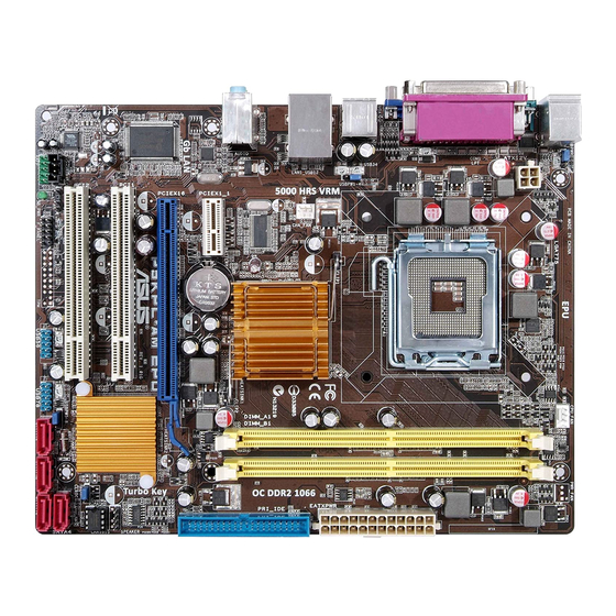
Page 16: Motherboard Layout
1.5.3 Motherboard layout 1.5.4 Layout contents Connectors/Jumpers/Slots Page Connectors/Jumpers/Slots Page ATX power connectors (24-pin EATXPWR, 4-pin 1-28 System panel connector (10-1 pin 1-29 ATX12V) F_PANEL) LGA775 CPU socket USB connectors (10-1 pin USB56 and 1-26 USB78) DDR2 DIMM slots 1-12 Onboard LED (SB_PWR) CPU fan connector (4-pin CPU_FAN) 1-25... -
Page 17: Central Processing Unit (Cpu)
Contact your retailer immediately if the PnP cap is missing, or if you see any damage to the PnP cap/socket contacts/motherboard components. ASUS will shoulder the cost of repair only if the damage is shipment/transit-related. • Keep the cap after installing the motherboard. ASUS will process Return Merchandise Authorization (RMA) requests only if the motherboard comes with the cap on the LGA775 socket. - Page 18 Press the load lever with your thumb Retention tab (A), then move it to the left (B) until it is released from the retention tab. To prevent damage to the socket pins, do not remove the PnP cap unless you are installing a CPU. Load lever Lift the load lever in the direction of the PnP cap...
- Page 19 To prevent contaminating the paste, DO NOT spread the paste with your finger directly. Close the load plate (A), then push the load lever (B) until it snaps into the retention tab. ASUS P5KPL-AM/PS...
-
Page 20: Installing The Cpu Heatsink And Fan
1.6.2 Installing the CPU heatsink and fan The Intel LGA775 processor requires a specially designed heatsink and fan assembly to ® ensure optimum thermal condition and performance. • When you buy a boxed Intel processor, the package includes the CPU fan and ®... -
Page 21: Uninstalling The Cpu Heatsink And Fan
To uninstall the CPU heatsink and fan: Disconnect the CPU fan cable from the connector on the motherboard. Rotate each fastener counterclockwise. Pull up two fasteners at a time in a diagonal sequence to disengage the heatsink and fan assembly from the motherboard. ASUS P5KPL-AM/PS 1-11... -
Page 22: System Memory
Carefully remove the heatsink and fan assembly from the motherboard. Rotate each fastener clockwise to ensure correct orientation when reinstalling. System memory 1.7.1 Overview The motherboard comes with two Double Data Rate 2 (DDR2) Dual Inline Memory Modules (DIMM) sockets. The figure illustrates the location of the DDR2 DIMM sockets: Channel Sockets Channel A... -
Page 23: Memory Configurations
Vista x 64 Edition ® ® • Some old-version DDR2-800 DIMMs may not match Intel On-Die-Termination (ODT) ® requirement and will automatically downgrade to run at DDR-667. If this heppens, contact your memory vendor to check the ODT value. ASUS P5KPL-AM/PS 1-13... - Page 24 P5KPL-AM/PS Motherboard Qualified Vendors List DDR2-667 MHz capability DIMM support Size Vendor Model Brank Side(s) Part No. 256MB Kingston KVR667D2N5/256 Elpida E2508AB-6E-E • • 256MB Kingston KVR667D2N5/256 Kingston D3216TLSAKL3U • • 256MB Kingston KVR667D2N5/256 Infineon HYB18T256800AF3SW65 33154 • • 512MB Kingston KVR667D2N5/512 Kingston...
- Page 25 Century CENTURY 512MB Hynix HY5PS12821AFP-Y5 • • Century CENTURY 1G Hynix HY5PS12821AFP-Y5 • • Century CENTURY 1G Nanya NT5TU64M8AE-3C • • 512MB KINGBOX 512MB 667MHz KINGBOX EPD264082200-4 • • KINGBOX DDRII 1G 667MHz KINGBOX EPD264082200-4 • • ASUS P5KPL-AM/PS 1-15...
- Page 26 DDR2-800 MHz capability DIMM support Size Vendor Model Brand Side(s) Part No. 512MB HYMP564U64AP8-S6 AA Hynix HY5PS12821AFP-S6 • • 512MB HYMP564U64BP8-S5 AB Hynix HY5PS12821BFP-S5 • • 512MB HYMP564U64CP8-S5 AB Hynix HY5PS12821CFP-S5 • • HYMP512U64AP8-S6 AA Hynix HY5PS12821AFP-S6 • • HYMP512U64BP8-S5 AB Hynix HY5PS12821BFP-S5 •...
- Page 27 • A*: Supports one module inserted into any slot as Single-channel memory configuration. • B*: Supports one pair of modules inserted into both the yellow slots as one pair of Dual-channel memory configuration. Visit the ASUS website at www.asus.com for the latest QVL. ASUS P5KPL-AM/PS 1-17...
-
Page 28: Installing A Dimm
1.7.3 Installing a DIMM Unplug the power supply before adding or removing DIMMs or other system components. Failure to do so can cause severe damage to both the motherboard and the components. To install a DIMM: DDR2 DIMM notch Press the retaining clips outward to unlock a DDR2 DIMM socket. -
Page 29: Expansion Slots
This motherboard supports PCI Express x1 network cards, SCSI cards, and other cards that comply with the PCI Express specifications. 1.8.5 PCI Express x16 slot This motherboard supports a PCI Express x16 graphics card that complies with the PCI Express specifications. ASUS P5KPL-AM/PS 1-19... -
Page 30: Jumpers
Jumpers Clear RTC RAM (3-pin CLRTC) This jumper allows you to clear the Real Time Clock (RTC) RAM in CMOS. You can clear the CMOS memory of date, time, and system setup parameters by erasing the CMOS RTC RAM data. The onboard button cell battery powers the RAM data in CMOS, which include system setup information such as system passwords. -
Page 31: Connectors
Microphone port (pink). This port connects a microphone. In a 6-channel configuration, the function of this port becomes Center/Bass. Refer to the audio configuration table on the next page for the function of the audio ports in 2, 4, or 6-channel configuration. ASUS P5KPL-AM/PS 1-21... -
Page 32: Internal Connectors
Audio 2, 4, or 6-channel configuration Port Headset 4-channel 6-channel 2-channel Light Blue Line In Rear Speaker Out Rear Speaker Out Lime Line Out Front Speaker Out Front Speaker Out Pink Mic In Mic In Bass/Center USB 2.0 ports 1 and 2. These two 4-pin Universal Serial Bus (USB) ports are available for connecting USB 2.0 devices. - Page 33 The Serial ATA 3Gb/s is backward compatible with Serial ATA 1.5Gb/s specification. The data transfer rate of the Serial ATA 3Gb/s is faster than the standard parallel ATA with 133 MB/s (Ultra DMA133). Install the Windows XP Service Pack 1 before using Serial ATA. ® ASUS P5KPL-AM/PS 1-23...
- Page 34 IDE connector (40-1 pin PRI_IDE) The onboard IDE connector is for the Ultra DMA 100/66/33 signal cable. There are three connectors on each Ultra DMA 100/66/33 signal cable: blue, black, and gray. Connect the blue connector to the motherboard’s IDE connector, then select one of the following modes to configure your device.
- Page 35 Do not forget to connect the fan cable to the fan connector. Insufficient air flow inside the system may damage the motherboard components. This is not a jumper! Do not place a jumper cap on the fan connector! ASUS P5KPL-AM/PS 1-25...
- Page 36 USB connectors (10-1 pin USB56, USB78) These connectors are for USB 2.0 ports. Connect the USB module cable to any of these connectors, then install the module to a slot opening at the back of the system chassis. These USB connectors comply with USB 2.0 specification that supports up to 480 Mbps connection speed.
-
Page 37: Front Panel Audio Connector
[HD Audio]. See section 2.4.4 Chipset for details. Speaker connector (4- pin SPEAKER) This 4-pin connector is for the chassis-mounted system warning speaker. The speaker allows you to hear system beeps and warnings. ASUS P5KPL-AM/PS 1-27... - Page 38 ATX power connectors (24-pin EATXPWR, 4-pin ATX12V) These connectors are for ATX power supply plugs. The power supply plugs are designed to fit these connectors in only one orientation. Find the proper orientation and push down firmly until the connectors completely fit. •...
-
Page 39: System Panel Connector
Pressing the power switch for more than four seconds while the system is ON turns the system OFF. • Reset button (2-pin RESET) This 2-pin connector is for the chassis-mounted reset button for system reboot without turning off the system power. ASUS P5KPL-AM/PS 1-29... -
Page 40: Software Support
The contents of the Support DVD are subject to change at any time without notice. Visit the ASUS website at www.asus.com for updates. To run the Support DVD Place the Support DVD to the optical drive. -
Page 41: Chapter 2: Bios Information
Save a copy of the original motherboard BIOS file to a floppy disk or a USB flash disk in case you need to restore the BIOS in the future. Copy the original motherboard BIOS using the ASUS Update or AFUDOS utilities. 2.1.1 Creating a bootable floppy disk Create a bootable floppy disk using a different computer. -
Page 42: Asus Update Utility
2.1.2 ASUS Update utility The ASUS Update is a utility that allows you to manage, save, and update the motherboard BIOS in Windows environment. ® • ASUS Update requires an Internet connection either through a network or an Internet Service Provider (ISP). -
Page 43: Asus Ez Flash 2 Utility
2.1.3 ASUS EZ Flash 2 utility The ASUS EZ Flash 2 feature allows you to update the BIOS without having to use a bootable floppy disk or an OS-based utility. Before using this utility, download the latest BIOS file from the ASUS website at www.asus. -
Page 44: Afudos Utility
• Obtain the AFUDOS utility (afudos.exe) from the bundled support DVD and the latest BIOS file from the ASUS website at www.asus.com. • We recommend that you write the BIOS filename on a piece of paper. You will need to key in the exact BIOS filename at the DOS prompt later. -
Page 45: Asus Crashfree Bios 3 Utility
2.1.5 ASUS CrashFree BIOS 3 utility The ASUS CrashFree BIOS 3 is an auto recovery tool that allows you to restore the BIOS file when it fails or gets corrupted during the updating process. You can update a corrupted BIOS file using the motherboard support DVD, a floppy disk, or a USB flash disk that contains the updated BIOS file. -
Page 46: Bios Setup Program
• The BIOS setup screens shown in this section are for reference purposes only, and may not exactly match what you see on your screen. • Visit the ASUS website at www.asus.com to download the latest BIOS file for this motherboard. -
Page 47: Bios Menu Screen
2.2.1 BIOS menu screen Menu items Menu bar General help Configuration fields BIOS SETUP UTILITY Main Advanced Power Boot Tools Exit Use [ENTER], [TAB] System Time [00:38:56] or [SHIFT-TAB] to System Date [Mon 05/12/2008] select a field. Legacy Diskette A [1.44M, 3.5 in.] Use [+] or [-] to configure system Time. -
Page 48: Menu Items
<Page Up> /<Page Scroll bar Down> keys to display the other items on the screen. 2.2.9 General help At the top right corner of the menu screen is a brief description of the selected item. ASUS P5KPL-AM/PS... -
Page 49: Main Menu
Main menu When you enter the BIOS Setup program, the Main menu screen appears, giving you an overview of the basic system information. Refer to section “2.2.1 BIOS menu screen” for information on the menu screen items and how to navigate through them. BIOS SETUP UTILITY Main Advanced... -
Page 50: Storage Configuration
PATA devices and two SATA mode. [Enhanced] - Sets all SATA devices to operate in SATA mode. Enhanced Mode Support On [S-ATA] Sets Serial ATA, Parallel ATA or both as native mode. Configuration options: [S-ATA] [S-ATA+P-ATA] [P-ATA] 2-10 ASUS P5KPL-AM/PS... -
Page 51: System Information
IDE Detect Time Out (Sec) [35] Selects the time out value for detecting ATA/ATAPI devices. Configuration options: [0] [5] [10] [15] [20] [25] [30] [35] 2.3.6 System Information This menu gives you an overview of the general system specifications. The BIOS automatically detects the items in this menu. - Page 52 Manually set ICH Chipset Voltage or set to Auto for safe mode. Configuration options: [Auto] [1.5V] [1.6V] Vcore Over Voltage [Auto] Manually set Vcore Voltage or set to Auto for safe mode. Configuration options: [Auto] [+50mv] [+100mv] [+150mv] 2-12 ASUS P5KPL-AM/PS...
-
Page 53: Usb Configuration
2.4.2 USB Configuration The items in this menu allows you to change the USB-related features. Select an item then press <Enter> to display the configuration options. The Module Version and USB Devices Enabled items show the auto-detected values. If no USB device is detected, the item shows None. -
Page 54: Chipset
Allows you to select the amout of system memory used by the Interanal graphics device. Configuration options: [Disabled] [Enabled, 1MB] [Enabled, 8MB] PEG Port Configuration PEG Force x1 [Disabled] Allows you to enable or disable the PEG Forec x 1. Configuration options: [Enabled] [Disabled] 2-14 ASUS P5KPL-AM/PS... -
Page 55: Onboard Devices Configuration
Video Function Configuration DVMT Mode Select [DVMT Mode] Allows you to select the DVMT mode. Configuration options: [Fixed Mode] [DVMT Mode] DVMT/FIXED Memory [256MB] Allows you to select the amount of the DVMT/FIXED memory. Configuration options: [128MB] [256MB] [Maximum DVMT] South Bridge Configuration Audio Controller [Azalia] Allows you to set the audio controller. -
Page 56: Pci Pnp
Management (APM). Select an item then press <Enter> to display the configuration options. Select the ACPI state Suspend Mode [Auto] used for System ACPI 2.0 Support [Disabled] Suspend. ACPI APIC Support [Enabled] APM Configuration Hardware Monitor Select Screen Select Item Change Option General Help Save and Exit Exit 2-16 ASUS P5KPL-AM/PS... -
Page 57: Apm Configuration
2.5.1 Suspend Mode [Auto] Allows you to select the Advanced Configuration and Power Interface (ACPI) state to be used for system suspend. Configuration options: [S1 (POS) Only] [S3 Only] [Auto] 2.5.2 ACPI 2.0 Support [Disabled] Allows you to add more tables for Advanced Configuration and Power Interface (ACPI) 2.0 specifications. -
Page 58: Hardware Monitor
Exit Specifies the Boot Boot Settings Device Priority sequence. Boot Device Priority A virtual floppy disk drive (Floppy Drive B:) Boot Settings Configuration may appear when you set Security the CD-ROM drive as the first boot device. 2-18 ASUS P5KPL-AM/PS... -
Page 59: Boot Device Priority
This allows you to enable or disable the full screen logo display feature. Configuration options: [Disabled] [Enabled] Set this item to [Enabled] to use the ASUS MyLogo2™ feature. Add On ROM Display Mode [Force BIOS] Sets the display mode for option ROM. Configuration options: [Force BIOS] [Keep Current] Bootup Num-Lock [On] Allows you to select the power-on state for the NumLock. -
Page 60: Security
To set a User Password: Select the Change User Password item and press <Enter>. From the password box, type a password composed of up to six letters and/or numbers, then press <Enter>. Confirm the password when prompted. 2-20 ASUS P5KPL-AM/PS... -
Page 61: Tools Menu
AI NET2 2.7.1 ASUS EZ Flash 2 Allows you to run ASUS EZ Flash 2. When you press <Enter>, a confirmation message appears. Use the left/right arrow key to select between [Yes] or [No], then press <Enter> to confirm your choice. -
Page 62: Exit Menu
When you select this option or if you press <F5>, a confirmation window appears. Select OK to load default values. Select Exit & Save Changes or make other changes before saving the values to the non-volatile RAM. 2-22 ASUS P5KPL-AM/PS...