IBM NetVista A40 User Manual
User guide for netvista 6058, 6059, 6269, 6568, 6569, 6578, 6579, 6648, and 6649 systems (english)
Hide thumbs
Also See for NetVista A40:
- Benutzerhandbuch (164 pages) ,
- User manual (160 pages) ,
- Guía del usuario (158 pages)

Related Manuals for IBM NetVista A40


Summary of Contents for IBM NetVista A40
- Page 1 ™ IBM NetVista User Guide A20 Type 6269 A40 Types 6568, 6578, 6648 A40p Types 6569, 6579, 6649...
- Page 3 ™ IBM NetVista User Guide A20 Type 6269 A40 Types 6568, 6578, 6648 A40p Types 6569, 6579, 6649...
- Page 4 Note Before using this information and the product it supports, be sure to read “Safety information” on page iii and “Appendix E. Notices and trademarks” on page 117. Third Edition (December 2000) © Copyright International Business Machines Corporation 2000. All rights reserved. US Government Users Restricted Rights –...
-
Page 5: Safety Information
Safety information DANGER Electrical current from power, telephone, and communication cables is hazardous. To avoid a shock hazard: v Do not connect or disconnect any cables or perform installation, maintenance, or reconfiguration of this product during an electrical storm. v Connect all power cords to a properly wired and grounded electrical outlet. - Page 6 v Branchez sur des socles de prise de courant correctement câblés tout équipement connecté à ce produit. v Lorsque cela est possible, n’utilisez qu’une seule main pour connecter ou déconnecter les câbles d’interface.; v Ne mettez jamais un équipement sous tension en cas d’incendie ou d’inondation, ou en présence de dommages matériels.
-
Page 7: Lithium Battery Notice
Lithium battery notice CAUTION: Danger of explosion if battery is incorrectly replaced. When replacing the battery, use only IBM Part Number 33F8354 or an equivalent type battery recommended by the manufacturer. The battery contains lithium and can explode if not properly used, handled, or disposed Do not: v Throw or immerse into water v Heat to more than 100°C (212°F) -
Page 8: Laser Compliance Statement
v Do not use the telephone to report a gas leak in the vicinity of the leak. Consignes de sécurité relatives au modem Lors de l’utilisation de votre matériel téléphonique, il est important de respecter les consignes ci-après afin de réduire les risques d’incendie, d’électrocution et d’autres blessures : v N’installez jamais de cordons téléphoniques durant un orage. - Page 9 DANGER Laser radiation when open. Do not stare into the beam, do not view directly with optical instruments, and avoid direct exposure to the beam. DANGER: Certains modèles d’ordinateurs personnels sont équipés d’origine d’une unité de CD-ROM ou de DVD-ROM. Mais ces unités sont également vendues séparément en tant qu’options.
- Page 10 viii User Guide...
-
Page 11: About This Book
About this book ® ™ This book will help you become familiar with your IBM NetVista computer and its features. It describes how to set up, operate, maintain, and install options in your computer. In the unlikely event you experience problems, you will find helpful troubleshooting information and instructions for obtaining service in this book. - Page 12 User Guide...
-
Page 13: Table Of Contents
Contents Safety information . . iii Lithium battery notice . Modem safety information Laser compliance statement . . vi About this book . ix Related information . . ix Chapter 1. IBM NetVista computer overview . Identifying your computer . Small form factor desktop models . - Page 14 LANClient Control Manager (LCCM). . 22 System Migration Assistant (SMA). . 23 Desktop Management Interface . . 23 Using security features . 23 Anti-intrusion features. . 23 Component protection . . 23 Asset ID capability . . 24 IBM security solutions . .
- Page 15 Setting power-management features . . 40 Chapter 5. Installing options . . 43 Handling static-sensitive devices . . 43 Available options . 43 Tools required . 44 Removing the cover . 45 Locating components—small form factor desktop model . . 46 Locating components—desktop model .
- Page 16 Monitor problems . . 86 Keyboard, mouse, or pointing device problems . 89 Memory problems . . 90 Option problems . 91 Parallel-port problems . . 92 Serial-port problems . 92 Printer problems. . 93 Application problems . . 93 Universal Serial Bus (USB) problems .
- Page 17 Electronic emissions notices . 119 Class B notices . . 119 Federal Communications Commission (FCC) statement . . 119 Class A notices . . 121 Federal Communications Commission (FCC) statement . . 121 Industry Canada Class A emission compliance statement . .
- Page 18 User Guide...
-
Page 19: Chapter 1. Ibm Netvista Computer Overview
Chapter 1. IBM NetVista computer overview Thank you for selecting an IBM NetVista computer. Your computer incorporates many of the latest advances in computer technology and can be upgraded as your needs change. This section provides an overview of the computer features, preinstalled software, and specifications. -
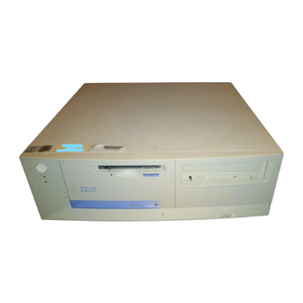
Page 20: Small Form Factor Desktop Models
Small form factor desktop models Small form factor desktop models have a diskette drive and a hard disk drive. Some models have a slimline CD-ROM drive. The power button is located on the right-hand side of the computer as you are facing it. User Guide... -
Page 21: Desktop Models
Desktop models Desktop models come with a diskette drive and a hard disk drive. Some models come with a CD-ROM drive. The power button is located on the left-hand side of the computer as you are facing it. Chapter 1. IBM NetVista computer overview... -
Page 22: Features
Features Not all models come with all features summarized here. Microprocessor ® ™ Intel Pentium III microprocessor with 256 KB of internal L2 cache memory ™ or an Intel Celeron microprocessor with 128 KB of internal L2 cache memory. Memory v Support for: –... - Page 23 Input/output features v 25-pin, ECP/EPP parallel port v One or two 9-pin serial ports v Two 4-pin, USB ports v PS/2 mouse port v PS/2 keyboard port v 15-pin monitor port v Three audio connectors (line/headphone out, line in, and microphone) v Joystick/MIDI connector (some models) Expansion v Small form factor desktop models...
- Page 24 Operating systems (supported) ® v Microsoft ® Windows 2000 Professional ® v Microsoft Windows NT Workstation Version 4.0 with Service Pack 6 v Microsoft Windows 98 SE v Microsoft Windows Millennium (Me) v Novell NetWare Versions 3.2, 4.11, 5.0 Operating systems (tested for compatibility) v Microsoft Windows 95 v DOS 2000 v SCO OpenServer 5.0.2 and later...
-
Page 25: Chapter 2. Setting Up Your Computer
Chapter 2. Setting up your computer This section provides information for connecting cables to your computer and turning on the power. You will need the following: v Computer v Computer power cord v Keyboard v Mouse v Monitor (sold separately with signal cable and power cord) If you are missing an item, contact your place of purchase. - Page 26 1 Mouse connector 8 Audio input connector 2 USB connector 2 9 Microphone connector 3 Parallel connector 10 Monitor connector 4 Serial connector 2 11 Serial connector 1 5 Power cord connector 12 USB connector 1 6 Ethernet connector 13 Keyboard connector 7 Audio output connector Note: The connectors on the rear of the computer have color-coded icons.
- Page 27 Power cord Microphone connector Mouse connector Audio input connector USB connector 2 Audio output connector USB connector 1 Monitor connector Serial connector 2 Serial connector 1 Parallel connector Keyboard connector joystick/MIDI Note: The connectors on the rear of the computer have color-coded icons. Icons will help you to determine where to connect the proper cables on your computer.
- Page 28 1. If your computer is the desktop model, check the position of the voltage-selection switch. Use a ballpoint pen to slide the switch, if necessary. v If the voltage supply range is 90–137 V ac, set the voltage switch to 115 v If the voltage supply range is 180–265 V ac, set the voltage switch to 230 Voltage Switch 2.
-
Page 29: Turn On Power
Turn on power Turn on the monitor and other external devices first, and then turn on the computer. See the following illustrations for the location of the power switches for the monitor and the computer. Chapter 2. Setting up your computer... -
Page 30: Finish The Installation
You see a logo screen while the computer performs a short self-test. When the task completes successfully, the logo screen disappears, the BIOS is loaded, and the software is loaded (in models with preinstalled software). Note: If you suspect a problem, see “Chapter 6. Troubleshooting” on page 71. Finish the installation Note the identification numbers (serial and model/type) on the front of the computer and record this information in “Appendix D. -
Page 31: Arranging Your Workspace
preinstalled at http://www.ibm.com/pc/support/ on the World Wide Web. Installation instructions are provided in README files with the device driver files. Arranging your workspace To get the most from your computer, arrange both the equipment you use and your work area to suit your needs and the kind of work you do. Your comfort is of foremost importance, but light sources, air circulation, and the location of electrical outlets also can affect the way you arrange your workspace. -
Page 32: Glare And Lighting
Glare and lighting Position the monitor to minimize glare and reflections from overhead lights, windows, and other light sources. Even reflected light from shiny surfaces can cause annoying reflections on your monitor screen. Place the monitor at right angles to windows and other light sources, when possible. Reduce overhead lighting, if necessary, by turning off lights or using lower wattage bulbs. -
Page 33: Chapter 3. Operating And Caring For Your Computer
Chapter 3. Operating and caring for your computer This chapter provides information to help you in the day-to-day use and care of your computer. Starting your computer See “Turn on power” on page 11 for an illustration indicating the location of the power buttons on your computer monitor. -
Page 34: Video Device Drivers
Video device drivers To take full advantage of the graphics adapter in your computer, some operating systems and application programs require custom software, known as video device drivers. These device drivers provide support for greater speed, higher resolution, more available colors, and flicker-free images. Device drivers for the integrated graphics subsystem and a README file with instructions for installing the device drivers are preinstalled on models with preinstalled operating systems. -
Page 35: Using Audio Features
Using audio features Your computer comes with an integrated audio controller that supports Sound Blaster applications and is compatible with the Microsoft Windows Sound System. Some models also come with a single internal speaker and three audio connectors. The audio controller provides you with the ability to record and play sound and music and to enjoy sound with multimedia applications. -
Page 36: Using Diskettes
Using diskettes You can use 3.5-inch diskettes in the diskette drive of your computer. The information that follows will help you use 3.5-inch diskettes. Handling and storing diskettes Inside the protective diskette case is a flexible disk with a magnetic coating. This disk can be damaged by heat, dust, a magnetic field, or even a fingerprint. -
Page 37: Handling A Cd
– High temperature – High humidity – Excessive dust – Excessive vibration or sudden shock – An inclined surface – Direct sunlight v Do not insert any object other than a CD into the drive. v Before moving the computer, remove the CD from the drive. Handling a CD When handling a CD, follow these guidelines: v Hold the CD by its edges. -
Page 38: Using The Ibm Scrollpoint Ii Mouse
Note: If the tray does not slide out of the drive when you press the Eject/Load button, insert the pointed end of a large paper clip into the emergency-eject hole located on the front of the CD-ROM drive. Using the IBM ScrollPoint II mouse ®... -
Page 39: Updating System Programs
Updating system programs System programs are the basic layer of software built into your computer. They include the power-on self-test (POST), the basic input/output system (BIOS) code, and the Configuration/Setup Utility program. POST is a set of tests and procedures that is performed each time you turn on your computer. BIOS is a layer of software that translates instructions from other layers of software into electrical signals that the computer hardware can understand. -
Page 40: Wake On Lan
Wake on LAN The Wake on LAN feature requires a Wake on LAN network adapter. A network administrator can use this feature to turn on your computer from a remote location. When Wake on LAN is used in conjunction with network management software (provided on the Software Selections CD that comes with your computer), many types of functions, such as data transfers, software updates, and POST or BIOS updates to your computer can be initiated... -
Page 41: System Migration Assistant (Sma)
System Migration Assistant (SMA) System Migration Assistant (SMA) delivers wizard-like functionality to help administrators remotely transfer configurations, profile settings, printer drivers, and files from an IBM or non-IBM PC to supported IBM systems. If you have purchased an IBM computer, SMA is available for downloading at no additional charge (Internet access fees excepted). -
Page 42: Asset Id Capability
about component registration, see the IBM support page at http://www.ibm.com/pc/us/desktop/assetid/ on the World Wide Web. Asset ID capability IBM provides the basis for Asset ID support in some models. Asset ID provides the capability to access information that is stored in an EEPROM module on the system board, using a radio-frequency-enabled portable scanner. -
Page 43: Data Protection
Data protection You can lose data from the hard disk for a variety of reasons. Security violations, viruses, or hard disk drive failure can all contribute to the destruction of data files. To protect against the loss of valuable information, IBM has incorporated many data-saving features within your computer. -
Page 44: Shutting Down
Note: If you have a USB keyboard, it will function even if a password has been placed on the computer. Some operating systems have a keyboard and mouse lock-up feature. Check the documentation that comes with your operating system for more information. -
Page 45: Computer And Keyboard
Computer and keyboard Use only mild cleaning solutions and a damp cloth to clean the painted surfaces of the computer. Monitor screen Do not use abrasive cleaners when cleaning the surface of the monitor screen. The screen surface is easily scratched, so avoid touching it with pens, pencil points, and erasers. -
Page 46: Moving Your Computer
Moving your computer Take the following precautions before moving your computer. 1. Back up all files and data from the hard disk. Operating systems can vary in the way they perform backup procedures. Refer to your operating system documentation for information about software backup. -
Page 47: Chapter 4. Using The Configuration/Setup Utility Program
Chapter 4. Using the Configuration/Setup Utility program The Configuration/Setup Utility program is stored in the electrically erasable programmable read-only memory (EEPROM) of your computer. You can use the Configuration/Setup Utility program to view and change the configuration settings of your computer, regardless of which operating system you are using. However, the settings you select in your operating system might override any similar settings in the Configuration/Setup Utility program. -
Page 48: Viewing And Changing Settings
Viewing and changing settings The menu on your computer might look slightly different from the menu shown here, but it will operate the same way. Configuration/Setup Utility Select Option: v System Summary v Product Data v Devices and I/O Ports v Start Options v Date and Time v System Security... -
Page 49: Exiting From The Configuration/Setup Utility Program
Keys Function Press this key to exit from a menu after viewing or making changes to the settings in the menu. Use this key in some menus to increase the numerical value of a setting. − Use this key (the minus or hyphen key) in some menus to decrease the numerical value of a setting. -
Page 50: Using Security Profiles By Device
v The security EEPROM will be protected from unauthorized access because it locks after your computer is turned on and the system programs have completed their startup routine. Once it is locked, the security EEPROM cannot be read from or written to by any software application or system software until the computer is turned off and back on again. -
Page 51: Setting Remote Administration
v Diskette Write Protect: When the feature is set to Enable, all diskettes are treated as if write-protected. Setting Security Profile by Device also enables you to control which devices require a password before they start up. There are three classes of these devices: v Removable media, such as diskette drives and CD-ROM drives v Hard disk drives... -
Page 52: Using Passwords
To set Remote Administration, follow these steps: 1. Start the Configuration/Setup Utility program. See “Starting and using the Configuration/Setup Utility program” on page 29. 2. Select System Security and press Enter. 3. Select Remote Administration and press Enter. 4. To enable Update Remote Administration, select Enabled. To disable, select Disabled. -
Page 53: Setting, Changing, And Deleting A Power-On Password
when you turn on the computer. The operating system will start but you must type the password before you can log on or access applications. In the password prompt Dual mode, the startup behavior of the Dual computer depends on whether the computer is started from the computer power switch or by an unattended method, such as remotely over a LAN. -
Page 54: Using An Administrator Password
Using an administrator password Setting an administrator password deters unauthorized persons from changing configuration settings. If you are responsible for maintaining the settings of several computers, you might want to set an administrator password. After you set an administrator password, a password prompt appears each time you try to access the Configuration/Setup Utility program. -
Page 55: Erasing A Lost Or Forgotten Password (Clearing Cmos)
Erasing a lost or forgotten password (clearing CMOS) This section applies to lost or forgotten passwords that are not protected by Enhanc ed Security. For information about lost or forgotten passwords that are protected by Enhanced Security, see “Using Enhanced Security” on page 31. To erase a forgotten password: 1. -
Page 56: Enabling The Pentium Iii Processor Serial Number Feature
You can clear the IBM Embedded Security Chip by selecting Clear IBM Security Chip and pressing Enter. This will delete all IBM Embedded Security Chip passwords and encryption values and disable the IBM Embedded Security Chip feature. Enabling the Pentium III processor serial number feature The Pentium III microprocessor features a processor serial number feature. -
Page 57: Enabling The Error Startup Sequence
To view or change the primary or automatic power on startup sequence: 1. Start the Configuration/Setup Utility program (see “Starting and using the Configuration/Setup Utility program” on page 29. 2. Select Start Options and press Enter. 3. Select Startup Sequence and press Enter. 4. -
Page 58: Acpi Standby Mode
ACPI Standby Mode Some models might allow you to select the power level to which the computer will go when entering standby mode. These models allow you to select standby mode S1 or S3. When the computer enters S1 mode, power is maintained to all devices, but microprocessor activity is halted. - Page 59 – Off: In this mode, the monitor power is turned off. To restore power to the monitor, you must press the monitor power switch. On some monitors, you might have to press the power switch twice. If Off is selected, you must specify the Time to Display ’Off.’ You can select 5 minutes to 1 hour.
- Page 60 v PCI Wake Up: If this setting is enabled, your computer turns on in response to wake up requests from PCI devices that support this feature. To set automatic power-on features, follow these steps: 1. Start the Configuration/Setup Utility program (see “Starting and using the Configuration/Setup Utility program”...
-
Page 61: Chapter 5. Installing Options
Chapter 5. Installing options You can expand the capabilities of your computer by adding memory, drives, or adapters. When adding an option, use these instructions along with the instructions that come with the option. Important: Before you install any option, see the safety notices in the Quick Reference and read the “Safety information”... -
Page 62: Tools Required
– Hard disk – Diskette drives and other removable media drives For the latest information about available options, see the following World Wide Web pages: v http://www.ibm.com/pc/us/options/ v http://www.ibm.com/pc/support/ You can also obtain information by calling the following telephone numbers: v Within the United States, call 1-800-IBM-2YOU (1-800-426-2968), your IBM reseller, or IBM marketing representative. -
Page 63: Removing The Cover
Removing the cover Important: Read “Safety information” on page iii and “Handling static-sensitive devices” on page 43 before removing the cover. To remove the cover: 1. Shut down your operating system, remove any media (diskettes, CDs, or tapes) from the drives, and turn off all attached devices and the computer. 2. -
Page 64: Locating Components-Small Form Factor Desktop Model
Locating components—small form factor desktop model The following illustration will help you locate the various components in your computer. 1 Fan 5 Slimline CD-ROM drive (some models) 2 Microprocessor 6 System board 3 DIMM 7 Riser card housing 4 Diskette drive User Guide... -
Page 65: Locating Components-Desktop Model
Locating components—desktop model The following illustration will help you locate the various components in your computer. 1 CD-ROM drive 6 System board 2 Empty drive bay 7 Microprocessor 3 Hard disk drive 8 AGP adapter (some models) 4 Diskette drive 9 PCI slot 5 DIMM Chapter 5. -
Page 66: Installing Options On The System Board And Riser Card (Some Models)
Installing options on the system board and riser card (some models) This section provides instructions for installing options, such as system memory and adapters, on the system board and the riser card (some models). Accessing the system board To access the system board, you must remove the computer cover. For information on removing the computer cover, see “Removing the cover”... -
Page 67: Components Of The A40 And A40P System Board
Components of the A40 and A40p system board If your computer is a type A40 or A40p, see the following illustration for the location of parts on the system board. Note: An illustration of the system board and additional information is provided on a label located on the inside of the computer chassis. -
Page 68: Components Of The Riser Card For Small Form Factor Desktop Models
Components of the riser card for small form factor desktop models The following illustration shows the location of PCI connectors on the riser card for small form factor desktop model computers. 1 PCI slot 1 2 Ethernet disable jumper 3 PCI slot 2 User Guide... -
Page 69: Components Of The A20 System Board
Components of the A20 system board If your computer is a type A20 computer, see the following information for the location of parts on the system board. Note: An illustration of the system board and additional information is provided on a label located on the inside of the computer chassis. CPU fan connector Clear CMOS/Recovery jumper Microprocessor... - Page 70 Your computer uses dual inline memory modules (DIMMs). The IBM-installed DIMMs that come with your computer are unbuffered, synchronous dynamic random access memory (SDRAM). When installing DIMMs, the following rules apply: v Fill each system memory connector sequentially, starting at DIMM 1. v Use 3.3 V, 133 MHz, unbuffered, SDRAM DIMMs.
-
Page 71: Installing Adapters
Notches What to do next: v Replace the AGP adapter and adapter slot cover latch. v To work with another option, go to the appropriate section. v To complete the installation, go to “Completing the installation” on page 66. Installing adapters This section provides information and instructions for installing and removing adapters. -
Page 72: Installing Adapters - Small Form Factor Desktop Model
Installing adapters — small form factor desktop model To install an adapter in a PCI expansion slot: 1. Remove the cover and all cables. See “Removing the cover” on page 45. 2. Remove the riser card housing and place the housing on its side with the adapter slots facing up. - Page 73 5. Install the adapter and insert the retaining screw. Note: If you are installing a Wake on LAN-supported network adapter, attach the Wake on LAN cable that came with the adapter to the Wake on LAN connector on the system board. Chapter 5.
-
Page 74: Installing Adapters - Desktop Model
6. Replace the riser card housing. 7. Replace the cover and connect the cables (see “Replacing the cover and connecting the cables” on page 66); then continue with “Updating the computer configuration” on page 67. Installing adapters — desktop model To install an adapter in a PCI or AGP expansion slot: 1. - Page 75 2. Remove the adapter slot cover latch and the slot cover for the appropriate expansion slot. 3. Remove the adapter from its static-protective package. 4. Install the adapter into the appropriate slot on the system board. 5. Install the adapter slot cover latch. Chapter 5.
-
Page 76: Installing Internal Drives
Note: If you are installing a Wake on LAN-supported network adapter, attach the Wake on LAN cable that came with the adapter to the Wake on LAN connector on the system board. 6. Replace the cover and connect the cables (see “Replacing the cover and connecting the cables”... -
Page 77: Drive Specifications - Small Form Factor Desktop Model
Drive specifications — small form factor desktop model Your computer comes with the following IBM-installed drives: v A CD-ROM drive in bay 1 (some models) v A 3.5-inch hard disk drive in bay 2 v A 3.5-inch diskette drive in bay 3 Models that do not have drives installed in bay 3 have a static shield and bay panel installed. -
Page 78: Drive Specifications - Desktop Model
Drive specifications — desktop model Your computer comes with the following IBM-installed drives: v A CD-ROM drive in bay 1 (some models). v A 3.5-inch hard disk drive in bay 3. v A 3.5-inch diskette drive in bay 4. Models that do not have drives installed in bays 1 and 2 have a static shield and bay panel installed. -
Page 79: Power And Signal Cables For Internal Drives
Power and signal cables for internal drives Your computer uses cables to connect integrated drive electronics (IDE) drives to the power supply and to the system board. The following cables are provided: v Four-wire power cables connect most drives to the power supply. At the end of these cables are plastic connectors that attach to different drives;... - Page 80 v The drives that are preinstalled in your computer come with power and signal cables attached. If you replace any drives, it is important to remember which cable is attached to which drive. v When you install a drive, ensure that the drive connector at the end of the signal cable is always connected to a drive;...
-
Page 81: Installing Internal Drives In The Desktop Model Computer
Installing internal drives in the desktop model computer To install an internal drive in the desktop model computer: To remove the cover: 1. See “Removing the cover” on page 45. Note: If your computer has a CD-ROM drive, you might need to remove the signal and power cables from the CD-ROM drive. - Page 82 3. Install the drive into the bay. Align the screw holes and insert the two screws. 4. Pivot the drive bay cage back into place. User Guide...
- Page 83 5. If you are installing a drive with removable media, insert a flat–bladed screwdriver into one of the slots on the static shield in the drive bay into which you are installing the drive and gently pry the static shield loose from the drive bay.
-
Page 84: Installing A Security U-Bolt
What to do next v To work with another option, go to the appropriate section. v To complete the installation, go to “Completing the installation”. Installing a security U-bolt To help prevent hardware theft, you can add a security U-bolt and cable to your computer. -
Page 85: Updating The Computer Configuration
3. Position the cover over the chassis and pivot the cover down over the computer until the cover snaps into place. 4. Reconnect the external cables and cords to the computer. See “Connecting computer cables” on page 7. Updating the computer configuration You might need to install device drivers after updating the configuration settings. -
Page 86: Starting The Configuration/Setup Utility Program
to determine if device drivers are required and how to install them. Some device drivers are included in the service partition of your computer. You might need to install device drivers after updating the configuration settings. For more information, see the instructions that come with the option to determine if device drivers are required and how to install them. -
Page 87: Configuring Startup Devices
After you change an option and restart the computer, the following screen might appear. POST Startup Error(s) The following error(s) were detected when the system was started: 162 Configuration Change Has Occurred Select one of the following: Continue Exit Setup Note: Depending on the configuration changes that occurred, the error message you see might be different from the one shown here. - Page 88 User Guide...
-
Page 89: Chapter 6. Troubleshooting
Chapter 6. Troubleshooting This chapter describes diagnostic tools that you can use to identify and correct problems that might arise. This chapter also contains information about option diskettes and how to recover from a BIOS update failure. Computer problems can be caused by hardware, software, or user error (for example, pressing the wrong key). - Page 90 c. Turn on any attached devices; then, turn on the computer. d. Wait the normal amount of time for the first window of your application or the operating system to be displayed. Is either the Windows desktop or the first screen of your application program displayed? No - continue at step 2.
-
Page 91: Power-On Self-Test (Post)
v If the computer was functioning correctly after you installed an option and is now malfunctioning, have the computer serviced. v If the failure occurred immediately after you made a change to the configuration, verify that you selected the correct settings. v If the failure occurred immediately after you installed or removed a new option and you get an error message from the Configuration/Setup Utility program, disconnect the new device. - Page 92 Table 1. POST Error Codes (continued) Code Description Action I/O parity error 2 Go to “IBM Enhanced Diagnostics program” on page 94 and follow the instruction to run diagnostics. Level 1 cache error Have the computer serviced. Fan failure Have the computer serviced. Real time clock failure Have the computer serviced.
- Page 93 Table 1. POST Error Codes (continued) Code Description Action System cover has been removed. Type in the administrator password. If problem persists, have the computer serviced. An inventory violation occurred, Type in the administrator password. such as a hardware component was If the problem persists, have the removed.
- Page 94 Table 1. POST Error Codes (continued) Code Description Action Unsupported diskette drive 1. Go to “IBM Enhanced installed Diagnostics program” on page 94 and if possible run the IBM Enhanced Diagnostics program. 2. If the problem persists, have the computer serviced. Diskette unlocked problem Have the computer serviced.
-
Page 95: Post Beep Codes
Table 1. POST Error Codes (continued) Code Description Action 1962 Boot sequence error 1. Go to “Changing the primary startup sequence” on page 38 and follow the instructions to verify that the startup sequence is configured. 2. If the problem persists, have the computer serviced. -
Page 96: Ethernet Error Messages
Beep code Probable cause 1–3–2 RAM parity test failure 1–4–3 Fail-safe timer test in progress 1–4–4 Software NMI port test in progress 2–1–1 Secondary DMA register test in progress or failure 2–1–2 Primary DMA register test in progress or failure 2–1–3 Primary interrupt mask register test failure 2–1–4... -
Page 97: Dhcp-Related Error Messages
RPL-ROM-ERR: 103 There are multiple Ethernet adapters in the system. Specify the correct serial number in NET.CFG. RPL-ROM-ERR: 104 The Ethernet adapter EEPROM is faulty or not present. RPL-ROM-ERR: 106 The Ethernet adapter is configured for Plug and Play in a non-Plug and Play system. -
Page 98: Device Troubleshooting Charts
M44: Cannot ARP redirected BOOTP server. M6f: System is locked! Press Ctrl+Alt+Del to restart. M90: Cannot initialize controller for multicast. M91: MTFTP canceled by keystroke. M92: MTFTP open timeout. M93: Unknown MTFTP opcode. M94: MTFTP read canceled by keystroke. M95: MTFTP timeout. M96: Cannot ARP MTFTP address. -
Page 99: General Problems
Problem type Go to: CD-ROM drive “CD-ROM drive problems” on page 84 Diskette drive “Diskette drive problems” on page 86 General “General problems” Intermittent “Intermittent problems” on page 82 Keyboard, mouse, or “Keyboard, mouse, or pointing device problems” on page 89 pointing-device Memory “Memory problems”... -
Page 100: Intermittent Problems
Intermittent problems Intermittent problems Action A problem occurs only Verify that: occasionally and is difficult 1. All cables and cords are securely connected to the to detect. rear of the computer and attached devices. 2. When the computer is turned on, the fan grill is not blocked (there is air flow around the grill), and the fans are working. -
Page 101: Audio Problems
Audio problems Symptoms Action No audio in Windows 1. Make sure that headphone and speaker cables are plugged into the correct audio connectors. Plugging a cable into an audio connector disables the built-in speaker. 2. Check the Windows Volume Control program to ensure the volume settings are not set too low or that the mute setting is not enabled. -
Page 102: Cd-Rom Drive Problems
CD-ROM drive problems Symptoms Action An audio or AutoPlay-enabled Make sure you have the Windows AutoPlay feature disc does not automatically enabled. To enable the AutoPlay feature, do the play when inserted into the following: drive 1. From the Windows desktop, double-click My Computer. - Page 103 Symptoms Action A CD does not work. v Verify that the disk is inserted correctly, with its label up. v Make sure that the disk you are using is clean. To remove dust or fingerprints, wipe the CD with a clean, soft cloth from the center to the outside.
-
Page 104: Diskette Drive Problems
Diskette drive problems Diskette drive problems Action Diskette drive in-use light If there is a diskette in the drive, verify that: stays on, or the system 1. The diskette drive is enabled. Use the bypasses the diskette drive. Configuration/Setup Utility program to check this. For more information, see “Chapter 4. - Page 105 Monitor problems Action Wavy, unreadable, rolling, If the monitor self-tests show that the monitor is working distorted, or jittery screen properly, verify that: images. 1. The location of the monitor is appropriate. Magnetic fields around other devices, such as transformers, appliances, fluorescent lights, and other monitors might be causing the problem.
- Page 106 Monitor problems Action The monitor works when Verify that: you turn on the system, but 1. The monitor signal cable is securely connected to the goes blank when you start monitor and the monitor connector on the graphics some application programs. adapter.
-
Page 107: Keyboard, Mouse, Or Pointing Device Problems
Keyboard, mouse, or pointing device problems Keyboard, mouse, or Action pointing- device problems All or some keys on the Verify that: keyboard do not work. 1. The computer and the monitor are turned on. 2. The keyboard cable is securely connected to the keyboard connector on the computer. -
Page 108: Memory Problems
Memory problems Memory problems Action The amount of memory The amount of available memory shown might be displayed is less than the somewhat less than expected because of basic amount of memory input/output system (BIOS) shadowing in random access installed. memory (RAM), video takes 1 MB, and ACPI and USB also can take up to 1 MB. -
Page 109: Option Problems
Option problems Option problems Action An IBM option that was just Verify that: installed does not work. 1. The option is designed for your computer. 2. You followed the installation instructions supplied with the option and in “Chapter 5. Installing options” on page 43. -
Page 110: Parallel-Port Problems
Option problems Action An IBM option that Verify that all option hardware and cable connections are previously worked does not secure. work now. If the option comes with its own test instructions, use those instructions to test the option. If the failing option is a SCSI option, verify that: 1. -
Page 111: Printer Problems
Printer problems Printer problems Action The printer does not work. Verify that: 1. The printer is turned on and is online. 2. The printer signal cable is securely connected to the correct parallel, serial, or USB port on the computer. (See “Connecting computer cables”... -
Page 112: Universal Serial Bus (Usb) Problems
Universal Serial Bus (USB) problems Universal Serial Bus port Action problems The Universal Serial Bus Verify that the USB device is properly installed and ports cannot be accessed. firmly seated. If you cannot correct the problem, have the computer serviced. Software-generated error messages These messages appear if a problem or conflict is detected by the application program, the operating system, or both. - Page 113 5. A new menu opens with the options for viewing system utilities: v Run Diagnostics v Create a diagnostic diskette v System Information v Create a Recovery Repair diskette 6. Select Run Diagnostics to open the IBM Enhanced Diagnostics program to try to track down a problem.
-
Page 114: Other Diagnostic Programs On The Software Selections Cd
The downloaded file is self-extracting and will be copied to the diskette. When the copy completes, you have a startable IBM Enhanced Diagnostics program diskette. To start the IBM Enhanced Diagnostic program using the diskette: 1. Shut down Windows and turn off the computer. 2. -
Page 115: Installing Files From Option Diskettes
8. After the update session completes, remove the diskette from the diskette drive and turn off the computer and monitor. 9. Unplug the power cords from electrical outlets. 10. Remove the cover. See “Removing the cover” on page 45. 11. Remove any adapters that impede access to the BIOS Configuration jumper. - Page 116 4. If necessary, remove any adapters that impede access to the battery. See “Installing adapters — small form factor desktop model” on page 54 or “Installing adapters — desktop model” on page 56 for more information. 5. Remove the old battery. 6.
-
Page 117: Chapter 7. Getting Help, Service, And Information
Chapter 7. Getting help, service, and information If you need help, service, technical assistance, or just want more information about IBM products, you will find a wide variety of sources available from IBM to assist you. This section contains information about where to go for additional information about IBM and IBM products, what to do if you experience a problem with your computer, and whom to call for service should it be necessary. -
Page 118: Getting Help And Service
You can call the IBM Automated Fax System 24 hours a day, 7 days a week. Follow the recorded instructions, and the requested information will be sent to your fax machine. In the U.S. and Canada, to access the IBM Automated Fax System, call 1-800-426-3395. - Page 119 v Replacement or use of non-IBM parts or nonwarranted IBM parts Note: All warranted parts contain a 7-character identification in the format IBM FRU XXXXXXX. v Identification of software problem sources v Configuration of BIOS as part of an installation or upgrade v Changes, modifications, or upgrades to device drivers v Installation and maintenance of network operating systems (NOS) v Installation and maintenance of application programs...
-
Page 120: Other Services
Country Telephone number Austria Österreich 01-24 592 5901 Belgium - Dutch Belgie 02-210 9820 Belgium - French Belgique 02-210 9800 Canada Toronto only 416-383-3344 Canada Canada - all other 1-800-565-3344 Denmark Danmark 35 25 02 91 Finland Suomi 09-22 931 840 France France 02 38 55 74 50... -
Page 121: Purchasing Additional Services
v In Europe, call 44-1475-893638 (Greenock, U.K.). v In Australia and New Zealand, call 61-2-9354-4171. v In all other countries, contact your IBM reseller or IBM marketing representative. IBM Integrated Technology Services offers a broad range of information technology support, implementation, and management services. For more information about these services, refer to the Integrated Technology Services Web site at http://www.ibm.com/services/its/. - Page 122 User Guide...
-
Page 123: Appendix A. Using The Software Selections Cd
Appendix A. Using the Software Selections CD Use the information in this chapter if you want to install software from the IBM Software Selections CD. Important: You must have Microsoft Internet Explorer 4.0 or higher installed to run the IBM Software Selections CD. Features of the Software Selections CD The IBM Software Selections CD contains diagnostic programs and other support software for Windows Millennium, Windows 98, Windows NT Workstation 4.0,... -
Page 124: Starting The Software Selections Cd
Starting the Software Selections CD To use the Software Selections CD, insert the CD into your CD-ROM drive. The Software Selections program starts automatically. If the auto-run feature is disabled in your computer: 1. Click the Windows Start button; then click Run 2. -
Page 125: Appendix B. Specifications
Appendix B. Specifications The following specifications will help you to set up your computer and install options. Specifications — small form factor desktop model Dimensions Height: 87 mm (3.43 in.) Width: 345 mm (13.6 in.) Depth: 360 mm (14.2 in.) Weight: Minimum configuration as shipped: 8.2 kg (18 lb.) Maximum configuration: 8.6 kg (19 lb.) Environment... -
Page 126: Specifications - Desktop Model (A40 And A40P)
Approximately 0.25 cubic meters per minute (9 cubic feet per minute) Acoustical noise-emission values Average sound-pressure levels: At operator position: Idle: 38 dBA Operating: 43 dBA At bystander position–1 meter (3.3 ft.): Idle: 33 dBA Operating: 37 dBA Declared (upper limit) sound power levels: Idle: 4.8 bels Operating: 5.1 bels Note: These levels were measured in controlled acoustical environments according to procedures specified by the American National Standards Institute (ANSI) S12.10 and ISO 7779, and are reported in accordance... -
Page 127: Specifications - Desktop Model (A20)
Input kilovolt-amperes (kVA) (approximately): Minimum configuration as shipped: 0.08 kVA Maximum configuration: 0.30 kVA Note: Power consumption and heat output vary depending on the number and type of optional features installed and the power-management optional features in use. Heat output Approximate heat output in British thermal units (Btu) per hour: Minimum configuration: 240 Btu/hr. - Page 128 Air temperature: System on: 10°to 35°C (50° to 95°F) System off: 10° to 43°C (50° to 110°F) Humidity: System on: 8% to 80% System off: 8% to 80% Maximum altitude: 2134 m (7000 ft.) Electrical input Input voltage: Low range: Minimum: 90 V ac Maximum: 137 V ac Input frequency range: 57-63 Hz Voltage switch setting: 115 V High range: Minimum: 180 V ac Maximum: 265 V ac...
- Page 129 nearby noise sources. The declared sound power levels indicate an upper limit, below which a large number of computers will operate. Appendix B. Specifications...
- Page 130 User Guide...
-
Page 131: Appendix C. Placing The Computer On Its Side
Appendix C. Placing the computer on its side Although your computer was designed to be placed on a desktop, you can place your computer on its side by purchasing a special desktop stand. Small form factor desktop models come with a special desktop stand. Use the instructions in the following sections if you choose to place your computer on its side. - Page 132 2. Place the computer on the stand as illustrated below, with the power button and vent oriented at the top of the computer. User Guide...
-
Page 133: Appendix D. Computer Records
Appendix D. Computer records This appendix contains forms for recording information about your computer, which can be helpful if you decide to install additional hardware, or if you ever need to have your computer serviced. Record and retain the following information. Product name NetVista A20/A40/A40p Model/Type (M/T) _________________________________________________... - Page 134 User Guide...
-
Page 135: Appendix E. Notices And Trademarks
Appendix E. Notices and trademarks This publication was developed for products and services offered in the U.S.A. IBM may not offer the products, services, or features discussed in this document in other countries. Consult your local IBM representative for information on the products and services currently available in your area. Any reference to an IBM product, program, or service is not intended to state or imply that only that IBM product, program, or service may be used. -
Page 136: Processing Date Data
materials at those Web sites are not part of the materials for this IBM product, and use of those Web sites is at your own risk. Processing date data This IBM hardware product and IBM software products that might be packaged with it have been designed, when used in accordance with their associated documentation, to process date data correctly within and between the 20th and 21st centuries, provided all other products (for example, software,... -
Page 137: Electronic Emissions Notices
A modifie ses caractérisques et le rend conforme aux normes de la classe A. Class B notices NetVista A20 Type 6269, NetVista A40 Types 6568, 6578, and 6648, NetVista A40p Types 6569, 6579, and 6649 Federal Communications Commission (FCC) statement Note: This equipment has been tested and found to comply with the limits for a Class B digital device, pursuant to Part 15 of the FCC Rules. - Page 138 v Connect the equipment into an outlet on a circuit different from that to which the receiver is connected. v Consult an IBM authorized dealer or service representative for help. Properly shielded and grounded cables and connectors must be used in order to meet FCC emission limits.
-
Page 139: Class A Notices
This product has been tested and found to comply with the limits for Class B Information Technology Equipment according to CISPR 22/European Standard EN 55022. The limits for Class B equipment were derived for typical residential environments to provide reasonable protection against interference with licensed communication devices. -
Page 140: European Union Emc Directive Conformance Statement
European Union EMC Directive conformance statement This product is in conformity with the protection requirements of EU Council Directive 89/336/EEC on the approximation of the laws of the Member States relating to electromagnetic compatibility. IBM cannot accept responsibility for any failure to satisfy the protection requirements resulting from a nonrecommended modification of the product, including the fitting of non-IBM option cards. -
Page 141: Canadian Department Of Communications Certification Label
the label to the external DAA, if you have one. Place the label in a location that is easily accessible, should you need to provide the label information to the telephone company. 2. The REN is useful to determine the quantity of devices you may connect to your telephone line and still have those devices ring when your number is called. -
Page 142: Étiquette D'homologation Du Ministère Des Communications Du Canada
not prevent degradation of service in some situations. Repairs to certified equipment should be coordinated by a representative designated by the supplier. Any repairs or alterations made by the user to this equipment, or equipment malfunctions, may give the telecommunications company cause to request the user to disconnect the equipment. -
Page 143: Power Cord Notice
Avertissement : L’utilisateur ne doit pas tenter de faire ces raccordements lui-même; il doit avoir recours à un service d’inspection des installations électriques ou à un électricien, selon le cas. AVIS : L’indice d’équivalence de la sonnerie (IES) assigné à chaque dispositif terminal indique le nombre maximal de terminaux qui peuvent être raccordés à... - Page 144 IBM power cord part Used in these countries and regions number 13F9979 Afghanistan, Algeria, Andorra, Angola, Austria, Belgium, Benin, Bulgaria, Burkina Faso, Burundi, Cameroon, Central African Rep., Chad, China (Macau S.A.R.), Czech Republic, Egypt, Finland, France, French Guiana, Germany, Greece, Guinea, Hungary, Iceland, Indonesia, Iran, Ivory Coast, Jordan, Lebanon, Luxembourg, Malagasy, Mali, Martinique, Mauritania, Mauritius, Monaco, Morocco, Mozambique,...
-
Page 145: Index
Index cover (continued) replacing 66 ACPI BIOS IRQ 39 audio connectors 5, 17 controller 17 data protection features 16 Enhanced Security 25 problems 83 SMART hard disk drive 25 subsystem 4 SMART Reaction 25 automatic power-on 41 virus protection 25 Desktop Management Interface 23 device troubleshooting charts 80 cables... - Page 146 expansion (continued) drive bays 5 password erasing 37 lost or forgotten 37 passwords help administrator 5, 25, 36 getting 99 changing 36 deleting 36 setting 36 power-on 5, 25, 34 IBM Enhanced Diagnostics program changing 35 downloading 95 deleting 35 starting from CD 94 setting 35 starting from diskette 96...
- Page 147 startup sequence error 39 Remote Administration 22, 33 primary 38 Remote Program Load 22 system replacing the battery 97 board 47 memory 4 programs 20 security 31 security system board adapter ROM 37 accessing 48 anti-intrusion 23 identifying parts 48 Asset ID 24 system management chassis-intrusion detector 23...
- Page 148 video (continued) monitor settings 16 Wake on LAN 21 User Guide...
- Page 150 Part Number: 19K8332 Printed in the United States of America on recycled paper containing 10% recovered post-consumer fiber.