
Related Manuals for Yamaha YV-1600A


Summary of Contents for Yamaha YV-1600A
- Page 1 CONCERT VIBES YV-3910/3710/3700/2700/2700G/1600A/520 Owner’s Manual Make sure to read the PRECAUTIONS on page 1.
-
Page 2: Special Message Section
This Product should be used only with the components sup- plied or; a cart, rack, or stand that is recommended by Yamaha. If a cart, etc., is used, please observe all safety markings and instructions that accompany the accessory product. - Page 3 PRECAUTIONS Please read the following instructions carefully before using your vibes. Installation Location When Not in Use Use or storage in the following locations may cause • Make sure to turn off the power switch and discon- damage, even when packaged. nect the AC adapter from the outlet.
-
Page 4: Start/Stop Button
NOMENCLATURE : YV-3910/3710/3700/2700/2700G/1600A/520 Accidental Tone Bars Natural Tone Bars Controller Fan Belt Frame End Frame End (Large) (Small) Slide Leg Rail No. 1 Resonators (Natural Tone Side) Slant Shaft Driver Leg (Large) Leg (Small) Resonators (Accidental Pedal Stay Tone Side) Pedal Caster AC Adapter... - Page 5 !0 Rail (3) : Audience Side Rail Clamp Posts !1 Rail (4) : Audience Side e Resonators (Natural Tone Side) Posts YAMAHA Logo !2 Leg (Large) !3 Leg (Small) r Resonators (Accidental Tone Side) !4 AC Adapter !5 Synchro Belt (Fan Belt): 2 pcs.
- Page 6 Rail (3) : Audience Side Rail Clamp Posts !0 Rail (4) : Audience Side Posts e Resonators (Natural Tone Side) YAMAHA Logo !1 Leg (Large) !2 Leg (Small) r Resonators (Accidental Tone Side) !3 AC Adapter !4 Synchro Belt (Fan Belt): 2 pcs.
- Page 7 CONFIRMATION OF PACKING CONTENTS : YV-3910/3710 Dividable Parts and Collapsible Parts (YV-3910/3710 only) The YV-3910’s/YV-3710’s large parts are designed to either divide or collapse. When the instrument is broken down, its compact size makes it easy to transport and storage requires a minimum amount of space. Rails The rails fold in from the center.
- Page 8 ASSEMBLY : YV-3910/3710/3700 For safety, assembly should be performed by at least 2 persons in a location with sufficient space. We recommend to you to assemble the instrument on a soft rug or carpet. Connect the large and the small leg using the reinforcement stay and pedal stay.
- Page 9 ASSEMBLY: YV-3910/3710/3700 YV-3910/3710 : Insert the pedal stay with its notch facing up into the lower joint of the large leg as far as it will go (aligning the notch with the fixing bolt) and tighten the fixing bolt securely. * The hole next to the notch serves as a reference for the correct insertion position.
- Page 10 ASSEMBLY: YV-3910/3710/3700 YV-3700 : Place the large leg, small leg, pedal stay (and reinforcement stay : YV- 3700) so that after assembly each part will be positioned as illustrated. Low Sound Leg (Large) Side Audience Side Reinforcement Stay Leg (Small) High Sound Side Pedal Stay...
- Page 11 Rail (2): With rail clamp and more posts than rails (3) and (4). The clamp side facing the player. Rail (3): With rail clamp and less posts than rail (2). The clamp side facing the audience. Rail (4): With YAMAHA logo. Logo side facing the audience. Post...
- Page 12 ASSEMBLY: YV-3910/3710/3700 Attach the sustain damper. z Turn the fixing bolt (damper arm axle) of the damper arm attachment counterclock- wise until the axle has fully disappeared in the attachment hole. x Align the damper arm hole with the damper arm axle. c Turn the fixing bolt of the damper arm attachment clockwise to insert the damper arm axle into the sustain damper arm.
- Page 13 ASSEMBLY: YV-3910/3710/3700 Align the holes in both ends of the damper spring stopper with the protrusions of the fittings on the bottom surfaces of rails (2) and (3) and insert. YV-3910/3710 Bottom View Damper Protrusion Spring Stopper Rail (2) Protrusion Damper Spring Stopper YV-3700...
- Page 14 ASSEMBLY: YV-3910/3710/3700 z Loosen the center rod fixing bolts to extend the center rod. Rod Connector x Connect the center rod with the fit- x Turn ting of the rod connector by firmly (screw on) holding the center rod while turning Lock Nut the rod connector.
- Page 15 ASSEMBLY: YV-3910/3710/3700 Set the tone bars. (Refer to the illustration of step 3-3 ) Raise the pedal until the knurled part is fully retracted, and fix the center rod by tightening the center rod fixing bolt. Engage the rail clamp on rail (2) and rail (3) with rail (1) and rail (4), respectively. Rail (3) Rail (4) Rail Clamp...
- Page 16 ASSEMBLY: YV-3910/3710/3700 Attach the driver. Loosen the fixing bolts at the bottom of rails (2) and (3) on the high sound side, and slide both fittings in the direction of the low sound side. Fully insert the driver mount into the support fitting. Bottom View Support Fitting Rail (2)
- Page 17 ASSEMBLY: YV-3910/3710/3700 Attach the controller. YV-3910/3710 : Loosen the fixing bolt, slide out the controller hanger and hang the controller on the hanger. Return the controller hanger to its proper position and tighten the fixing bolt. YV-3700 : There are two controller mounting pins on the high sound side of rail (1).
- Page 18 ASSEMBLY: YV-3910/3710/3700 Set the synchro belts (fan belts)*. First, wrap the synchro belt around the driver pulley and then carefully slide it over the fan side pulley. * Note For Service Personnel If the belt cannot be mounted because the distance between pulleys is too wide, or the belt slips due to a too narrow pulley distance, loosen the two driver positioning screws (see illustration below) to adjust the pulley distance (belt tension).
- Page 19 ASSEMBLY: YV-3910/3710/3700 ⁄0 ADJUSTMENTS 10-1 Pedal Stroke Adjustment Pedal Loosen the center rod fixing bolts to adjust the 9/16" ~ 13/16" protruding length of the center rod to the desired (1.5 ~ 2 cm) pedal stroke, and retighten the bolts. The recom- mended stroke (distance between pedal and floor) Floor is 9/16"...
- Page 20 ASSEMBLY: YV-3910/3710/3700 10-4 Tone Bar Height Adjustment This adjustment should always be performed by at least 2 persons. To adjust the height of the tone bars, first remove the synchro belt, driver, controller, tone bars, and resonators in the reverse order of steps , and , and loosen the center rod fixing bolts.
-
Page 21: Before Playing
BEFORE PLAYING : YV-3910/3710/3700/2700/2700G/1600A/520 Power Supply Prepare the supplied AC adapter. * Make sure to use the supplied AC adapter. Use of different adapters may cause damage not covered by the warranty. Connect the small plug of the AC adapter to the DC 12V IN jack on the controller. Plug the AC adapter into a power outlet. - Page 22 * In the event that a part is missing, please contact the shop where the instrument was purchased. q Vibes Main Unit y Reinforcement Stay (YV-2700/2700G only) u Pedal Stay (YV-2700/2700G) w Leg (Large) e Leg (Small) (YV-1600A/520) Slide Legs Slide Legs o Round Belt i AC Adapter (Fan Belt): 2 pcs. r Resonators (Natural Tone Side)
- Page 23 ASSEMBLY : YV-2700/2700G/1600A/520 For safety, assembly should be performed by at least 2 persons in a location with sufficient space. We recommend to you to assemble the instrument on a soft rug or carpet to avoid scratches in the tone bars.
- Page 24 ASSEMBLY : YV-2700/2700G/1600A/520 Place the large leg, small leg, pedal stay and reinforcement stay* so that after assem- bly each part will be positioned as illustrated. (* YV-1600A/520 is not equipped with a reinforcement stay) Low Sound Side Reinforcement Leg (Large)
- Page 25 ASSEMBLY : YV-2700/2700G/1600A/520 Connect the slide legs with the legs. Align the legs from above so that the slide legs slide into the corresponding leg holes. Adjust to the desired height and then securely tighten each slide leg fixing bolt, aligning it with the corresponding notch of the slide leg.
- Page 26 ASSEMBLY : YV-2700/2700G/1600A/520 For YV-1600A/520 Loosen the center rod fixing bolts to Rod Connector extend the center rod, and insert the center rod into the fitting of the rod connector. Align the groove in the Tighten center rod with the tip of the fixing bolt, and then securely tighten the fixing bolt.
- Page 27 ASSEMBLY : YV-2700/2700G/1600A/520 Adjust the pedal stroke. (Refer to YV-3910/3710/3700 assembly step 10-1 on page 17.) After assembly, confirm that each bolt and screw is tightened securely. Height adjustment should always be performed by at least 2 persons. To adjust the height of the tone bars, first remove the round belt (fan belt), driver, controller and tone bars*, and loosen the center rod fixing bolts.
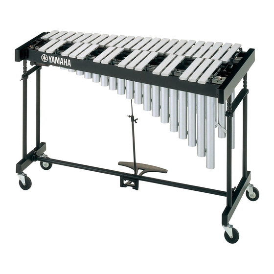
- Page 28 143 x 82 cm (56-1/4" x 32-1/4") Height Adjustment 81–89 cm (31-7/8" x 35") Weight 57 kg (125.6 lbs) Oversized Castors 4" high YV-1600A Range f–f3, 3 Octaves Bars Aluminum Alloy, 1-1/2" wide, 1/2" thick Pitch A = 442 Hz Drive Unit YVM-200 (Pause Controller), 25–150 rpm...