Table of Contents
Advertisement
Advertisement
Table of Contents

Related Manuals for Asus M4A79XTD - Motherboard - ATX


Summary of Contents for Asus M4A79XTD - Motherboard - ATX
- Page 1 M4A79XTD EVO...
- Page 2 Product warranty or service will not be extended if: (1) the product is repaired, modified or altered, unless such repair, modification of alteration is authorized in writing by ASUS; or (2) the serial number of the product is defaced or missing.
-
Page 3: Table Of Contents
Package contents..................1-1 Special features..................1-2 1.3.1 Product highlights................ 1-2 1.3.2 ASUS unique features..............1-3 1.3.3 ASUS intelligent performance and overclocking features ... 1-5 Chapter 2: Hardware information Before you proceed ................... 2-1 Motherboard overview ................2-2 2.2.1 Motherboard layout ..............2-2 2.2.2... - Page 4 BIOS setup Knowing BIOS .................... 3-1 Updating BIOS .................... 3-1 3.2.1 ASUS Update utility..............3-2 3.2.2 ASUS EZ Flash 2 utility ............... 3-4 3.2.3 ASUS CrashFree BIOS 3 utility........... 3-5 BIOS setup program .................. 3-6 3.3.1 BIOS menu screen ..............3-6 3.3.2...
- Page 5 Boot Device Priority..............3-25 3.7.2 Boot Settings Configuration ............3-26 3.7.3 Security ..................3-27 Tools menu ....................3-29 3.8.1 ASUS EZ Flash 2 ..............3-29 3.8.2 Express Gate ................3-29 3.8.3 ASUS O.C. Profile ..............3-30 3.8.4 AI NET 2 ..................3-31 Exit menu ....................
- Page 6 Contents Chapter 5: CrossFireX™ technology support ® CrossFireX™ technology ..............5-1 ® 5.1.1 Requirements ................5-1 5.1.2 Before you begin ................. 5-1 Installing CrossFireX™ graphics cards ........... 5-2 Software information ................. 5-3 5.3.1 Installing the device drivers ............5-3 5.3.2 Enabling the ATI CrossFireX™...
-
Page 7: Notices
Complying with the REACH (Registration, Evaluation, Authorisation, and Restriction of Chemicals) regulatory framework, we published the chemical substances in our products at ASUS REACH website at http://green.asus.com/english/REACH.htm. DO NOT throw the motherboard in municipal waste. This product has been designed to enable proper reuse of parts and recycling. -
Page 8: Safety Information
Safety information Electrical safety • To prevent electrical shock hazard, disconnect the power cable from the electrical outlet before relocating the system. • When adding or removing devices to or from the system, ensure that the power cables for the devices are unplugged before the signal cables are connected. If possible, disconnect all power cables from the existing system before you add a device. -
Page 9: About This Guide
Where to find more information Refer to the following sources for additional information and for product and software updates. ASUS websites The ASUS website provides updated information on ASUS hardware and software products. Refer to the ASUS contact information. Optional documentation Your product package may include optional documentation, such as warranty flyers, that may have been added by your dealer. -
Page 10: Conventions Used In This Guide
Conventions used in this guide To ensure that you perform certain tasks properly, take note of the following symbols used throughout this manual. DANGER/WARNING: Information to prevent injury to yourself when trying to complete a task. CAUTION: Information to prevent damage to the components when trying to complete a task. -
Page 11: M4A79Xtd Evo Specifications Summary
4 x 240-pin DIMM slots support maximum 16GB unbuffered ECC and non-ECC DDR3 1800 (O.C.) / 1600 / 1333 / 1066 MHz memory modules * Refer to www.asus.com for the latest Memory QVL (Qualified Vendors List). ** When you install a total memory of 4GB or more, Windows ®... - Page 12 - ASUS Anti-Surge Protection ASUS Green Design: - ASUS EPU ASUS Express Gate ASUS Quiet Thermal Solution: - ASUS Fanless Design: Stylish heat sink solution - ASUS Q-Fan 2 ASUS EZ DIY: - ASUS Q-Shield - ASUS Q-Connector - ASUS CrashFree BIOS 3 - ASUS O.C.
- Page 13 1 x 4-pin ATX 12V power connector BIOS 8Mb Flash ROM, AMI BIOS, PnP, DMI2.0, WfM2.0, SM BIOS 2.3, ACPI2.0a, ASUS EZ Flash 2, ASUS CrashFree BIOS 3 Manageability WOL by PME, WOR by PME, WOR by Ring, PXE, Chassis intrusion...
-
Page 15: Chapter 1: Product Introduction
® The motherboard delivers a host of new features and latest technologies, making it another standout in the long line of ASUS quality motherboards! Before you start installing the motherboard, and hardware devices on it, check the items in your package with the list below. -
Page 16: Special Features
Green ASUS This motherboard and its packaging comply with the European Union’s Restriction on the use of Hazardous Substances (RoHS). This is in line with the ASUS vision of creating environment-friendly and recyclable products/packaging to safeguard consumers’ health while minimizing the impact on the environment. -
Page 17: Asus Unique Features
- helping save power and money! Express Gate Express Gate is an ASUS exclusive OS that provides you with quick access to the Internet and key applications before entering the Windows OS. Refer to pages 3-29, 3-30 and 4-10 ®... -
Page 18: Asus Quiet Thermal Solution
Q-Fan 2 ASUS Q-Fan 2 technology intelligently adjusts both CPU fan and chassis fan speeds according to system loading to ensure quiet, cool and efficient operation. ASUS Crystal Sound This feature can enhance speech-centric applications like Skype, online game, video conference and recording. -
Page 19: Asus Intelligent Performance And Overclocking Features
ASUS intelligent performance and overclocking features TurboV Feel the adrenaline rush of real-time OC—now a reality with the ASUS TurboV. This easy OC tool allows you to overclock without exiting or rebooting the OS; and its user-friendly interface makes overclock with just a few clicks away. Moreover, the ASUS OC profiles in TurboV provides the best O.C. - Page 20 Chapter 1: Product Introduction...
-
Page 21: Chapter 2: Hardware Information
ON, in sleep mode, or in soft-off mode. This is a reminder that you should shut down the system and unplug the power cable before removing or plugging in any motherboard component. The illustration below shows the location of the onboard LED. ASUS M4A79XTD EVO... -
Page 22: Motherboard Overview
Motherboard overview 2.2.1 Motherboard layout Refer to 2.7 Connectors for more information about rear panel connectors and internal connectors. Chapter 2: Hardware information... -
Page 23: Layout Contents
Chassis intrusion connector (4-1 pin CHASSIS) 2-29 CPU overvoltage setting (3-pin OV_CPU) 2-20 Optical drive audio connector (4-pin CD) 2-33 Front panel audio connector (10-1 pin AAFP) 2-30 Digital audio connector (4-1 pin SPDIF_OUT) 2-30 Onboard power LED (SB_PWR) ASUS M4A79XTD EVO... -
Page 24: Placement Direction
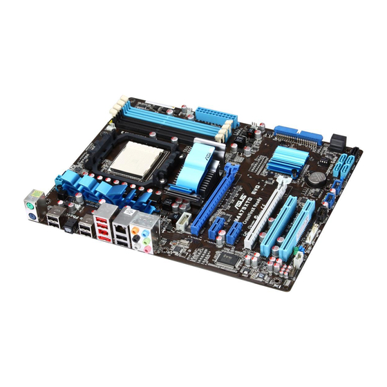
2.2.3 Placement direction When installing the motherboard, ensure that you place it into the chassis in the correct orientation. The edge with external ports goes to the rear part of the chassis as indicated in the image below. 2.2.4 Screw holes Place nine screws into the holes indicated by circles to secure the motherboard to the chassis. -
Page 25: Central Processing Unit (Cpu)
Press the lever sideways to unlock the socket, then lift it up to a 90˚ angle. Socket lever Make sure that the socket lever is lifted up to a 90˚ angle. Otherwise, the CPU will not fit in completely. ASUS M4A79XTD EVO... - Page 26 Position the CPU above the socket such that the CPU corner with the gold triangle matches the socket corner with a small triangle. Carefully insert the CPU into the socket until it fits in place. Gold triangle Small triangle When the CPU is in place, push down the socket lever to secure the CPU.
-
Page 27: Installing The Cpu Heatsink And Fan
Retention module base Your boxed CPU heatsink and fan assembly should come with installation instructions for the CPU, heatsink, and the retention mechanism. If the instructions in this section do not match the CPU documentation, follow the latter. ASUS M4A79XTD EVO... - Page 28 Attach one end of the retention bracket to the retention module base. Align the other end of the retention bracket (near the retention bracket lock) to the retention module base. A clicking sound denotes that the retention bracket is in place. Ensure that the fan and heatsink assembly perfectly fits the retention mechanism module base, otherwise...
- Page 29 CPU_FAN. • Do not forget to connect the CPU fan connector! Hardware monitoring errors can occur if you fail to plug this connector. • This connector is backward compatible with old 3-pin CPU fan. ASUS M4A79XTD EVO...
-
Page 30: System Memory
System memory 2.4.1 Overview The motherboard comes with four Double Data Rate 3 (DDR3) Dual Inline Memory Modules (DIMM) sockets. A DDR3 module has the same physical dimensions as a DDR2 DIMM but is notched differently to prevent installation on a DDR2 DIMM socket. DDR3 modules are developed for better performance with less power consumption. -
Page 31: Memory Configurations
3.5 Advanced menu for manual memory frequency adjustment. • For system stability, use a more efficient memory cooling system to support a full memory load (4 DIMMs) or overclocking condition. ASUS M4A79XTD EVO 2-11... - Page 32 M4A79XTD EVO Motherboard Qualified Vendors Lists (QVL) DDR3-2000 (O.C.) MHz capability* DIMM socket support Chip Timing (optional) Vendor Part No. Size SS/DS Chip NO. Voltage Brand DIMM (BIOS) Kingston KHX16000D3K2/2GN(EPP) 2048MB(Kit of 2) SS Heat-Sink Package 9-9-9-27 1.5V • • DDR3-1800 (O.C.) MHz capability* DIMM socket support Chip...
- Page 33 K4B1G0846D-HCH9(ECC) • • • Super Talent W1333X2GB8 1024MB Heat-Sink Package • • • Transcend TS128MLK64V3U 1024MB SEC 813HCH9 K4B1G0846D • • • Transcend TS128MLK72V3U 1024MB K4B1G0846D(ECC) • • • Transcend TS256MLK64V3U 2048MB SEC816HCH9K4B1G0846D • • • ASUS M4A79XTD EVO 2-13...
- Page 34 C*: Supports four modules inserted into both the blue and black slots as two pairs of dual-channel memory configuration. • Ensure that you download and update to the latest BIOS at http://www.asus.com and purchase the memory modules listed in the ASUS official memory Qualified Vendors Lists (QVL).
-
Page 35: Installing A Dimm
DIMM. Support the DIMM lightly with your fingers when pressing the retaining clips. The DIMM might get damaged when it flips out with extra force. Remove the DIMM from the socket. ASUS M4A79XTD EVO 2-15... -
Page 36: Expansion Slots
Expansion slots In the future, you may need to install expansion cards. The following subsections describe the slots and the expansion cards that they support. Ensure to unplug the power cord before adding or removing expansion cards. Failure to do so may cause you physical injury and damage motherboard components. -
Page 37: Interrupt Assignments
– shared – – – – USB 2.0 controller – – – shared – – – – HD audio shared – – – – – – – Onboard SATA – – – – shared – – ASUS M4A79XTD EVO 2-17... -
Page 38: Pci Slots
2.5.4 PCI slots The PCI slots support cards such as a LAN card, SCSI card, USB card, and other cards that comply with PCI specifications. Refer to the figure below for the location of the slots. 2.5.5 PCI Express x1 slots This motherboard supports PCI Express x1 network cards, SCSI cards and other cards that comply with the PCI Express specifications. -
Page 39: Jumpers
• Due to the chipset behavior, AC power off is required to enable C.P.R. function. You must turn off and on the power supply or unplug and plug the power cord before rebooting the system. ASUS M4A79XTD EVO 2-19... - Page 40 CPU overvoltage setting (3-pin OV_CPU) This jumper allows you to enable or disable the advanced CPU overvoltage setting in BIOS. Read the following information before you change the jumper setting. Set to pins 1-2 to activate the advanced CPU overvoltage feature. OV_CPU Pins 2-3 (Default) up to 1.70V...
-
Page 41: Connectors
DO NOT insert a different connector to the external SATA port. To enable external SATA device hot-plugging, set the OnChip SATA Type in the BIOS • settings to [AHCI] mode, and then reboot the system. Refer to section 3.4.2 Storage Configuration for details. ASUS M4A79XTD EVO 2-21... -
Page 42: Audio I/O Connections
*LAN port LED indications ACT/LINK SPEED Activity Link LED Speed LED Status Description Status Description No link 10 Mbps connection ORANGE Linked ORANGE 100 Mbps connection LAN port BLINKING Data activity GREEN 1 Gbps connection **Audio 2, 4, 6, or 8-channel configuration Port Headset 4-channel... - Page 43 Connect to Stereo Speakers Connect to 2.1 channel Speakers Connect to 4.1 channel Speakers ASUS M4A79XTD EVO 2-23...
- Page 44 Connect to 5.1 channel Speakers Connect to 7.1 channel Speakers 2-24 Chapter 2: Hardware information...
-
Page 45: Internal Connectors
This prevents incorrect insertion when you connect the IDE cable. • Use the 80-conductor IDE cable for Ultra DMA 133/100/66 IDE devices. If any device jumper is set as “Cable-Select”, ensure that all other device jumpers have the same setting. ASUS M4A79XTD EVO 2-25... - Page 46 Serial ATA connectors (7-pin SATA1–6, SATA_E1) These connectors are for the Serial ATA signal cables for Serial ATA hard disk and optical disk drives. If you install SATA hard disk drives to the SATA1–6 connectors, you can create a RAID 0, RAID 1, RAID 5, RAID 10 or JBOD configuration through the onboard AMD ®...
- Page 47 These are not jumpers! Do not place jumper caps on the fan connectors! • Only the 4-pin CPU_FAN and 4-pin CHA_FAN 1 connectors support the ASUS Q-FAN 2 feature. • If you install two VGA cards, we recommend that you plug the rear chassis fan cable to the motherboard connector labled CHA_FAN1 or CHA_FAN2 for better themal environment.
-
Page 48: Usb Connectors
Never connect a 1394 cable to the USB connectors. Doing so will damage the motherboard! You can connect the front panel USB cable to the ASUS Q-Connector (USB, blue) first, and then install the Q-Connector (USB) to the USB connector onboard if your chassis supports front panel USB ports. - Page 49 The signal is then generated as a chassis intrusion event. By default , the pin labeled “Chassis Signal” and “Ground” are shorted with a jumper cap. Remove the jumper caps only when you intend to use the chassis intrusion detection feature. ASUS M4A79XTD EVO 2-29...
- Page 50 Digital audio connector (4-1 pin SPDIF_OUT) This connector is for an additional Sony/Philips Digital Interface (S/PDIF) port. Connect the S/PDIF Out module cable to this connector, then install the module to a slot opening at the back of the system chassis. The S/PDIF module is purchased separately.
- Page 51 If you want to use two high-end PCI Express x16 cards, use a PSU with 1000W power or above to ensure the system stability. • If you are uncertain about the minimum power supply requirement for your system, refer to the Recommended Power Supply Wattage Calculator at http://support.asus. com/PowerSupplyCalculator/PSCalculator.aspx?SLanguage=en-us for details. ASUS M4A79XTD EVO 2-31...
-
Page 52: System Panel Connector
System panel connector (20-8 pin PANEL) This connector supports several chassis-mounted functions. • System power LED (2-pin PLED) This 2-pin connector is for the system power LED. Connect the chassis power LED cable to this connector. The system power LED lights up when you turn on the system power, and blinks when the system is in sleep mode. - Page 53 This connector is for a serial (COM) port. Connect the serial port module cable to this connector, then install the module to a slot opening at the back of the system chassis. The COM module is purchased separately. ASUS M4A79XTD EVO 2-33...
-
Page 54: Asus Q-Connector (System Panel)
2.7.4. ASUS Q-Connector (system panel) Use the ASUS Q-Connector to connect/disconnect the chassis front panel cables. Connect the front panel cables to the ASUS Q-Connector. Refer to the labels on the Q-Connector to know the detailed pin definitions, and then match them to their respective front panel cable labels. -
Page 55: Starting Up For The First Time
BIOS setting. Pressing the power switch for more than four seconds lets the system enter the soft-off mode regardless of the BIOS setting. Refer to section 3.6 Power Menu for details. ASUS M4A79XTD EVO 2-35... - Page 56 2-36 Chapter 2: Hardware information...
-
Page 57: Chapter 3: Bios Setup
Refer to the corresponding sections for details on these utilities. Save a copy of the original motherboard BIOS file to a USB flash drive in case you need to restore the BIOS in the future. Copy the original motherboard BIOS using the ASUS Update utility. -
Page 58: Asus Update Utility
3.2.1 ASUS Update utility The ASUS Update is a utility that allows you to manage, save, and update the motherboard BIOS in Windows environment. The ASUS Update utility allows you to: ® • Save the current BIOS file • Download the latest BIOS file from the Internet •... - Page 59 Auto Select. Click Next. Next. Follow the onscreen instructions to complete the update process. The ASUS Update utility is capable of updating itself through the Internet. Always update the utility to avail all its features. Updating the BIOS through a BIOS file...
-
Page 60: Asus Ez Flash 2 Utility
3.2.2 ASUS EZ Flash 2 utility The ASUS EZ Flash 2 feature allows you to update the BIOS without having to use a bootable floppy disk or an OS-based utility. Before you start using this utility, download the latest BIOS from the ASUS website at www. -
Page 61: Asus Crashfree Bios 3 Utility
The BIOS file in the motherboard support DVD may be older than the BIOS file published on the ASUS official website. If you want to use the newer BIOS file, download the file at support.asus.com and save it to a USB flash drive. -
Page 62: Bios Setup Program
BIOS setup program A BIOS Setup program is provided for BIOS item modification. When you start up the computer, the system provides you with the opportunity to run this program. Press <Del> during the Power-On Self-Test (POST) to enter the Setup utility. Otherwise, POST continues with its test routines. -
Page 63: Navigation Keys
<Page Up> / <Page Down> keys to Pop-up window display the other items on the screen. 3.3.9 General help At the top right corner of the menu screen is a brief description of the selected item. ASUS M4A79XTD EVO... -
Page 64: Main Menu
Main menu When you enter the BIOS Setup program, the Main menu screen appears, giving you an overview of the basic system information. Refer to 3.3.1 BIOS menu screen for information on the menu screen items and how to navigate through them. BIOS SETUP UTILITY Main Advanced... - Page 65 (Ultra DMA). Setting to [Auto] allows automatic selection of the DMA mode. SMART Monitoring [Auto] [Auto] Allows automatic selection of the S.M.A.R.T (Smart Monitoring, Analysis, and Reporting Technology). [Enabled] Enables the S.M.A.R.T feature. [Disabled] Disables the S.M.A.R.T feature. ASUS M4A79XTD EVO...
-
Page 66: Storage Configuration
32Bit Data Transfer [Enabled] [Enabled] Sets the IDE/SATA controller to combine two 16-bit reads from the hard disk into a single 32-bit double word transfer to the processor. This makes more efficient use of the PCI bus as fewer transactions are needed for the transfer of a particular amount of data. -
Page 67: System Information
JumperFree Configuration Adjust system CPU Configuration frequency/voltage Chipset Onboard Devices Configuration USB Configuration PCIPnP Select Screen ←→ Select Item ↑↓ Enter Go to Sub Screen General Help Save and Exit Exit v02.61 (C)Copyright 1985-2009, American Megatrends, Inc. ASUS M4A79XTD EVO 3-11... -
Page 68: Jumperfree Configuration
3.5.1 JumperFree Configuration The items shown in this screen may be different due to the CPU you installed. BIOS SETUP UTILITY Main Advanced Power Boot Tools Exit Select the target CPU Configure System Frequency/Voltage frequency, and the Ai Overclock Tuner [Auto] relevant parameters will be auto-adjusted. - Page 69 Allows you to enable or disable the DDR3 memory profile function. Configuration options: [Disabled] [Enabled] DRAM Voltage [Auto] Allows you to set the DRAM voltage. The values range from 1.50V to 2.50V with a 0.02V interval. Use the <+> and <-> keys to adjust the value. ASUS M4A79XTD EVO 3-13...
- Page 70 DRAM Timing/Driving Configuration Advanced DRAM Timing/Driving Configuration DRAM Command Rate: 1T: DRAM address and DRAM Command Rate [Auto] control signals are DRAM 1st Information : 6-6-6-15-4-20-6-4 driven for one MEMCLK cycle. The configuration options for some of the following items vary depending on the DIMMs you install on the motherboard.
- Page 71 • Setting the voltages to a high level may damage the CPU, memory module, and chipset permanently. Proceed with caution. • The system may require a better cooling system to work stably under high voltage settings. ASUS M4A79XTD EVO 3-15...
-
Page 72: Cpu Configuration
3.5.2 CPU Configuration The items in this menu show the CPU-related information that the BIOS automatically detects. The items shown in this screen may be different due to the CPU you installed. BIOS SETUP UTILITY Advanced CPU Configuration This option should remain disabled for AMD Phenom(tm) II X4 945 Processor the normal operation. -
Page 73: Chipset
Set to [Good] to adjust ECC mode automatically. Set to [Super] to adjust the DRAM BG Scrub sub-item manually. [Super] [Max] Set to [Max] to adjust ECC mode automatically. [User] Set to [User] to adjust the all sub-items manually. ASUS M4A79XTD EVO 3-17... -
Page 74: Onboard Devices Configuration
DRAM ECC Enable [Disabled] [Disabled] Disables this function. [Enabled] Allows hardware to report and correct memory errors automatically, maintaining system integrity. DRAM SCRUB REDIRECT [Disabled] [Disabled] Disables this function. [Enabled] Allows the system to correct the DRAM ECC errors immediately when they occur. 4-Bit ECC Mode [Disabled] [Disabled] Disables the CHIPKILL ECC mode. -
Page 75: Usb Configuration
<Enter> to display the configuration options. BIOS SETUP UTILITY Advanced USB Configuration Options Module Version - 2.24.5-13.4 Disabled Enabled USB Devices Enabled: None USB Support [Enabled] Legacy USB Support [Auto] USB 2.0 Controller [Enabled] USB 2.0 Controller Mode [HiSpeed] ASUS M4A79XTD EVO 3-19... -
Page 76: Pcipnp
The USB Devices Enabled item shows the auto-detected values. If no USB device is detected, the item shows None. USB Support [Enabled] [Enabled] Enables the USB Host Controllers. [Disabled] Disables the controllers. The following items appear only when you set USB Support to [Enabled]. Legacy USB Support [Enabled] [Auto] Allows the system to detect the presence of USB devices at startup. -
Page 77: Power Menu
When set to [Disabled], the system disable the Advanced Configuration and Power Interface (ACPI) support in the Advanced Programmable Interrupt Controller (APIC). [Enabled] When set to [Enabled], the ACPI APIC table pointer is included in the RSDT pointer list. ASUS M4A79XTD EVO 3-21... -
Page 78: Apm Configuration
3.6.4 APM Configuration BIOS SETUP UTILITY Power APM Configuration Options Restore on AC Power Loss [Power Off] Power On By PME [Disabled] Power On Power On By PS/2 Keyboard [Disabled] Power Off Last State Power On By PS/2 Mouse [Disabled] Power On By Ring [Disabled] Power On By RTC Alarm... -
Page 79: Hardware Monitor
Sets to [Performance] to achieve maximum CPU fan speed. [Optimal] Sets to [Optimal] to make the CPU fan automatically adjust depending on the CPU temperature. [Silent] Sets to [Silent] to minimize the fan speed for quiet CPU fan operation. ASUS M4A79XTD EVO 3-23... - Page 80 Chassis Q-Fan Function [Disabled] [Disabled] Disables the Chassis Q-Fan control feature. [Enabled] Enables the Chassis Q-Fan control feature. The following item appears only when you set Chassis Q-Fan Function to [Enabled]. Chassis Q-Fan Mode [Silent] [Performance] Sets to [Performance] to achieve maximum chassis fan speed. [Optimal] Sets to [Optimal] to make the chassis fan automatically adjust depending on the chassis temperature.
-
Page 81: Boot Menu
Configuration options: [Removable Dev.] [Hard Drive] [ATAPI CD-ROM] [Disabled] • To select the boot device during system startup, press <F8> when ASUS Logo appears. • To access Windows OS in Safe Mode, do any of the following: ®... -
Page 82: Boot Settings Configuration
Enables the full screen logo display feature. [Disabled] Disables the full screen logo display feature. Set this item to [Enabled] to use the ASUS MyLogo 2™ feature. AddOn ROM Display Mode [Force BIOS] [Force BIOS] The third-party ROM messages will be forced to display during the boot sequence. -
Page 83: Security
[View Only] Allows access but does not allow change to any field. [Limited] Allows changes only to selected fields, such as Date and Time. [Full Access] Allows viewing and changing all the fields in the Setup utility. ASUS M4A79XTD EVO 3-27... - Page 84 Change User Password Select this item to set or change the user password. The User Password item on top of the screen shows the default Not Installed. After you set a password, this item shows Installed. To set a User Password: Select the Change User Password item and press <Enter>.
-
Page 85: Tools Menu
3.8.1 ASUS EZ Flash 2 Allows you to run ASUS EZ Flash 2. When you press <Enter>, a confirmation message appears. Use the left/right arrow key to select between [Yes] or [No], then press <Enter> to confirm your choice. See section 3.2.2 ASUS EZ Flash 2 utility for details. -
Page 86: Asus O.c. Profile
Express Gate. The first time wizard will run again when you enter the Express Gate environment after clearing its settings. 3.8.3 ASUS O.C. Profile This item allows you to store or load multiple BIOS settings. BIOS SETUP UTILITY Tools O.C. PROFILE Configuration... -
Page 87: Ai Net 2
(POST). It takes 3 to 10 seconds to diagnose the LAN cable. [Disabled] BIOS will not check the Realtek LAN cable during the Power-On Self-Test (POST). [Enabled] BIOS checks the Realtek LAN cable during the Power-On Self-Test (POST). ASUS M4A79XTD EVO 3-31... -
Page 88: Exit Menu
Exit menu The Exit menu items allow you to load the optimal or failsafe default values for the BIOS items, and save or discard your changes to the BIOS items. BIOS SETUP UTILITY Main Advanced Power Boot Tools Exit Exit system setup Exit Options after saving the changes. -
Page 89: Chapter 4: Software Support
The contents of the support DVD are subject to change at any time without notice. Visit the ASUS website at www.asus.com for updates. 4.2.1 Running the support DVD Place the support DVD into the optical drive. -
Page 90: Obtaining The Software Manuals
4.2.2 Obtaining the software manuals The software manuals are included in the support DVD. Follow the instructions below to get the necessary software manuals. The software manual files are in Portable Document Format (PDF). Install the Adobe ® Acrobat Reader from the Utilities menu before opening the files. ®... -
Page 91: Software Information
Launching PC Probe II Install PC Probe II from the motherboard support DVD. Launch PC Probe II by clicking Start > Programs > ASUS > PC Probe II > PC Probe II v1.xx.xx. The PC Probe II main window appears. -
Page 92: Cool 'N' Quiet!™ Technology
Launching the Cool ‘n’ Quiet!™ software Install Cool ‘n’ Quiet!™ software from the motherboard support DVD. Click Start > Programs > ASUS > Cool & Quiet > Cool & Quiet. The Cool ‘n’ Quiet!™ technology screen appears and displays the current CPU Frequency and CPU Voltage. -
Page 93: Asus Ai Suite
ASUS AI Suite allows you to launch several ASUS utilities easily. Launching AI Suite Install AI Suite from the motherboard support DVD. Launch AI Suite by clicking Start > Programs > ASUS > AI Suite > AI Suite v1.xx.xx. The AI Suite main window appears. The AI Suite icon appears in the Windows notification area. -
Page 94: Asus Epu
4.3.4 ASUS EPU ASUS EPU is an energy-efficient tool that provides you with a total system power-saving solution. It detects the current computer loading and intelligently adjusts the power in real- time. With auto phase switching for components, the EPU automatically provides the most... -
Page 95: Asus Q-Fan 2
4.3.5 ASUS Q-Fan 2 This ASUS Q-Fan 2 Control feature allows you to set the appropriate performance level of the CPU Q-Fan 2 or the Chassis Q-Fan 2 for more efficient system operation. After enabling the Q-Fan 2 function, the fans can be set to automatically adjust depending on the temperature, to decrease fan speed, or to achieve the maximum fan speed. -
Page 96: Asus Turbov
4.3.6 ASUS TurboV ASUS TurboV allows you to easily overclock without exiting or rebooting the OS, and set up the best O.C. settings for different scenarios. Refer to the CPU documentation before adjusting CPU voltage settings. Setting a high voltage may damage the CPU permanently, and setting a low voltage may make the system unstable. -
Page 97: Asus Turbo Key
4.3.7 ASUS Turbo Key ASUS Turbo Key allows the user to turn the PC power button into a physical overclocking button. After the easy setup, Turbo Key can boost performances without interrupting ongoing work or games—with just one touch! Launching ASUS Turbo Key Install ASUS Turbo Key from the motherboard support DVD. -
Page 98: Asus Express Gate
4.3.8 ASUS Express Gate ASUS Express Gate is an instant-on environment that gives you quick access to the Internet, Skype, and viewing your pictures. Within a few seconds of powering on your computer, you will be at the Express Gate menu where you can start the web browser, Skype, or other Express Gate applications. -
Page 99: Via ® High Definition Audio Utility
VIA HD Audio Deck for Windows XP Display panel and volume control Minimize button Configuration options Control settings window Refer to the software manual in the support DVD or visit the ASUS website at www.asus.com for detailed software configuration. ASUS M4A79XTD EVO 4-11... -
Page 100: Raid Configurations
RAID configurations The motherboard comes with the AMD SB750 chipset that allows you to configure Serial ATA hard disk drives as RAID volumes. The motherboard supports the following RAID configurations: RAID 0, RAID 1, RAID 5, and RAID 10. • You must install Windows XP Service Pack 2 or later versions before using Serial ®... -
Page 101: Installing Serial Ata Hard Disks
During POST, press <Ctrl> + <F> to display the utility main menu. Option ROM Utility (c) 2008 Advanced Micro Devices, Inc. [ Main Menu ] View Drive Assignments..[1] Define LD.....[2] Delete LD.....[3] Controller Configuration..[4] [ Keys Available ] Press 1..4 to Select Option [ESC] Exit ASUS M4A79XTD EVO 4-13... -
Page 102: Creating A Raid Volume
The Main Menu allows you to select an operation to perform. The Main Menu options include: View Drive Assignments: shows the status of the hard disk drives. • Define LD: creates a RAID 0, RAID 1, RAID 5 or RAID 10 configuration. •... - Page 103 LD 7 ---- ---- -------- ---- LD 8 ---- ---- -------- ---- LD 9 ---- ---- -------- ---- LD 10 ---- ---- -------- ---- [ Keys Available ] [↑] Up [↓] Down [ESC] Exit [Enter] Select ASUS M4A79XTD EVO 4-15...
-
Page 104: Deleting A Raid Configuration
Deleting a RAID configuration Take caution when deleting a RAID volume. You will lose all data on the hard disk drives when you delete a RAID volume. To delete a RAID volume In the Main Menu, press <3> to enter the Delete LD function. Select the RAID item you want to delete and press <Del>... -
Page 105: Creating A Raid Driver Disk
Press <F6>, and then insert the floppy disk with RAID driver into the floppy disk drive. When prompted to select the SCSI adapter to install, ensure that you select SB 750. Follow the succeeding screen instructions to complete the installation. ASUS M4A79XTD EVO 4-17... -
Page 106: Using A Usb Floppy Disk Drive
To install the RAID driver in Windows Vista ® Insert the floppy disk with RAID driver into the floppy disk drive. During the OS installation, select SB 750. Follow the succeeding screen instructions to complete the installation. 4.5.4 Using a USB floppy disk drive Due to OS limitation, Windows XP may not recognize the USB floppy disk drive when you ®... - Page 107 [HardwareIds.scsi.iastor_ICH8RICH9RICH10RDO] sections in the txtsetup.oem file. Type the following line to the bottom of the two sections: id = “USB\VID_xxxx&PID_xxxx”, “usbstor” Add the same line to both sections. The VID and PID vary with different vendors. Save and exit the file. ASUS M4A79XTD EVO 4-19...
- Page 108 4-20 Chapter 4: Software support...
-
Page 109: Chapter 5: Ati ® Crossfirex™ Technology Support
For Windows XP, go to Control Panel > Add/Remove Programs. For Windows Vista, go to Control Panel > Programs and Features. Select your current graphics card driver/s. For Windows XP, select Add/Remove. For Windows Vista, select Uninstall. Turn off your computer. ASUS M4A79XTD EVO... -
Page 110: Installing Crossfirex™ Graphics Cards
Installing CrossFireX™ graphics cards The following pictures are for reference only. The graphics cards and the motherboard layout may vary with models, but the installation steps remain the same. Prepare two CrossFireX-ready graphics cards. Insert the two graphics card into the PCIEX16 slots. -
Page 111: Software Information
ATI icon in the Windows notification area and select Cayalist Control Center. The Catalyst Control Center Setup Assistant appears when the system detects the existance of multi-graphics cards. Click Go to continue to the Catalyst Control Center Advanced View window. ASUS M4A79XTD EVO... - Page 112 Enabling CrossFireX technology In the Catalyst Control Center window, click Graphics Settings > CrossFireX > Configure. From the Graphics Adapter list, select the graphics card to act as the display GPU. Select Enable CrossFireX. Click Apply, and then click OK to exit the window.