Table of Contents
Advertisement
Advertisement
Table of Contents

Related Manuals for Asus M4A785TD-V EVO - Motherboard - ATX


Summary of Contents for Asus M4A785TD-V EVO - Motherboard - ATX
- Page 1 M4A785TD-V EVO...
- Page 2 Product warranty or service will not be extended if: (1) the product is repaired, modified or altered, unless such repair, modification of alteration is authorized in writing by ASUS; or (2) the serial number of the product is defaced or missing.
-
Page 3: Table Of Contents
Welcome! ..................1-1 Package contents ................. 1-1 Special features ................1-1 1.3.1 Product highlights ............1-1 1.3.2 Innovative ASUS features ..........1-3 Before you proceed ..............1-5 Motherboard overview ..............1-6 1.5.1 Placement direction ............1-6 1.5.2 Screw holes ..............1-6 1.5.3... - Page 4 BIOS information Managing and updating your BIOS ..........2-1 2.1.1 ASUS Update utility ............2-1 2.1.2 ASUS EZ Flash 2 utility ........... 2-2 2.1.3 ASUS CrashFree BIOS 3 utility ........2-3 BIOS setup program ..............2-4 2.2.1 BIOS menu screen ............2-5 2.2.2...
- Page 5 Boot Device Priority ............2-18 2.6.2 Boot Settings Configuration .......... 2-18 2.6.3 Security ................. 2-19 Tools menu ................. 2-20 2.7.1 ASUS EZ Flash 2 ............2-20 2.7.2 Express Gate ..............2-21 2.7.3 AI NET 2................ 2-21 Exit menu ..................2-22...
-
Page 6: Notices
Complying with the REACH (Registration, Evaluation, Authorisation, and Restriction of Chemicals) regulatory framework, we published the chemical substances in our products at ASUS REACH website at http://green.asus.com/english/REACH.htm. DO NOT throw the motherboard in municipal waste. This product has been designed to enable proper reuse of parts and recycling. -
Page 7: Safety Information
Safety information Electrical safety • To prevent electric shock hazard, disconnect the power cable from the electric outlet before relocating the system. • When adding or removing devices to or from the system, ensure that the power cables for the devices are unplugged before the signal cables are connected. If possible, disconnect all power cables from the existing system before you add a device. -
Page 8: About This Guide
Refer to the following sources for additional information and for product and software updates. ASUS websites The ASUS website provides updated information on ASUS hardware and software products. Refer to the ASUS contact information. Optional documentation Your product package may include optional documentation, such as warranty flyers, that may have been added by your dealer. -
Page 9: M4A785Td-V Evo Specifications Summary
4 x 240-pin DIMM slots support maximum 16GB unbuffered ECC and non-ECC DDR3 1800 (O.C.) / 1600 (O.C.) / 1333 / 1066 MHz memory modules Refer to www.asus.com for the latest Memory QVL (Qualified Vendors List). ** When you install a total memory of 4GB or more,... - Page 10 - 8+2 Phase Power Design ASUS Green Design: - ASUS EPU ASUS Expree Gate ASUS Quiet Thermal Solution: - ASUS Fanless Design: Stylish heat sink solution - ASUS Q-Fan ASUS EZ DIY: - ASUS CrashFree BIOS 3 - ASUS MyLogo 2...
- Page 11 1 x 24-pin EATX power connector 1 x 4-pin ATX 12V power connector BIOS 8Mb Flash ROM, AMI BIOS, PnP, DMI2.0, WfM2.0, SM BIOS 2.5, ACPI2.0a, ASUS EZ Flash 2, ASUS CrashFree BIOS 3 Manageability WOL by PME, WOR by PME, WOR by Ring, PXE...
-
Page 13: Chapter 1: Product Introduction
® The motherboard delivers a host of new features and latest technologies, making it another standout in the long line of ASUS quality motherboards! Before you start installing the motherboard, and hardware devices on it, check the items in your package with the list below. - Page 14 HyperTransport™ 3.0 support HyperTransport™ 3.0 technology provides 2.6 times more bandwidth than HT1.0 that radically improves system efficiency for a smoother and faster computing environment. SidePort Memory This motherboard features SidePort Memory, an individual onboard DDR3 memory serving as memory buffer for integrated graphics. With low CPU usage, the SidePort Memory provides integrated graphics acceleration.
-
Page 15: Innovative Asus Features
2 phase power dedicated to integrated memory/HT controller. ASUS Turbo Key ASUS Turbo Key allows you to turn the PC power button into an overclocking button. After the easy setup, Turbo Key boosts performances without interrupting ongoing work or games, simply through pressing the button. -
Page 16: Asus Express Gate
BIOS file using the bundled support DVD or a USB flash disk that contains the BIOS file. ASUS EZ Flash 2 ASUS EZ Flash 2 allows you to update the BIOS from a USB flash disk before entering the OS. ASUS Q-Fan ASUS Q-Fan technology intelligently adjusts CPU fan speeds according to system loading to ensure a quiet, cool, and efficient operation. -
Page 17: Before You Proceed
This motherboard and its packaging comply with the European Union’s Restriction on the use of Hazardous Substances (RoHS). This is in line with the ASUS vision of creating environment-friendly and recyclable products/packaging to safeguard consumers’ health while minimizing the impact on the environment. -
Page 18: Motherboard Overview
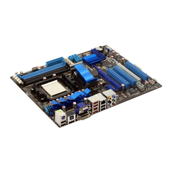
Motherboard overview 1.5.1 Placement direction When installing the motherboard, ensure that you place it into the chassis in the correct orientation. The edge with external ports goes to the rear part of the chassis as indicated in the image below. 1.5.2 Screw holes Place nine screws into the holes indicated by circles to secure the motherboard to the... -
Page 19: Motherboard Layout
14. Front panel audio connector (10-1 pin AAFP) 1-27 Onboard power LED (SB_PWR) 15. Serial port connector (10-1 pin COM1) 1-28 Clear RTC RAM (3-pin CLRTC) 1-18 16. PCIe x16 / PCIe x1 / PCI slots 1-17 ASUS M4A785TD-V EVO... -
Page 20: Central Processing Unit (Cpu)
Central Processing Unit (CPU) This motherboard comes with an AM3 socket designed for Phenom™ II / Athlon™ II / Sempron™ 100 series processors. The AM3 socket has a different pinout from the AM2+/AM2 socket. Ensure that you use a CPU designed for the AM3 socket. The CPU fits in only one correct orientation. DO NOT force the CPU into the socket to prevent bending the pins and damaging the CPU! 1.6.1 Installing the CPU... - Page 21 Connect the CPU fan cable to the CPU_FAN connector on the motherboard. DO NOT forget to connect the CPU fan connector! Hardware monitoring errors can occur if you fail to plug this connector. ASUS M4A785TD-V EVO...
-
Page 22: Installing The Heatsink And Fan
1.6.2 Installing the heatsink and fan Ensure that you use only AMD-certified heatsink and fan assembly. To install the CPU heatsink and fan: Place the heatsink on top of the installed CPU, ensuring that the heatsink fits properly on the retention module base. •... -
Page 23: System Memory
DDR2 DIMM socket. DDR3 modules are developed for better performance with less power consumption. The figure illustrates the location of the DDR3 DIMM sockets: Channel Sockets Channel A DIMM_A1 and DIMM_A2 Channel B DIMM_B1 and DIMM_B2 ASUS M4A785TD-V EVO 1-11... -
Page 24: Memory Configurations
1.7.2 Memory configurations You may install 512MB, 1GB, 2GB, and 4GB unbuffered ECC and non-ECC DDR3 DIMMs into the DIMM sockets. • You may install varying memory sizes in Channel A and Channel B. The system maps the total size of the lower-sized channel for the dual-channel configuration. Any excess memory from the higher-sized channel is then mapped for single-channel operation. - Page 25 • • G.SKILL F3-1066CL9T-6GBNQ 6144MB(Kit of 3) Heat-Sink Package 9-9-9-24 • • • GEIL DDR3-1333 CL9-9-9-24 1024MB Heat-Sink Package • • • GEIL GV34GB1333C7DC 2048MB Heat-Sink Package 7-7-7-24 • • • (continued on the next page) ASUS M4A785TD-V EVO 1-13...
- Page 26 DDR3-1333MHz capability DIMM support Chip Vendor Part No. Size Chip NO. Brand GEIL DDR3-1333 CL9-9-9-24 6144MB(Kit of 3) Heat-Sink Package • • • Kingston KVR1333D3N9/1G 1024MB elpida J1108BABG-DJ-E • • • Kingston KVR1333D3N9/2G 2048MB elpida J1108BABG-DJ-E • • • Micron MT8JTF12864AY-1G4D1 1024MB Micron...
- Page 27 • C*: Supports two pairs of modules inserted into both the blue slots and the black slots as two pairs of dual-channel memory configuration. Visit the ASUS website at www.asus.com for the latest QVL. ASUS M4A785TD-V EVO 1-15...
-
Page 28: Installing A Dimm
1.7.3 Installing a DIMM Unplug the power supply before adding or removing DIMMs or other system components. Failure to do so can cause severe damage to both the motherboard and the components. Press the retaining clips outward to DIMM notch unlock a DIMM socket. -
Page 29: Expansion Slots
This motherboard supports PCI Express x1 network cards, SCSI cards, and other cards that comply with the PCI Express specifications. 1.8.5 PCI Express x16 slots This motherboard supports two ATI CrossFireX™ PCI Express x16 graphics cards that comply with the PCI Express specifications. ASUS M4A785TD-V EVO 1-17... -
Page 30: Jumpers
Jumpers Clear RTC RAM (CLRTC) This jumper allows you to clear the Real Time Clock (RTC) RAM in CMOS. You can clear the CMOS memory of date, time, and system setup parameters by erasing the CMOS RTC RAM data. The onboard button cell battery powers the RAM data in CMOS, which include system setup information such as system passwords. -
Page 31: Connectors
8-channel configurations, the function of this port becomes Front Speaker Out. Microphone port (pink). This port connects to a microphone. Side Speaker Out port (gray). This port connects to the side speakers in the 8-channel audio configuration. ASUS M4A785TD-V EVO 1-19... - Page 32 Refer to the audio configuration table below for the function of the audio ports in the 2, 4, 6, or 8-channel configuration. Audio 2, 4, 6, or 8-channel configuration Headset Port 4-channel 6-channel 8-channel 2-channel Light Blue Line In Line In Line In Line In Lime...
-
Page 33: Internal Connectors
This connector is for an IEEE 1394a port. Connect the IEEE 1394a module cable to this connector, then install the module to a slot opening at the back of the system chassis. Never connect a USB cable to the IEEE 1394a connector. Doing so will damage the motherboard! ASUS M4A785TD-V EVO 1-21... -
Page 34: Atx Power Connectors (24-Pin Eatxpwr, 4-Pin Atx12V)
The system may become unstable or may not boot up if the power is inadequate. • If you are uncertain about the minimum power supply requirement for your system, refer to the Recommended Power Supply Wattage Calculator at http://support.asus. com/PowerSupplyCalculator/PSCalculator.aspx?SLanguage=en-us for details. 1-22... -
Page 35: Ide Connector (40-1 Pin Pri_Ide)
This prevents incorrect insertion when you connect the IDE cable. • Use the 80-conductor IDE cable for Ultra DMA 133/100/66 IDE devices. If any device jumper is set as “Cable-Select”, ensure that all other device jumpers have the same setting. ASUS M4A785TD-V EVO 1-23... - Page 36 Serial ATA connectors (7-pin SATA1, SATA2, SATA3, SATA5, and SATA6) These connectors are for the Serial ATA signal cables for Serial ATA 3Gb/s hard disk and optical disk drives. The Serial ATA 3Gb/s is backward compatible with Serial ATA 1.5Gb/s specification. The data transfer rate of the Serial ATA 3Gb/s is faster than the standard parallel ATA with 133 MB/s (Ultra DMA133).
-
Page 37: System Panel Connector (20-8 Pin Panel)
BIOS settings. Pressing the power switch for more than four seconds while the system is ON turns the system OFF. • Reset button (2-pin RESET) This 2-pin connector is for the chassis-mounted reset button for system reboot without turning off the system power. ASUS M4A785TD-V EVO 1-25... -
Page 38: Usb Connectors (10-1 Pin Usb78, Usb910, Usb1112)
USB connectors (10-1 pin USB78, USB910, USB1112) These connectors are for USB 2.0 ports. Connect the USB module cable to any of these connectors, then install the module to a slot opening at the back of the system chassis. These USB connectors comply with USB 2.0 specification that supports up to 480Mbps connection speed. -
Page 39: Front Panel Audio Connector (10-1 Pin Aafp)
• If you want to connect a high definition front panel audio module to this connector, set the Front Panel Select item in the BIOS to [HD Audio]. See section 2.4.4 Onboard Device Configuration for details. ASUS M4A785TD-V EVO 1-27... -
Page 40: Serial Port Connector (10-1 Pin Com1)
These are not jumpers! DO NOT place jumper caps on the fan connectors. Only the CPU fan supports the ASUS Q-Fan feature. Serial port connector (10-1 pin COM1) The connector is for a serial (COM) port. Connect the serial port module cable to the connector, then install the module to a slot opening at the back of the system chassis. -
Page 41: Software Support
The contents of the Support DVD are subject to change at any time without notice. Visit the ASUS website at www.asus.com for updates. To run the Support DVD Place the Support DVD into the optical drive. - Page 42 1-30 Chapter 1: Product introduction...
-
Page 43: Chapter 2: Bios Information
BIOS in the future. Copy the original motherboard BIOS using the ASUS Update utility. 2.1.1 ASUS Update utility The ASUS Update is a utility that allows you to manage, save, and update the motherboard BIOS in Windows environment. ®... -
Page 44: Update Bios Using Ez Flash 2
Follow the onscreen instructions to complete the updating process. 2.1.2 ASUS EZ Flash 2 utility The ASUS EZ Flash 2 feature allows you to update the BIOS without using an OS-based utility. Before you start using this utility, download the latest BIOS file from the ASUS website at www.asus.com. -
Page 45: Asus Crashfree Bios 3 Utility
2.1.3 ASUS CrashFree BIOS 3 utility The ASUS CrashFree BIOS 3 is an auto recovery tool that allows you to restore the BIOS file when it fails or gets corrupted during the updating process. You can update a corrupted BIOS file using the motherboard support DVD or a USB flash disk that contains the updated BIOS file. -
Page 46: Bios Setup Program
• The BIOS setup screens in this chapter are for reference only. They may not exactly match what you see on your screen. • Visit the ASUS website at www.asus.com to download the latest BIOS file for this motherboard. Chapter 2: BIOS information... -
Page 47: Bios Menu Screen
At the bottom right corner of a menu screen are the navigation keys for that particular menu. Use the navigation keys to select items in the menu and change the settings. Some of the navigation keys differ from one screen to another. ASUS M4A785TD-V EVO... -
Page 48: Menu Items
2.2.4 Menu items The highlighted item on the menu bar displays the specific items for that menu. For example, selecting Main shows the Main menu items. The other items (Advanced, Power, Boot, Tools, and Exit) on the menu bar have their respective menu items. -
Page 49: Main Menu
CD-ROM drive. Select [ARMD] (ATAPI Removable Media Device) if your device is either a ZIP, LS-120, or MO drive. Configuration options: [Not Installed] [Auto] [CDROM] [ARMD] This item only appears in the Primary IDE Master/Slave and SATA5/6 menus. ASUS M4A785TD-V EVO... -
Page 50: Sata Configuration
LBA/Large Mode [Auto] Enables or disables the LBA mode. Setting this item to [Auto] enables the LBA mode if the device supports this mode, and if the device was not previously formatted with LBA mode disabled. Configuration options: [Disabled] [Auto] Block (Multi-Sector Transfer) M [Auto] Enables or disables data multi-sectors transfers. -
Page 51: Advanced Menu
The following items only appear when you set CPU Overclocking to [Overclock Profile]. Overclock Options [Auto] Selects the overclocking profile. Configuration options: [Auto] [Overclock 2%] [Overclock 5%] [Overclock 8%] [Overclock 10%] GPU OverClocking [Auto] Allows you to select the GPU Overclocking. Configuration options: [Auto] [Manual] ASUS M4A785TD-V EVO... -
Page 52: Hyper Transport Configuration
The following item appears only when the GPU Overclocking item is set to [Manual]. GPU Engine Clock [500] Allows you to set the GPU frequency. The valid value is between 150 and 1000. PCIE Overclocking [Auto] Allows you to select the PCIE Overclocking. Configuration options: [Auto] [Manual] The following item appears only when the PCIE Overclocking item is set to [Manual]. - Page 53 Configuration options: [Auto] [4 CLK] ~ [7 CLK] tWRWR [Auto] Configuration options: [Auto] [3 CLK] ~ [10 CLK] tRDRD [Auto] Configuration options: [Auto] [3 CLK] ~ [10 CLK] tRFC0/1/2/3 [Auto] Configuration options: [Auto] [90ns] [110ns] [160ns] [300ns] [350ns] ASUS M4A785TD-V EVO 2-11...
-
Page 54: Cpu Configuration
Memory OverVoltage [Auto] Allows you to set the memory over voltage. The value ranges from 1.5000V to 2.2050V with a 0.0150V interval. Use the <+> / <-> keys to adjust the value. Chipset Voltage Chipset Over Voltage [Auto] Allows you to set the chipset over voltage. The value ranges from 1.10000V to 1.40000V with a 0.00625V interval. -
Page 55: Chipset
Allows you to set the primary video controller. Configuration options: [GFX0-GPP-IGFX-PCI] [GPP-GFXO-IGFX-PCI] [PCI-GFXO-GPP-IGFX] [IGFX-GFXO-GPP-PCI] UMA Frame Buffer Size [Auto] Configuration options: [Auto] [32MB] [64MB] [128MB] [256MB] Internal Graphics Mode [UMA+SidePort] Allows you to select the internal graphics mode. Configuration options: [Disabled] [UMA] [SidePort] [UMA+SidePort] ASUS M4A785TD-V EVO 2-13... -
Page 56: Onboard Device Configuration
The following item appears when you set the Internal Graphics Mode item to [UMA] UMAFrame Buffer Size [Auto] Allows you to select the UMA Frame Buffer size. Configuration options: [Auto] [32MB] [64MB] [128MB] [256MB] The following item appears when you set the Internal Graphics Mode item to [SlidePort] SlidePort Clock Speed [DDR3-1333 MHz] Allows you to select the SlidePort Clock speed. -
Page 57: Pcipnp
USB device is detected, the item shows None. USB Functions [Enabled] Allows you to enable or disable the USB functions. Configuration options: [Disabled] [Enabled] USB 2.0 Controller [Enabled] Enables or disables USB 2.0 Controllers. Configuration options: [Disabled] [Enabled] ASUS M4A785TD-V EVO 2-15... -
Page 58: Power Menu
Legacy USB Support [Auto] Allows you to enable or disable support for Legacy USB storage devices, including USB flash drives and USB hard drives. Setting to Auto allows the system to detect the presence of USB devices at startup. If detected, the USB controller legacy mode is enabled. If no USB device is detected, the legacy USB support is disabled. -
Page 59: Apm Configuration
VCORE Voltage, 3.3V Voltage, 5V Voltage, 12V Voltage The onboard hardware monitor automatically detects the voltage output through the onboard voltage regulators. Select Ignored if you do not wish to display the detected voltage output. ASUS M4A785TD-V EVO 2-17... -
Page 60: Boot Menu
Smart Q-Fan Function [Enabled] Allows you to enable or disable the ASUS Q-Fan feature that smartly adjusts the fan speeds for more efficient system operation. Configuration options: [Disabled] [Enabled] Boot menu The Boot menu items allow you to change the system boot options. Select an item then press <Enter>... -
Page 61: Security
View Only allows access but does not allow change to any field. Limited allows changes only to selected fields, such as Date and Time. Full Access allows viewing and changing all the fields in the Setup utility. ASUS M4A785TD-V EVO 2-19... -
Page 62: Tools Menu
(C)Copyright 1985-2009, American Megatrends, Inc. 2.7.1 ASUS EZ Flash 2 Allows you to run ASUS EZ Flash 2. When you press <Enter>, a confirmation message appears. Use the left/right arrow key to select between [Yes] or [No], then press <Enter> to confirm your choice. -
Page 63: Express Gate
2.7.2 Express Gate [Auto] Allows you to enable or disable the ASUS Express Gate feature. ASUS Express Gate is a unique instant-on environment that provides quick access to the Internet and Skype. Configuration options: [Enabled] [Disabled] [Auto] Enter OS Timer [10 Seconds] Sets countdown duration that the system waits at the Express Gate’s first screen... -
Page 64: Exit Menu
Exit menu The Exit menu items allow you to load the optimal or failsafe default values for the BIOS items, and save or discard your changes to the BIOS items. BIOS SETUP UTILITY Main Advanced Power Boot Tools Exit Exit Options Exit system setup Exit system setup after saving the...