Table of Contents
Advertisement
Advertisement
Table of Contents

Related Manuals for Asus M2V-MX SE


Summary of Contents for Asus M2V-MX SE
- Page 1 M2V-MX SE...
- Page 2 Product warranty or service will not be extended if: (1) the product is repaired, modified or altered, unless such repair, modification of alteration is authorized in writing by ASUS; or (2) the serial number of the product is defaced or missing.
-
Page 3: Table Of Contents
Welcome!..................1-2 1.2. Package.contents................1-2 Special features................1-2 1.3.1 Product highlights ............1-2 1.3.2 Innovative ASUS features ..........1-4 Before you proceed..............1-5 1.5. Motherboard.overview..............1-6 1.5.1 Motherboard layout ............1-6 1.5.2 Placement direction ............1-7 1.5.3... - Page 4 Creating a bootable floppy disk ........2-2 2.1.2 ASUS EZ Flash utility ............2-3 2.1.3 AFUDOS utility ..............2-4 2.1.4 ASUS CrashFree BIOS 2 utility ........2-6 2.1.5 ASUS Update utility ............2-8 BIOS setup program..............2-11 2.2.1 BIOS menu screen ............2-12 2.2.2...
- Page 5 Installing.an.operating.system............ 3-2 Support CD information............... 3-2 3.2.1 Running the support CD ..........3-2 3.2.2 Drivers menu ..............3-3 3.2.3 Utilities menu ..............3-4 3.2.4 Make Disk menu ............. 3-6 3.2.5 Manual menu ..............3-7 3.2.5 ASUS Contact information ..........3-8...
-
Page 6: Notices
Notices Federal Communications Commission Statement This device complies with Part 15 of the FCC Rules. Operation is subject to the following two conditions: • This device may not cause harmful interference, and • This device must accept any interference received including interference that may cause undesired operation. -
Page 7: Safety.information
Safety information Electrical.safety • To prevent electrical shock hazard, disconnect the power cable from the electrical outlet before relocating the system. • When adding or removing devices to or from the system, ensure that the power cables for the devices are unplugged before the signal cables are connected. If possible, disconnect all power cables from the existing system before you add a device. -
Page 8: M2V-Mx.se Specifications Summary
M2V-MX SE specifications summary Support AMD socket AM2 for AMD Athlon™ 64 FX/ Athlon™ 64 X2/Athlon™ 64/AMD Sempron™/ AMD Opetron™ processor AMD64 architecture enables simultaneous 32-bit and 64-bit computing Supports AMD Cool ‘n’ Quiet™ Technology Chipset K8M890 ® VT8237S ®... - Page 9 M2V-MX SE specifications summary 2 x USB connector supports additional 4 USB ports Internal I/O connectors 24-pin ATX power connector 4-pin ATX 12V power connector 1 x S/PDIF out connector 1 x CD audio-in connector 1 x CPU/ 1 x Chassis fan connectors...
-
Page 11: Chapter.1:.Product Introduction
This chapter describes the motherboard features and the new technologies it supports. Product introduction... -
Page 12: Welcome
® The motherboard delivers a host of new features and latest technologies, making it another standout in the long line of ASUS quality motherboards! Before you start installing the motherboard, and hardware devices on it, check the items in your package with the list below. - Page 13 See pages 1-24 and 1-28 for details. 10/100.Mbps.LAN Easy connectivity to your network or broadband connection with the onboard LAN port, lets you take gaming online without buying expensive additional LAN cards. See page 1-23 for details. ASUS M2V-MX SE...
-
Page 14: Innovative Asus Features
Innovative ASUS features ASUS.EZ.Flash.. With the ASUS EZ Flash, you can easily update the system BIOS even before loading the operating system. No need to use a DOS-based utility or boot from a floppy disk. See page 2-3 for details. -
Page 15: Before You Proceed
The illustration below shows the location of the onboard LED. SB_PWR M2V-MX.SE Standby Powered Power M2V-MX SE Onboard LED ASUS M2V-MX SE... -
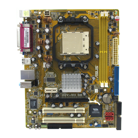
Page 16: Motherboard.overview
Motherboard overview 1.5.1 Motherboard layout 19.3cm (7.6in) PS/2KBMS T : Mouse B: Keyboard ATX12V USB34 CPU_FAN LAN1_USB12 W83124RG-A2 VIA K8M890 AUDIO SB_PWR PCIEX1_1 Attansic M2V-MX.SE CR2032 3V Lithium Cell PCIEX16 BIOS CMOS Power Super I/O PCI1 VIA VT8237S SATA2 USB56 SATA1 PCI2 ALC662... -
Page 17: Placement Direction
1.5.3. Screw.holes Place six (6) screws into the holes indicated by circles to secure the motherboard to the chassis. Do not overtighten the screws! Doing so can damage the motherboard. Place.this.side.towards. the.rear.of.the.chassis M2V-MX.SE ASUS M2V-MX SE... -
Page 18: Central.processing.unit.(Cpu)
Central Processing Unit (CPU) The motherboard comes with a 940-pin AM2 socket designed for the AMD Opetron /AMD Athlon™ 64 FX/Athlon™ 64 X2/AMD Athlon™ 64/AMD Sempron™ processor. Make sure you use a CPU is designed for the AM2 socket. The CPU fits in only one correct orientation. - Page 19 Connect the CPU fan cable to the CPU_FAN connector on the motherboard. CPU_FAN CPU FAN PWM CPU FAN IN CPU FAN PWR M2V-MX.SE M2V-MX.SE.CPU.Fan.Connector Do not forget to connect the CPU fan connector! Hardware monitoring errors can occur if you fail to plug this connector. ASUS M2V-MX SE...
-
Page 20: Installing The Heatsink And Fan
1.6.2. Installing.the.heatsink.and.fan The AMD Opetron™/AMD Athlon™ 64 FX/ AMD Athlon™ 64 X2/AMD Athlon™ 64/AMD Sempron™ processor require a specially designed heatsink and fan assembly to ensure optimum thermal condition and performance. Make sure that you use only qualified heatsink and fan assembly. Follow these steps to install the CPU heatsink and fan. - Page 21 Push down the retention bracket lock on the retention mechanism to secure the heatsink and fan to the module base. ASUS M2V-MX SE 1-11...
-
Page 22: System.memory
4 GB system memory when you installed two 2 GB DDR2 memory modules. • For optimum compatibility, we recommend that you obtain memory modules from the same vendor. Visit the ASUS website (www.asus.com) for the latest Qualified Vendors List. 1-12 Chapter 1: Product introduction... -
Page 23: Ddr2 Qualified Vendors List
DDR2 Qualified Vendors List The following table lists the memory modules that have been tested and qualified for use with this motherboard. Visit the ASUS website (www.asus.com) for the latest DDR2 DIMM modules for this motherboard. DDR2 533 Qualified Vendors List... - Page 24 DDR2 667 Qualified Vendors List DIMM support Size Vendor Model Side(s) Component 512MB ADATA M20EL5G3H3160B1C0Z E5108AE-6E-E • 513MB ADATA M20AD5G3H3166I1C52 AD29608A8A-3EG20648 • ADATA M2OAD5G3I4176I1C52 AD29608A8A-3EG20645 • 512MB AENEON AET660UD00-30DA98Z AET93F30DA 0552 • • 512MB AENEON AET660UD00-30DB97X AET93R300B 0634 • • 512MB AENEON AET660UD00-30DA98Z...
- Page 25 M2GVD5G3H31A4I1C52 VD29608A8A-3EC20615 • 512MB VDATA M2YVD5G3H31P4I1C52 VD29608A8A-3EG20627 • 512MB VDATA M2GVD5G3H166I1C52 VD29608A8A-3EG20637 • VDATA M2GVD5G3I41P6I1C52 VD29608A8A-3EG20627 • VDATA M2GVD5G3I41C4I1C52 VD29608A8A-3EC20620 • VDATA M2GVD5G3I4176I1C52 VD29608A8A-3EG20641 • 512MB VERITECH GTP512HLTM45EG VTD264M8PC6G01A164129621 • • VERITECH GTP01GHLTM55EG VTD264M8PC6G01A164129621 • • ASUS M2V-MX SE 1-15...
-
Page 26: Memory Configuration
A - supports one module inserted in any slot as Single-channel memory configuration B - supports one pair of modules inserted into either slots as one pair of Dual-channel memory configuration Visit the ASUS website (www.asus.com) for the latest memory Qualified Vendor List (QVL). 1-16... -
Page 27: Installing A Dimm
DIMM. Support the DIMM lightly with your fingers when pressing the retaining clips. The DIMM might DDR2 DIMM notch get damaged when it flips out with extra force. Remove the DIMM from the socket. ASUS M2V-MX SE 1-17... -
Page 28: Expansion.slots
Expansion slots In the future, you may need to install expansion cards. The following sub-sections describe the slots and the expansion cards that they support. Make sure to unplug the power cord before adding or removing expansion cards. Failure to do so may cause you physical injury and damage motherboard components. -
Page 29: Irq Assignments For This Motherboard
When using PCI cards on shared slots, ensure that the drivers support “Share IRQ” or that the cards do not need IRQ assignments; otherwise, conflicts will arise between the two PCI groups, making the system unstable and the card inoperable. ASUS M2V-MX SE 1-19... -
Page 30: Pci Slots
1.8.3. PCI.slots The PCI slots support cards such as a LAN card, SCSI card, USB card, and other cards that comply with PCI specifications. The figure shows a LAN card installed on a PCI slot. 1.8.4. PCI.Express.x1.slot This motherboard supports PCI Express x1 network cards, SCSI cards and other cards that comply with the PCI Express specifications. -
Page 31: Jumpers
Except when clearing the RTC RAM, never remove the cap on CLRTC jumper default position. Removing the cap will cause system boot failure! CLRTC M2V-MX.SE Normal Clear RTC (Default) M2V-MX SE Clear RTC RAM ASUS M2V-MX SE 1-21... - Page 32 USB device wake-up (3-pin PS2_USBPW1-4, USBPW5-8) Set these jumpers to +5V to wake up the computer from S1 sleep mode (CPU stopped, DRAM refreshed, system running in low power mode) using the connected USB devices. Set to +5VSB to wake up from S3 and S4 sleep modes (no power to CPU, DRAM in slow refresh, power supply in reduced power mode).
-
Page 33: 1.10 Connectors
2, 4, or 6-channel configuration. Audio 2, 4, or 6-channel configuration Port Headset 4-channel 6-channel 2-channel Light Blue Line In Surround (Rear) Surround (Rear) Green Line Out Front Speaker Out Front Speaker Out Pink Mic In Mic In Bass/Center ASUS M2V-MX SE 1-23... -
Page 34: Internal Connectors
Pin 5 on the connector is removed to prevent incorrect cable connection when using an FDD cable with a covered Pin 5. FLOPPY M2V-MX.SE NOTE: Orient the gray markings on the floppy ribbon cable to PIN 1. M2V-MX SE Floppy Disk Drive Connector 1-24 Chapter 1: Product introduction... -
Page 35: Ide Connectors
If any device jumper is set as “Cable-Select,” make sure all other device jumpers have the same setting. NOTE: Orient the gray markings (usually zigzag) on the ID ribbon cable to PIN 1. M2V-MX.SE IDE Connectors M2V-MX.SE. ASUS M2V-MX SE 1-25... - Page 36 Serial ATA connectors (7-pin SATA1[red], SATA2 [red]) These connectors are for the Serial ATA signal cables for Serial ATA hard disk and optical disk drives that allows 150 MB/s and 300MB/S data transfer rates, faster than the standard parallel ATA with 133 MB/s (Ultra DMA133). If you install Serial ATA hard disk drives, you can create a RAID 0, RAID 1, and JBOD configuration through the onboard VIA VT8237S...
- Page 37 Optical drive audio in connectors (4-pin CD) These connectors allow you to receive stereo audio input from sound sources such as a CD-ROM, TV tuner, or MPEG card. Right Audio Channel Ground Ground (black) Left Audio Channel M2V-MX.SE M2V-MX.SE.Internal.Audio Connector ASUS M2V-MX SE 1-27...
-
Page 38: Usb Connectors
USB connectors (10-1 pin USB56, USB78) These connectors are for USB 2.0 ports. Connect the USB module cable to any of these connectors, then install the module to a slot opening at the back of the system chassis. These USB connectors comply with USB 2.0 specification that supports up to 480 Mbps connection speed. - Page 39 +12 Volts +5 Volts +5V Standby Power OK -5 Volts Ground Ground +5 Volts Ground Ground Ground +5 Volts PSON# M2V-MX.SE Ground Ground +3 Volts -12 Volts +3 Volts +3 Volts M2V-MX SE uATX Power Connector ASUS M2V-MX SE 1-29...
-
Page 40: System Panel Connector
System.panel.connector.(10-1.pin.PANEL) This connector supports several chassis-mounted functions. PWR LED PWR BTN F_PANEL M2V-MX.SE +HDLED RESET System.Panel.Connector. M2V-MX.SE. System power LED (2-pin PWRLED) • This 2-pin connector is for the system power LED. Connect the chassis power LED cable to this connector. The system power LED lights up when you turn on the system power, and blinks when the system is in sleep mode. - Page 41 The S/PDIF out module is purchased separately. 11. Speaker connector (4-pin SPEAKER) This 4-pin connector is for the chasis-mounted system warning speaker. The speaker allows you to hear system beeps and warnings. SPEAKER M2V-MX.SE M2V-MX.SE.Speaker Out Connector ASUS M2V-MX SE 1-31...
- Page 42 1-32 Chapter 1: Product introduction...
-
Page 43: Chapter.2:.Bios Setup
This chapter tells how to change the system settings through the BIOS Setup menus. Detailed descriptions of the BIOS parameters are also provided. BIOS setup... -
Page 44: Managing And Updating Your Bios
The following utilities allow you to manage and update the motherboard Basic Input/Output System (BIOS) setup. ASUS.EZ.Flash (Updates the BIOS using a floppy disk, USB Flash, or the motherboard support CD during POST.) ASUS AFUDOS (Updates the BIOS in DOS mode using a bootable floppy disk.) -
Page 45: Asus Ez Flash Utility
2.1.2 ASUS EZ Flash utility The ASUS EZ Flash feature allows you to update the BIOS without having to go through the long process of booting from a floppy disk and using a DOS-based utility. The EZ Flash utility is built-in the BIOS chip so it is accessible by pressing <Alt>... -
Page 46: Afudos Utility
Insert the floppy disk that contains the BIOS file to the floppy disk drive. When the correct BIOS file is found, EZ Flash performs the BIOS update process and automatically reboots the system when done. EZFlash starting BIOS update Checking for floppy... Floppy found! Reading file “M2V_MX SE.rom”. -
Page 47: Updating The Bios File
Updating the BIOS file To update the BIOS file using the AFUDOS utility: Visit the ASUS website (www.asus.com) and download the latest BIOS file for the motherboard. Save the BIOS file to a bootable floppy disk. Write the BIOS filename on a piece of paper. You need to type the exact BIOS filename at the DOS prompt. -
Page 48: Asus Crashfree Bios 2 Utility
2.1.4 ASUS CrashFree BIOS 2 utility The ASUS CrashFree BIOS 2 is an auto recovery tool that allows you to restore the BIOS file when it fails or gets corrupted during the updating process. You can update a corrupted BIOS file using the motherboard support CD, or the floppy disk that contains the updated BIOS file. -
Page 49: Recovering The Bios From The Support Cd
Restart the system after the utility completes the updating process. The recovered BIOS may not be the latest BIOS version for this motherboard. Visit the ASUS website (www.asus.com) to download the latest BIOS file. ASUS M2V-MX SE... -
Page 50: Asus Update Utility
2.1.5 ASUS Update utility The ASUS Update is a utility that allows you to manage, save, and update the motherboard BIOS in Windows environment. The ASUS Update utility allows you ® • Save the current BIOS file • Download the latest BIOS file from the Internet •... - Page 51 Updating the BIOS through the Internet To update the BIOS through the Internet: desktop by clicking Start. Launch the ASUS Update utility from the Windows ® >.Programs.>.ASUS.>.ASUSUpdate.>.ASUSUpdate. The ASUS Update main window appears. Select Update.BIOS.from. Select the ASUS FTP site nearest the.Internet option from the...
- Page 52 Updating the BIOS through a BIOS file To update the BIOS through a BIOS file: desktop by clicking Start. Launch the ASUS Update utility from the Windows ® >.Programs.>.ASUS.>.ASUSUpdate.>.ASUSUpdate. The ASUS Update main window appears. Select Update BIOS from a file option from the drop-down menu, then click Next.
-
Page 53: Bios Setup Program
The BIOS setup screens shown in this section are for reference purposes only, and may not exactly match what you see on your screen. • Visit the ASUS website (www.asus.com) to download the latest BIOS file for this motherboard. ASUS M2V-MX SE... -
Page 54: Bios Menu Screen
2.2.1. BIOS menu screen Menu items Menu bar Configuration fields General.help Use [ENTER], [TAB] System Time [11:51:19] or [SHIFT-TAB] to System Date [Thu 07/12/2007] select a field. Legacy Diskette A [1.44M, 3.5 in] Use [+] or [-] to configure system time. Primary IDE Master : [ST320413A] Primary IDE Slave... -
Page 55: Menu Items
PageUp/PageDown keys to display the other items on the screen. 2.2.9. General.help (C)Copyright 1985-2007, American Megatrends, Inc. Pop-up window Scroll.bar At the top right corner of the menu screen is a brief description of the selected item. ASUS M2V-MX SE 2-13... -
Page 56: Main Menu
Main menu When you enter the BIOS Setup program, the Main menu screen appears, giving you an overview of the basic system information. Refer to section “2.2.1 BIOS menu screen” for information on the menu screen items and how to navigate through them. System Time [11:51:19] Use [ENTER], [TAB]... -
Page 57: Primary And Secondary Ide Master/Slave
When set to Disabled, the data transfer from and to the device occurs one sector at a time. Configuration options: [Disabled] [Auto] ASUS M2V-MX SE 2-15... - Page 58 PIO Mode [Auto] Selects the PIO mode. Configuration options: [Auto] [0] [1] [2] [3] [4] DMA Mode [Auto] Selects the DMA mode. Configuration options: [Auto] [SWDMA0] [SWDMA1] [SWDMA2] [MWDMA0] [MWDMA1] [MWDMA2] [UDMA0] [UDMA1] [UDMA2] [UDMA3] [UDMA4] [UDMA5] SMART Monitoring [Auto] Sets the Smart Monitoring, Analysis, and Reporting Technology.
-
Page 59: Sata1 And Sata2
When set to [Disabled], the data transfer from and to the device occurs one sector at a time. Configuration options: [Disabled] [Auto] PIO Mode [Auto] Selects the PIO mode. Configuration options: [Auto] [0] [1] [2] [3] [4] ASUS M2V-MX SE 2-17... -
Page 60: Ide Configuration
DMA Mode [Auto] Selects the DMA mode. Configuration options: [Auto] [SWDMA0] [SWDMA1] [SWDMA2] [MWDMA0] [MWDMA1] [MWDMA2] [UDMA0] [UDMA1] [UDMA2] [UDMA3] [UDMA4] [UDMA5] SMART Monitoring [Auto] Sets the Smart Monitoring, Analysis, and Reporting Technology. Configuration options: [Auto] [Disabled] [Enabled] 32Bit Data Transfer [Disabled] Enables or disables 32-bit data transfer. -
Page 61: System Information
: AMD Sempron(tm) Processor 3200+ Speed : 1800MHz Count System Memory Installed Size: 512MB Usable Size : 348MB AMI.BIOS Displays the auto-detected BIOS information. Processor Displays the auto-detected processor information. System.Memory Displays the auto-detected system memory. ASUS M2V-MX SE 2-19... -
Page 62: Advanced Menu
Advanced menu The Advanced menu items allow you to change the settings for the CPU and other system devices. Take caution when changing the settings of the Advanced menu items. Incorrect field values can cause the system to malfunction. USB Configuration CPU Configuration Chipset Onboard Devices Configuration... - Page 63 Allows you to configure the USB 2.0 controller in HiSpeed (480 Mbps) or Full Speed (12 Mbps). Configuration options: [HiSpeed] [Full Speed] BIOS EHCI Hand-Off [Enabled] Allows you to enable or disable the BIOS EHCI hand-off support. Configuration options: [Disabled] [Enabled] ASUS M2V-MX SE 2-21...
-
Page 64: Cpu Configuration
2.4.2 CPU Configuration The items in this menu show the CPU-related information that the BIOS automatically detects. CPU Configuration Module Version:13.13 AGESA Version:02.08.07 Physical Count: 1 Logical Count: 1 AMD Sempron(tm) Processor 3200+ Revision: F2 Cache L1: 64KB Cache L2: 128KB Speed : 1800MHz Current FSB Multiplier: 9x... -
Page 65: Chipset
Allows you to set the memory clock mode.Set by the code using [Auto] or select [Manual] to set using one of the standard values. Configuration options: [Auto] [Manual] [Limit] CAS Latency (CL) [Auto] Configuration options: [Auto] [3.0] [4.0] [5.0] [6.0] ASUS M2V-MX SE 2-23... - Page 66 TRCD [Auto] Configuration options: [Auto] [3 CLK] [4 CLK] [5 CLK] [6 CLK] TRP [Auto] Configuration options: [Auto] [3 CLK] [4 CLK] [5 CLK] [6 CLK] TRAS [Auto] Configuration options: [Auto] [5 CLK] [6 CLK] ... [18 CLK] Command Timing 2T Mode [Auto] Sets the 2T mode.
- Page 67 [640ns] [1.28us] [2.56us] [5.12us] [10.2us] [20.5us] [41.0us] [81.9us] [163.8us] [327.7us] [655.4us] Power Down Control [Auto] Allows DIMMs to enter power down mode by deasserting the clock enable signal when DIMMs are not in use. Configuration options: [Auto] [Disabled] ASUS M2V-MX SE 2-25...
- Page 68 AGP Bridge K8M890 AGP/PCI EXPRESS Configuration OnChip VGA Frame Buffer Size [64MB] Options for VIA AGP Primary Graphics Adapter [PCIE VGA] Chipset VLink Mode Supported [Auto] AGP Mode [AGP 8X] Graphics Aperture Size [128MB] OnChip VGA Frame Buffer Size [128MB] Sets the onchip VGA frame buffer size.
-
Page 69: Hyper Transport Configuration
Hyper Transport Configuration Hyper Transport AGP Configuration (K8/NPT) to (AGP) Freq Auto [Enabled] (K8/NPT) to (AGP) Freq Auto [Enabled] Allows you to enable or disable the K8/NPT to AGP frequency selection by CPU capability. Configuration options: [Enabled] [Disabled] ASUS M2V-MX SE 2-27... -
Page 70: Onboard Devices Configuration
2.4.4 Onboard Devices Configuration Congifure ITE8712F-S/KX-L Super IO Chipset Serial Port Address [3F8/IRQ4] Parallel Port Address [378] Parallel Port Mode [Normal] Parallel Port IRQ [IRQ7] Serial Port Address [3F8/IRQ4] Allows you to select the Serial Port1 base address. Configuration options: [Disabled] [3F8/IRQ4] [2E8/IRQ3][3E8/IRQ4] [2E8/IRQ3] Parallel Port Address [378] Allows you to select the Parallel Port base addresses. -
Page 71: Pci Pnp
Setting to [Disabled] deactivates this feature. Configuration options: [Disabled] [Enabled] IRQ xx [Available] When set to [Available], the specific IRQ is free for PCI/PnP devices to use. When set to [Reserved], the IRQ is reserved for legacy ISA devices. Configuration options: [Available] [Reserved] ASUS M2V-MX SE 2-29... -
Page 72: Power Menu
Power menu The Power menu items allow you to change the settings for the Advanced Power Management (APM) feature. Select an item then press <Enter> to display the configuration options. Select the ACPI state Suspend Mode [Auto] used for System ACPI Version Support [ACPI v2.0] Suspend. -
Page 73: Apm Configuration
When set to [Enabled], this parameter allows you to turn on the system through a PCI LAN or modem card. This feature requires an ATX power supply that provides at least 1A on the +5VSB lead. Configuration options: [Disabled] [Enabled] ASUS M2V-MX SE 2-31... - Page 74 Power On By PME [Disabled] When this item is set to [Enabled]. A PME (Power Management Event) can turn on the system. Configuration Options: [Disabled] [Enabled] Power On By KBC [Disabled] Allows you to use specific keys on the keyboard to turn on the system. This feature requires an ATX power supply that provides at least 1A on the +5VSB lead.
-
Page 75: Hardware Monitor
Allows you to enable or disable the smart Q-fan control function. When this field is set to [Enabled], the item Fan Auto Mode.items.appear. Configuration options: [Disabled] [Enabled] Fan Auto Mode Start Voltage, Start Speed Temp, Full Speed Temp Sets the smart fan mode. ASUS M2V-MX SE 2-33... -
Page 76: Boot Menu
Boot menu The Boot menu items allow you to change the system boot options. Select an item then press <Enter> to display the sub-menu. Specifies the Boot Boot Settings Device Priority sequence. Boot Device Priority Boot Settings Configuration Security 2.6.1 Boot Device Priority Specifies the boot Boot Device Priority... -
Page 77: Boot Settings Configuration
Full Screen Logo [Enabled] Allows you to enable or disable the full screen logo display feature. Configuration options: [Disabled] [Enabled] Make sure that the above item is set to [Enabled] if you want to use the ASUS MyLogo™ feature. Bootup Num-Lock [On] Allows you to select the power-on state for the NumLock. -
Page 78: Security
2.6.3 Security The Security menu items allow you to change the system security settings. Select an item then press <Enter>.to display the configuration options. <Enter> to change Security Settings password. <Enter> again to Supervisor Password : Not Installed disable password. User Password : Not Installed Change Supervisor Password... - Page 79 2. On the password box that appears, type a password combination of at least six (6) letters and/or numbers, then press <Enter>. 3. Confirm the password when prompted. The message “Password Installed” appears after you have successfully set your password. The User Password item now shows Installed. ASUS M2V-MX SE 2-37...
- Page 80 After you have set a supervisor password, the other items appear to allow you to change other security settings. Security Settings Supervisor Password : Not Installed User Password : Not Installed Change Supervisor Password User Access Level [Full Access] Change User Password Password Check [Setup] Select Screen...
-
Page 81: Exit Menu
Select this option only if you do not want to save the changes that you made to the Setup program. If you made changes to fields other than System Date, System Time, and Password, the BIOS asks for a confirmation before exiting. ASUS M2V-MX SE 2-39... -
Page 82: Discard Changes
Discard Changes Allows you to discard the selections you made and restore the previously saved values. After selecting this option, a confirmation appears. Select Yes to discard any changes and load the previously saved values. Load Setup Defaults This option allows you to load the default values for each of the parameters on the Setup menus. -
Page 83: Chapter.3:.Software Support
This chapter describes the contents of the support CD that comes with the motherboard package. Software support... -
Page 84: Installing.an.operating.system
The contents of the support CD are subject to change at any time without notice. Visit the ASUS website (www.asus.com) for updates. 3.2.1 Running the support CD Place the support CD to the optical drive. -
Page 85: Drivers Menu
The drivers menu shows the available device drivers if the system detects installed devices. Install the necessary drivers to activate the devices. ASUS InstAll-Drivers Installation Wizard Installs the ASUS InstAll-Drivers Installation Wizard. AMD Cool ‘n’ Quiet Driver Installs the AMD Cool ‘n’ Quiet driver. -
Page 86: Utilities Menu
This utility helps you keep your computer in healthy operating condition. ASUS.Update. The ASUS Update utility allows you to update the motherboard BIOS in a Windows environment. This utility requires an Internet connection either through a ®... - Page 87 Install the following utilities from the ASUS Superb Software Library CD if needed.. ADOBE Acrobat Reader V7.0 Installs the Adobe Acrobat Reader that allows you to open, view, and ® ® print documents in Portable Document Format (PDF). Microsoft DirectX 9.0c Installs the Microsoft DirectX 9.0c driver.
-
Page 88: Make Disk Menu
3.2.4 Make Disk menu The Make Disk menu allows you to make a RAID driver disk. VIA 32/64 bit RAID Driver Allows you to create a VIA 32/64 bit RAID driver disk. ® Chapter 3: Software support... -
Page 89: Manual Menu
Realtek HD Audio User’s Manual Allows you to open Realtek HD Audio user’s manual. The user manual files are in Portable Document Format (PDF). Install the Adobe Acrobat Reader application from the Utilities tab before opening a user manual file. ASUS M2V-MX SE... -
Page 90: Asus Contact Information
3.2.6. ASUS.Contact.information Click the Contact tab to display the ASUS contact information. You can also find this information on the inside front cover of this user guide. Chapter 3: Software support...