Table of Contents
Advertisement
Advertisement
Table of Contents

Related Manuals for Asus M2V-TVM


Summary of Contents for Asus M2V-TVM
- Page 1 M2V-TVM...
- Page 2 Product warranty or service will not be extended if: (1) the product is repaired, modified or altered, unless such repair, modification of alteration is authorized in writing by ASUS; or (2) the serial number of the product is defaced or missing.
-
Page 3: Table Of Contents
Contents Notices ... vi Safety information ...vii M2V-TVM specifications summary ...viii Chapter 1: Product introduction Welcome! ... 1-2 Package contents ... 1-2 Special features ... 1-2 1.3.1 Product highlights ... 1-2 1.3.2 Innovative ASUS features ... 1-4 Before you proceed ... 1-5 Motherboard overview ... - Page 4 Using AFUDOS to update the BIOS ... 2-3 2.1.3 Using AFUDOS to copy BIOS from PC ... 2-4 2.1.4 Using ASUS EZ Flash to update the BIOS ... 2-5 2.1.5 ASUS Update ... 2-7 BIOS setup program ... 2-9 2.2.1 BIOS menu screen ...
- Page 5 Installing an operating system ... 3-2 Support CD information ... 3-2 3.2.1 Running the support CD ... 3-2 3.2.2 Drivers menu ... 3-3 3.2.3 Utilities menu ... 3-4 3.2.4 Make Disk menu ... 3-5 3.2.5 ASUS Contact information ... 3-6...
-
Page 6: Notices
Notices Federal Communications Commission Statement This device complies with Part 15 of the FCC Rules. Operation is subject to the following two conditions: • This device may not cause harmful interference, and • This device must accept any interference received including interference that may cause undesired operation. -
Page 7: Safety Information
Safety information Electrical safety • To prevent electrical shock hazard, disconnect the power cable from the electrical outlet before relocating the system. • When adding or removing devices to or from the system, ensure that the power cables for the devices are unplugged before the signal cables are connected. -
Page 8: M2V-Tvm Specifications Summary
M2V-TVM specifications summary Chipset System Bus Memory Expansion slots Graphics Storage Audio USB 2.0 Special features Backpanel I/O ports viii Support AMD socket AM2 for AMD Athlon™ 64 X2/ Athlon™ 64/AMD Sempron™ processor AMD64 architecture enables simultaneous 32-bit and 64-bit computing Supports AMD Cool ‘n’... - Page 9 M2V-TVM specifications summary 2 x USB connector supports additional 4 USB ports Internal I/O connectors 24-pin ATX power connector 4-pin ATX 12V power connector 1 x COM connector 1 x S/PDIF out connector 1 x CD audio-in connector 1 x AUX audio-in connector 1 x CPU/ 1 x Chassis fan connectors 1 x Front Panel AC’97 audio connector...
-
Page 11: Chapter 1: Product Introduction
This chapter describes the motherboard features and the new technologies it supports. Product introduction... -
Page 12: Welcome
Thank you for buying an ASUS The motherboard delivers a host of new features and latest technologies, making it another standout in the long line of ASUS quality motherboards! Before you start installing the motherboard, and hardware devices on it, check the items in your package with the list below. - Page 13 USB 1.1. See pages 1-21 and 1-6 for details. 10/100 Mbps LAN Easy connectivity to your network or broadband connection with the onboard LAN port, lets you take gaming online without buying expensive additional LAN cards. ASUS M2V-TVM...
-
Page 14: Innovative Asus Features
See page 2-5 for details. ASUS MyLogo 2 ASUS My Logo 2 is the new feature present in the motherboard that allows you to personalize and add style to your system with customizable and animated boot logos. See page 2-30 for details. -
Page 15: Before You Proceed
This is a reminder that you should shut down the system and unplug the power cable before removing or plugging in any motherboard component. The illustration below shows the location of the onboard LED. M2V-TVM M2V-TVM Onboard LED connector ASUS M2V-TVM SB_PWR Standy Powered... -
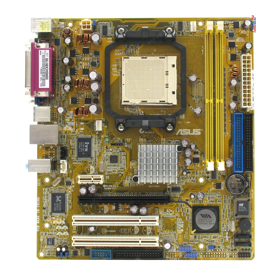
Page 16: Motherboard Overview
ATX12V PS2/2KBMS T:Mouse B:Keyboard USB12 CHA_FAN LAN_USB34 IT8716F-S AUDIO2 PCIEX1_1 PCIEX16 RTL8100C PCI1 PCI2 ALC655 AAFP KBPWR M2V-TVM SB_PWR COM2 LOPPY USB56 Chapter 1: Product introduction CPU_FAN EATXPWR CR2032 3V Lithium Cell CMOS Power BIOS BUZZER SATA2 SATA1 CLRTC F_PANEL... -
Page 17: Placement Direction
Place six (6) screws into the holes indicated by circles to secure the motherboard to the chassis. Do not overtighten the screws! Doing so can damage the motherboard. Place this side towards the rear of the chassis ASUS M2V-TVM M2V-TVM... -
Page 18: Central Processing Unit (Cpu)
CPU! 1.6.1 Installing the CPU To install a CPU. Locate the CPU socket on the motherboard. M2V-TVM CPU Socket AM2 Unlock the socket by pressing the lever sideways, then lift it up to a 90°-100° angle. - Page 19 Connect the CPU fan cable to the CPU_FAN connector on the motherboard. M2V-TVM M2V-TVM CPU Fan connector Do not forget to connect the CPU fan connector! Hardware monitoring errors can occur if you fail to plug this connector. ASUS M2V-TVM...
-
Page 20: Installing The Heatsink And Fan
1.6.2 Installing the heatsink and fan The AMD Athlon™ 64 X2/AMD Athlon™ 64/AMD Sempron™ processor require a specially designed heatsink and fan assembly to ensure optimum thermal condition and performance. Make sure that you use only qualified heatsink and fan assembly. Follow these steps to install the CPU heatsink and fan. - Page 21 Push down the retention bracket lock on the retention mechanism to secure the heatsink and fan to the module base. ASUS M2V-TVM 1-11...
-
Page 22: System Memory
You may install 256 MB, 512 MB, and 1 GB unbuffered non-ECC DDR2 DIMMs into the DIMM sockets. For optimum compatibility, we recommend that you obtain memory modules from the same vendor. Visit the ASUS website (www.asus.com) for the latest Qualified Vendors List.. 1-12... - Page 23 MIII0052532M8CEC HY5PS12821AFP-Y4 Kingmax KKEA88B4IAK-37 Kingmax E5116AB-5C-E Kingmax E5108AE-6E-E VDATA VD29608A8A-3EC20615 VDATA VD29608A8A-3EC20620 Side(s): SS - Single-sided Visit the ASUS website for the latest DDR2-667/533 MHz QVL. ASUS M2V-TVM Chip Number Size 256MB 256MB 512MB 256MB 512MB 512MB 512MB 512MB 512MB...
-
Page 24: Installing A Dimm
1.7.3 Installing a DIMM Unplug the power supply before adding or removing DIMMs or other system components. Failure to do so can cause severe damage to both the motherboard and the components. To install a DIMM: Unlock a DIMM socket by pressing the retaining clips outward. -
Page 25: Expansion Slots
Turn on the system and change the necessary BIOS settings, if any. See Chapter 2 for information on BIOS setup. Assign an IRQ to the card. Refer to the tables on the next page. Install the software drivers for the expansion card. ASUS M2V-TVM 1-15... -
Page 26: Standard Interrupt Assignments
Standard interrupt assignments Priority – * These IRQs are usually available for ISA or PCI devices. IRQ assignments for this motherboard PCI slot 1 PCI slot 2 When using PCI cards on shared slots, ensure that the drivers support “Share IRQ” or that the cards do not need IRQ assignments; otherwise, conflicts will arise between the two PCI groups, making the system unstable and the card inoperable. -
Page 27: Pci Slots
PCI Express x1 slot. 1.8.5 PCI Express x16 slot This motherboard has supports PCI Express x16 graphic cards that comply with PCI Express specifications. The figure shows a graphics card installed on the PCI Express x16 slot. ASUS M2V-TVM 1-17... -
Page 28: Clear Rtc Ram
Hold down the <Del> key during the boot process and enter BIOS setup to re-enter data. Except when clearing the RTC RAM, never remove the cap on CLRTC jumper default position. Removing the cap will cause system boot failure! M2V-TVM Clear RTC RAM 1-18 M2V-TVM CLRTC... - Page 29 (the default is the Space Bar). This feature requires an ATX power supply that can supply at least 500 mA on the +5VSB lead, and a corresponding setting in the BIOS. M2V-TVM M2V-TVM Fan connectors ASUS M2V-TVM KBPWR +5VSB...
-
Page 30: 1.10 Connectors
1.10 Connectors 1.10.1 Rear panel connectors PS/2 mouse port (green). This port is for a PS/2 mouse. Parallel port. This 25-pin port connects a printer, scanner, or other devices. LAN (RJ-45) port. This port allows Gigabit connection to a Local Area Network (LAN) through a network hub. -
Page 31: 1.10.2 Internal Connectors
Pin 5 on the connector is removed to prevent incorrect cable connection when using an FDD cable with a covered Pin 5. M2V-TVM M2V-TVM Floppy disk drive consnector ASUS M2V-TVM FLOPPY NOTE:Orient the red markings on the floppy ribbon cable to PIN1. - Page 32 • Use the 80-conductor IDE cable for Ultra DMA 133/100/66 IDE devices. If any device jumper is set as “Cable-Select,” make sure all other device jumpers have the same setting. M2V-TVM IDE connectors 1-22 Drive jumper Mode setting of device(s)
- Page 33 If you install Serial ATA hard disk drives, you can create a RAID 0, RAID 1, and JBOD configuration through the onboard VIA Plus controller. M2V-TVM M2V-TVM SATA connectors Important note on Serial ATA Install the Windows Pack1 before using Serial ATA.
- Page 34 Do not forget to connect the fan cables to the fan connectors. Insufficient air flow inside the system may damage the motherboard components. These are not jumpers! DO NOT place jumper caps on the fan connectors. M2V-TVM Fan connectors 1-24 CPU_FAN CPU FAN PWM...
- Page 35 The serial port bracket (COM) is purchased separately. M2V-TVM M2V-TVM COM port connector Optical drive audio in connectors (4-pin CD/AUX) These connectors allow you to receive stereo audio input from sound sources such as a CD-ROM, TV tuner, or MPEG card.
- Page 36 These USB connectors comply with USB 2.0 specification that supports up to 480 Mbps connection speed. M2V-TVM USB connectors Never connect a 1394 cable to the USB connectors. Doing so will damage the motherboard! The USB 2.0 module is purchased separately.
- Page 37 This connector is for a chassis-mounted front panel audio I/O module that supports the AC`97 audio standard. Connect one end of the front panel audio I/O module cable to this connector. M2V-TVM AAFP M2V-TVM Analog front panel connector ASUS M2V-TVM 1-27...
- Page 38 • You must install a PSU with a higher power rating if you intend to install additional devices. M2V-TVM ATX power connectors 1-28 ATX12V +12V DC EATXPWR...
-
Page 39: System Panel Connector
10. System panel connector (2x5 10 pin F_PANEL) This connector supports several chassis-mounted functions. M2V-TVM M2V-TVM System panel connector • System power LED This 3-pin connector is for the system power LED. Connect the chassis power LED cable to this connector. The system power LED lights up when you turn on the system power, and blinks when the system is in sleep mode. - Page 40 1-30 Chapter 1: Product introduction...
-
Page 41: Chapter 2: Bios Setup
This chapter tells how to change the system settings through the BIOS Setup menus. Detailed descriptions of the BIOS parameters are also provided. BIOS setup ASUS M2V-TVM... -
Page 42: Managing And Updating Your Bios
The following utilities allow you to manage and update the motherboard Basic Input/Output System (BIOS) setup. 1. ASUS AFUDOS - Updates the BIOS using a bootable floppy disk in DOS mode. 2. ASUS EZ Flash - Updates the BIOS using a floppy disk during POST. -
Page 43: Using Afudos To Update The Bios
Using AFUDOS to update the BIOS To update the BIOS using the AFUDOS.EXE utility: 1. Visit the ASUS website to download the latest BIOS file for your motherboard. Save the BIOS file to a bootable floppy disk. Write the BIOS file name on a piece of paper. You need to type the exact BIOS file name at the prompt. -
Page 44: Using Afudos To Copy Bios From Pc
When the BIOS update process is complete, the utility returns to the DOS prompt. A:\>afudos /iM2VTVM.ROM AMI Firmware Update Utility - Version 1.10 Copyright (C) 2002 American Megatrends, Inc. All rights reserved. Reading file ... done Erasing flash ... done Writing flash ... 0x0008CC00 (9%) Verifying flash .. done A:\> 6. Reboot the system from the hard disk. 2.1.3 Using AFUDOS to copy BIOS from PC You can use the AFUDOS.EXE utility to copy the current system BIOS to a... -
Page 45: Using Asus Ez Flash To Update The Bios
2.1.4 Using ASUS EZ Flash to update the BIOS The ASUS EZ Flash feature allows you to easily update the BIOS without having to go through the long process of booting from a diskette and using a DOS-based utility. The EZ Flash is built-in to the BIOS firmware so it is accessible by simply pressing <Alt + F2> during the Power-On Self Tests (POST). - Page 46 4. Insert the floppy disk that contains the BIOS file. If all the necessary files are found in the floppy disk, EZ Flash performs the BIOS update process and automatically reboots the system when done. DO NOT shut down or reset the system while updating the BIOS! Doing so can cause system boot failure! User recovery requested.
-
Page 47: Asus Update
2.1.5 ASUS Update The ASUS Update is a utility that allows you to update the motherboard BIOS in Windows environment. This utility is available in the support ® CD that comes with the motherboard package. ASUS Update requires an Internet connection either through a network or an Internet Service Provider (ISP). - Page 48 If you select updating/ downloading from the Internet, select the ASUS FTP site nearest you to avoid network traffic, or choose Auto Select. Click Next. From the FTP site, select the BIOS version that you wish to download. Click Next.
-
Page 49: Bios Setup Program
The BIOS setup screens shown in this section are for reference purposes only, and may not exactly match what you see on your screen. • Visit the ASUS website (www.asus.com) to download the latest BIOS file for this motherboard. ASUS M2V-TVM... -
Page 50: Bios Menu Screen
2.2.1 BIOS menu screen Menu items Menu bar System Time System Date Legacy Diskette A Primary IDE Master : [Not Detected] Primary IDE Slave : [Not Detected] Secondary IDE Master : [Not Detected] Secondary IDE Slave : [Not Detected] Third IDE Master Fourth IDE Master IDE Configuration System Information Sub-menu items 2.2.2 Menu bar The menu bar on top of the screen has the following main items: Main For changing the basic system configuration Advanced For changing the advanced system settings Power... -
Page 51: Menu Items
2.2.9 General help At the top right corner of the menu screen is a brief description of the selected item. ASUS M2V-TVM System Time [11:10:19] Use [ENTER], [TAB] System Date [Thu 03/27/2003]... -
Page 52: Main Menu
Main menu When you enter the BIOS Setup program, the Main menu screen appears, giving you an overview of the basic system information. Refer to section “2.2.1 BIOS menu screen” for information on the menu screen items and how to navigate through them. System Time System Date Legacy Diskette A... -
Page 53: Primary And Secondary Ide Master/Slave
When set to Disabled, the data transfer from and to the device occurs one sector at a time. Configuration options: [Disabled] [Auto] ASUS M2V-TVM Select the type of device connected to the system... -
Page 54: System Information
PIO Mode [Auto] Selects the PIO mode. Configuration options: [Auto] [0] [1] [2] [3] [4] DMA Mode [Auto] Selects the DMA mode. Configuration options: [Auto] [SWDMA0] [SWDMA1] [SWDMA2] [MWDMA0] [MWDMA1] [MWDMA2] [UDMA0] [UDMA1] [UDMA2] [UDMA3] [UDMA4] [UDMA5] SMART Monitoring [Auto] Sets the Smart Monitoring, Analysis, and Reporting Technology. -
Page 55: Advanced Menu
Configuration options: [Disabled] [USB 2 Ports] [USB 4 Ports] [USB 6 Ports] [USB 8 Ports] USB 2.0 Ports Enable [Enable] Allows you to enable or disable the USB 2.0 ports. Configuration options: [Disabled] [Enable] ASUS M2V-TVM [USB 8 Ports] [Enable] [Enabled] [Disabled]... -
Page 56: Cpu Configuration
Legacy USB Support [Enabled] Allows you to enable or disable support for USB devices on legacy operating systems (OS). Setting to Auto allows the system to detect the presence of USB devices at startup. If detected, the USB controller legacy mode is enabled. -
Page 57: Chipset
Memory Hole Remapping Memclock Mode [Auto] Allows you to set the memory clock mode.Set by the code using [Auto] or select [Manual] to set using one of the standard values. Configuration options: [Auto] [Manual] [Limit] ASUS M2V-TVM [Auto] [0.850V] :333 MHz :5.0 :5 CLK... - Page 58 MCT Timing Mode [Auto] Appears only when the Parallel Port Mode is set to [ECP]. This item allows you to set the Parallel Port ECP DMA. Configuration options: [DMA0] [DMA1] [DMA3] Bank Interleacving [Auto] Sets whether to allow memory accesses to be spread out over BANKS on the same node or across nodes, decreasing access contention.
- Page 59 Allows DIMMs to enter power down mode by deasserting the clock enable signal when DIMMs are not in use. Configuration options: [Auto] [Disabled] Alternate VID [0.850V] Specifies the alternate VID while in low power states. Configuration options: [1.050V] [1.025V] [1.000V] [0.975V] [0.950V] [0.925V] [0.900V] [0.875V] [0.850V] [0.825V] [0.800V] ASUS M2V-TVM 2-19...
- Page 60 AGP Bridge K8M890 AGP/PCI EXPRESS Configuration OnChip VGA Frame Buffer Size Primary Graphics Adapter VLink Mode Supported AGP Mode Graphics Aperture Size OnChip VGA Frame Buffer Size [64MB] Sets the onchip VGA frame buffer size. Configuration options: [64MB] [128MB] [256MB] Primary Graphics Adapter [PCIE VGA] Switches the PCI Bus scanning order while searching for a video card. This allows you to select the type of Primary VGA in case of multiple video controllers.
-
Page 61: Onboard Devices Configuration
Allows you to select the Serial Port1 base address. Configuration options: [Disabled] [2F8/IRQ3] [3E8/IRQ4] [2E8/IRQ3] Serial Port2 Mode [Normal] Allows you to select the Serial Port2 mode. Configuration options: [Normal] [IrDA] [ASK IR] ASUS M2V-TVM [Enabled] [3F8/IRQ4] [Normal] [2F8/IRQ3] [Normal]... - Page 62 Parallel Port Address [378] Allows you to select the Parallel Port base addresses. Configuration options: [Disabled] [378] [278] [3BC] Parallel Port Mode [Normal] Allows you to select the Parallel Port mode. Configuration options: [Normal] [EPP] [ECP] [EPP+ECP] ECP Mode DMA Channel [DMA3] Allows you to select the Parallel Port ECP DMA.
-
Page 63: Pci Pnp
When set to [Yes], BIOS assigns an IRQ to PCI VGA card if the card requests for an IRQ. When set to [No], BIOS does not assign an IRQ to the PCI VGA card even if requested. Configuration options: [Yes] [No] ASUS M2V-TVM NO: Lets the BIOS configure all the devices in the system. - Page 64 Palette Snooping [Disabled] When set to [Enabled], the pallete snooping feature informs the PCI devices that an ISA graphics device is installed in the system so that the latter can function correctly. Setting to [Disabled] deactivates this feature. Configuration options: [Disabled] [Enabled] IRQ xx [Available] When set to [Available], the specific IRQ is free for PCI/PnP devices to use.
-
Page 65: Power Menu
ACPI APIC Support [Enabled] Enables or disables the ACPI support in the ASIC. When set to Enabled, the ACPI APIC table pointer is included in the RSDT pointer list. Configuration options: [Disabled] [Enabled] ASUS M2V-TVM Select the ACPI state [Auto] used for System [Enabled] Suspend. -
Page 66: Apm Configuration
2.5.3 APM Configuration APM Configuration Power Button Mode Restore on AC Power Loss Power On Ring Power On PME# Power On By KBC Power On By PS/2 Mouse Power On By RTC Alarm Power Button Mode [On/Off] Allows the system to go into On/Off mode or suspend mode when the power button is pressed. Configuration options: [On/Off] [Suspend] Restore on AC Power Loss [Power Off ] When set to Power Off, the system goes into off state after an AC power loss. -
Page 67: Hardware Monitor
ATX power supply that provides at least 1A on the +5VSB lead. Configuration options: [Disabled] [Enabled] 2.5.4 Hardware Monitor Hardware Monitor CPU Temperature MB Temperature CPU Fan Speed Chassis Fan Speed VCORE Voltage 3.3V Voltage 5V Voltage 12V Voltage Smart Q-Fan Function CPU temperature beep function [Enabled] CPU temperature high limit ASUS M2V-TVM CPU Temperature [48ºC/118ºF] [35ºC/95ºF] [3260RPM] [N/A] [ 1.504V] [ 3.360V] [ 5.160V] [11.328V] [Disabled] [95 degree] 2-27... - Page 68 CPU Temperature [xxx ºC/xxx ºF] MB Temperature [xxx ºC/xxx ºF] The onboard hardware monitor automatically detects and displays the CPU, motherboard and power temperatures. Select Disabled if you do not wish to display the detected temperatures. CPU Fan Speed [xxxxRPM] or [N/A] Chassis Fan Speed [xxxxRPM] or [N/A] The onboard hardware monitor automatically detects and displays the CPU and chassis fan speeds in rotations per minute (RPM).
-
Page 69: Boot Menu
These items specify the boot device priority sequence from the available devices. The number of device items that appear on the screen depends on the the number of devices installed in the system. Configuration options: [xxxxx Drive] [Disabled] ASUS M2V-TVM Specifies the Boot Device Priority sequence. -
Page 70: Boot Settings Configuration
Allows you to enable or disable the full screen logo display feature. Configuration options: [Disabled] [Enabled] Make sure that the above item is set to [Enabled] if you want to use the ASUS MyLogo2™ feature. Add On ROM Display Mode [Force BIOS] Sets the display mode for option ROM. -
Page 71: Security
The message “Password Installed” appears after you have successfully set your password. The Supervisor Password item now shows Installed. To change the supervisor password, follow the same steps as in setting a user password. ASUS M2V-TVM <Enter> to change password. <Enter> again to disable password. - Page 72 To clear the supervisor password, select the Change Supervisor Password then press <Enter>. The message “Password Uninstalled” appears. If you forget your BIOS password, you can clear clear it by erasing the CMOS Real Time Clock (RTC) RAM. See section “2.6 Jumpers” for information on how to erase the RTC RAM.
-
Page 73: Change User Password
Change User Password Select this item to set or change the user password. The User Password item on top of the screen shows the default Not Installed. After you set a password, this item shows Installed. ASUS M2V-TVM [Full Access] [Setup] Select Screen... - Page 74 To set a User Password: Select the Change User Password item and press <Enter>. On the password box that appears, type a password composed of at least six letters and/or numbers, then press <Enter>. Confirm the password when prompted. The message “Password Installed” appears after you set your password successfully.
-
Page 75: Exit Menu
Select this option only if you do not want to save the changes that you made to the Setup program. If you made changes to fields other than System Date, System Time, and Password, the BIOS asks for a confirmation before exiting. ASUS M2V-TVM Exit system setup after saving the changes. -
Page 76: Discard Changes
Discard Changes Allows you to discard the selections you made and restore the previously saved values. After selecting this option, a confirmation appears. Select Yes to discard any changes and load the previously saved values. Load Setup Defaults This option allows you to load the default values for each of the parameters on the Setup menus. -
Page 77: Chapter 3: Software Support
This chapter describes the contents of the support CD that comes with the motherboard package. Software support... -
Page 78: Installing An Operating System
The contents of the support CD are subject to change at any time without notice. Visit the ASUS website(www.asus.com) for updates. 3.2.1 Running the support CD Place the support CD to the optical drive. -
Page 79: Drivers Menu
Installs the VIA S3G display driver. Realtek Audio Driver Installs the Realtek audio driver. ® Realtek RTL8100C LAN Driver Installs the Realtek RTL8100C LAN driver. ® The screen display and drivers option may not be the same for different operating system versions. ASUS M2V-TVM... -
Page 80: Utilities Menu
ASUS Cool ‘n’ Quiet Utility Installs the ASUS Cool ‘n’ Quiet utility. ASUS Update The ASUS Update utility allows you to update the motherboard BIOS in a Windows environment. This utility requires an Internet connection either ® through a network or an Internet Service Provider (ISP). -
Page 81: Make Disk Menu
The anti-virus utility scans, identifies, and removes computer viruses. View the online help for detailed information. ASUS Screen Saver Installs the ASUS screen saver. The screen display and utilities option may not be the same for different operating system versions. -
Page 82: Asus Contact Information
3.2.5 ASUS Contact information Click the Contact tab to display the ASUS contact information. You can also find this information on the inside front cover of this user guide. Chapter 3: Software support...