Table of Contents
Advertisement
Introduction.................................................................................................................................................1
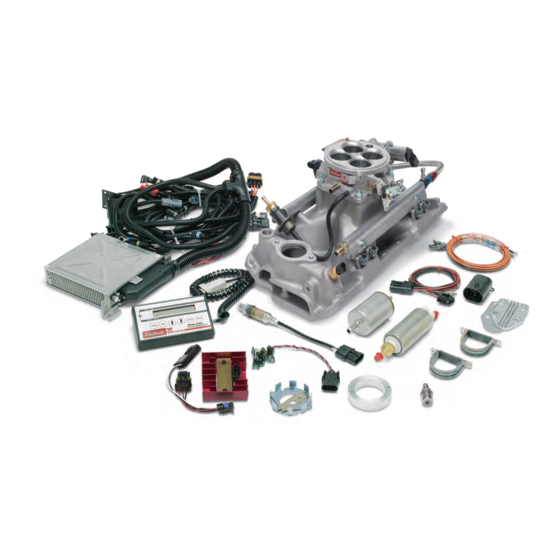
Components................................................................................................................................................2
Preliminaries ...........................................................................................................................................3-5
Fuel System ............................................................................................................................................6-9
Induction System.................................................................................................................................10-12
Sensors ...............................................................................................................................................13-15
Sensor Installation................................................................................................................................15
2
Main System Harness..........................................................................................................................16-20
Ignition System................................................................................................................................... 21-25
Other Applications .................................................................................................................................... 26
System Start-Up ..................................................................................................................................26-29
Electronic Engine Management .................................................................................................................30
Pro-Flo Quick Tuning Guide.......................................................................................................................31
Calibration Module Flowchart....................................................................................................................32
Parts and Part Numbers.......................................................................................................................33-34
Service & Warranty ...................................................................................................................................35
Thank you for selecting the Edelbrock Pro-Flo Fuel Injection System. This Multi-Point Fuel Injection System has been designed for 454 c.i.d. big-
block Chevrolet engines, and is designed to provide excellent performance, fuel economy, and maintenance-free operation. Installation of the
Edelbrock/ Pro-Flo Fuel Injection System involves modifications to the fuel system, ignition system, induction system, and possibly the valve train.
Although there are steps that must take place before others, the modifications do not necessarily have to be performed in a particular order.
Each modification is described in a separate section in this manual. Please study these instructions carefully before beginning installation of any
part of the Pro-Flo system.
Calibration Chips:
Important Notice:
The Edelbrock Pro-Flo Fuel Injection System is shipped without the computer chip. The chip is necessary to
operate the ECU. If the cam is any brand other than Edelbrock, check with manufacturer for compatibility with EFI. Complete the Chip
Information Card and return to Edelbrock. We will send the computer chip within the continental U.S., free of charge via UPS second day air.
Orders outside of the continental U.S. will be shipped via the best method at the same costs as continental UPS second day air. If requested,
customers may pay for expedited shipping by providing a current Visa or Master Card. The chip installs into the System Computer in minutes.
Additional chips are available for a nominal charge if you decide to change your cam. Edelbrock has chips for assorted cam profiles. If you have
any questions, do not hesitate to call.
EFI Technical Hotline at (800) 416-8628, 7am-5pm PST, Monday-Friday
Rev. 10/05
TABLE OF CONTENTS
Part #3550 and #3551
If you have any questions, do not hesitate to call our
E-mail: EFItech@edelbrock.com
Pro-Flo EFI Installation Instructions
INTRODUCTION
1
©2005 Edelbrock Corporation
Brochure No. 63-0115
Advertisement
Table of Contents

Related Manuals for Edelbrock 3550


Summary of Contents for Edelbrock 3550
-
Page 1: Table Of Contents
Visa or Master Card. The chip installs into the System Computer in minutes. Additional chips are available for a nominal charge if you decide to change your cam. Edelbrock has chips for assorted cam profiles. If you have any questions, do not hesitate to call. -
Page 2: Components
OEM pieces. In the event that one of these parts needs to be replaced, you are likely to find a replacement at your local parts supplier, in addition to your local Edelbrock dealer or directly from Edelbrock. For a list of part numbers, refer to the PART NUMBERS section at the back of this manual. -
Page 3: Preliminaries
Examine the Pro-Flo system for possible shipping damage. If damaged, contact your dealer immediately. The 3550 & 3551 kits are designed for use with a standard Big Block Chevy V8 firing order. Check all threaded manifold holes. Check all internal manifold passages with a light and wire, making sure they are clean and unobstructed. - Page 4 If you have insufficient clearance, a low profile air cleaner may solve the problem. EMISSION CONTROLS The Edelbrock Pro-Flo system will not accept stock emissions control systems. Check local laws for requirements before installing the Pro-Flo system. Not legal on pollution-controlled motor vehicles. Rev. 10/05 Pro-Flo EFI Installation Instructions ©2005 Edelbrock Corporation...
- Page 5 Pro-Flo system has been installed. Incorrect shift points can result in transmission damage. ENGINE CLEANING Edelbrock recommends that the Pro-Flo system be installed on a clean engine in order to prevent dirt from falling into the engine lifter valley or intake ports.
-
Page 6: Fuel System
Because your Edelbrock Pro-Flo system controls fuel delivery very differently than a carburetor, some conversions to your fuel system are necessary. Pro-Flo electronic fuel injection requires high and constant fuel volume and fuel pressure. For this reason, a good primary fuel line is critical. - Page 7 NOTE: Whichever method you use to install the return fuel line, be careful to keep the end of the line away from the fuel pickup, as shown. Otherwise, aerated return fuel can be drawn into the pickup. Pro-Flo EFI Installation Instructions ©2005 Edelbrock Corporation Brochure No. 63-0115...
- Page 8 Bend the end of the return line away from the sock on the end of the fuel pickup line. Solder or weld the return hard line to the fuel pickup line. HARD RETURN LINE METHOD ©2005 Edelbrock Corporation Pro-Flo EFI Installation Instructions Rev. 10/05...
-
Page 9: Fuel System
2 seconds each time. Check the entire fuel system for leaks. Refer to the SYSTEM START-UP section of this manual for details. Rev. 10/05 Pro-Flo EFI Installation Instructions ©2005 Edelbrock Corporation Brochure No. 63-0115... -
Page 10: Induction System
The Edelbrock Pro-Flo system delivers fuel and air to the engine via the induction system consisting primarily of a manifold, 4-barrel air valve, fuel rails, and fuel injectors. The induction system is fully assembled, tested, seal checked, and flowed at the factory and is as easy to install as a manifold. - Page 11 Do not over-tighten or cross-thread fittings, pipe plugs, studs, or bolts in your aluminum manifold. Damage to threads or a cracked mounting boss may result unless caution is used when installing accessories. Use high quality pipe thread sealant on all threads. Install fittings from your stock manifold. Rev. 10/05 Pro-Flo EFI Installation Instructions ©2005 Edelbrock Corporation Brochure No. 63-0115...
- Page 12 Edelbrock recommends the use of Loctite 598 OEM High Temperature Silicone Gasket instead of end seal gaskets. Apply a 1/4-inch thick bead of sealant across each end seal surface, overlapping the intake gasket at the four corners (NOTE: Use the recommended silicon sealer.
-
Page 13: Sensors
The Edelbrock Pro-Flo system interprets overall engine operating conditions and fuel/spark requirements based on readings from sensors that measure specific engine conditions. The Pro-Flo system includes five sensors: 1) Manifold Absolute Pressure 2) Manifold Air Temperature 3) Coolant Temperature 4) Throttle Position... - Page 14 This sensor requires adjustment as described in the SYSTEM START-UP section of this manual. It is connected to the Main System Harness. by Connector J8. sensor. The O sensor Pro-Flo EFI Installation Instructions ©2005 Edelbrock Corporation Brochure No. 63-0115...
-
Page 15: O 2 Sensor Installation
The reading should be less than 1 OHM. If it is higher, you need to provide a ground to the 0/2 sensor mount. Rev. 10/05 SENSOR INSTALLATION sensor will be mounted horizontally and within reach of the harness connector. Check to ensure SENSOR HAS BEEN INSTALLED. Pro-Flo EFI Installation Instructions ©2005 Edelbrock Corporation Brochure No. 63-0115... -
Page 16: Main System Harness
MAIN SYSTEM HARNESS If the ECU is the brain of the Edelbrock Pro-Flo system, the Main System Harness is the central nervous system. Constructed with SAE grade wires and the most up-to-date Weatherpak connectors, the Main System Harness is a generic harness that can be used with any application for which the Pro-Flo system is designed. - Page 17 J21 Oxygen sensor J22 Connector to IAC J23 Relay J24 ECU fuse J25 Pump fuse Pro-Flo EFI Installation Instructions J26 Ignition amplifier J27 IAC connector P27 IAC connector to main harness RT1 Engine ground RT3 Starter ©2005 Edelbrock Corporation Brochure No. 63-0115...
- Page 18 C. Fuel pump to Main System Harness Rev. 10/05 The Manifold Absolute Pressure sensor attaches to the The Manifold Air Temperature sensor attaches to the Pro-Flo EFI Installation Instructions harness with Connector J9. harness with Connector J11. ©2005 Edelbrock Corporation Brochure No. 63-0115...
- Page 19 RED: ignition coil positive (+) terminal +12 start/run also. BROWN: ignition coil negative (-) terminal Sleeves and tie-wraps are provided to fit over the terminals once the wires are is installed. ©2005 Edelbrock Corporation Pro-Flo EFI Installation Instructions Rev. 10/05...
-
Page 20: Main System Harness
The Electronic Control Unit (ECU) must be mounted away from moisture, excessive heat, or vibration. Underneath the dashboard on the passenger side, or behind the glove box are recommended locations. Pro-Flo EFI Installation Instructions ©2005 Edelbrock Corporation Brochure No. 63-0115... -
Page 21: Ignition System
A new distributor is not required with the Edelbrock Pro-Flo system. The system has been designed to allow you to convert your stock distributor, large cap or early small cap, mechanical or computer-controlled, into a Multi-Port Fuel Injection compatible Hall effect electronic distributor. - Page 22 Hall effect sensor without touching on either side of the sensor. The shutter wheel teeth may be carefully adjusted by hand to ensure clearance if necessary. Rev. 10/05 Pro-Flo EFI Installation Instructions Shutter Wheel Lock out plate ©2005 Edelbrock Corporation Brochure No. 63-0115...
- Page 23 Refer to page 23, the MAIN SYSTEM HARNESS section of this manual for details. Rev. 10/05 Shutter wheel tooth and sensor Alignment. Pro-Flo EFI Installation Instructions File to fit Shutter Wheel File to fit Spacer ©2005 Edelbrock Corporation Brochure No. 63-0115...
- Page 24 23 the MAIN SYSTEM HARNESS section of this manual for more details. IGNITION AMPLIFIER The Pro-Flo system uses the Edelbrock #3518 Ignition Amplifier, which must be mounted on a flat surface in the engine compartment away from exhaust headers or other areas that generate heat.
- Page 25 NOTE: When installing the MSD box, keep the red battery lead, the main MSD box, and the power leads to the ignition amplifier AWAY from the ECU and it’s wires. Failure to do so will cause serious communication and running issues. ©2005 Edelbrock Corporation Pro-Flo EFI Installation Instructions Rev.
-
Page 26: Other Applications
06” vacuum or WOT you are too lean for safe engine operation at full load. Once the Edelbrock Pro-Flo system has been installed, there are a few procedures you must follow to break-in the system. Carefully performing these break-in procedures will ensure best results and optimal performance. -
Page 27: Starting The Engine
Refer to the IGNITION SYSTEM section in this manual for details. Rev. 10/05 TH2O: 76°F TPS: 13° TAIR: 77°F Volt: 12.0 Pro-Flo EFI Installation Instructions RPM: 0 FUEL: 0.0 mS VAC: 0.0” Hg SPK: 10° ©2005 Edelbrock Corporation Brochure No. 63-0115... - Page 28 = S C R O L L E N T E R EXIT system. ® Pro-Flo EFI Installation Instructions Base Tim'g set: OFF = S C R O L L E N T E R ©2005 Edelbrock Corporation Brochure No. 63-0115...
- Page 29 • The Idle Speed Activity Modifier biases the Idle Activity duty cycle, +/50%, this has the effect of changing RPM control loop response time. • We recommend that this value be set to zero modification except in extreme cases. Rev. 10/05 Pro-Flo EFI Installation Instructions ©2005 Edelbrock Corporation Brochure No. 63-0115...
-
Page 30: Electronic Engine Management
The Edelbrock Pro-Flo system uses the Speed-Density method of electronic engine management, in which fuel and spark requirements are based on engine speed (RPM) and engine load (manifold pressure and temperature). The Electronic Control Unit (ECU) receives signals regarding engine speed (from the distributor), and the three load factors consisting of coolant temperature (ECT), Manifold Absolute Pressure (MAP) and air temperature (MAT). -
Page 31: Pro-Flo Quick Tuning Guide
ENGINE RPM 1000 2000 3000 4000 5000 Problem Area LEAN Pro-Flo EFI Installation Instructions 7000 In this example, tune by adding 10% fuel at each area marked by an “X”, surrounding the problem area. ©2005 Edelbrock Corporation Brochure No. 63-0115... - Page 32 ©2005 Edelbrock Corporation Pro-Flo EFI Installation Instructions Rev. 10/05 Brochure No. 63-0115...
-
Page 33: Calibration Module Flowchart
Many of the components of the Pro-Flo system are available separately. Many are standard OEM parts. In the event that one of these parts need to be replaced, you are likely to find a replacement at your local parts supplier, in addition to your local Edelbrock dealer or directly from Edelbrock. - Page 34 ( 1) Std. 1/4-inch Schrader valve ( 5) Cross tube O-ring ( 1) Regulator adapter tube ( 4) 5/16-inch star washer internal ( 2) O-ring ( 4) 5/16 x 1/2 carb stud Pro-Flo EFI Installation Instructions ©2005 Edelbrock Corporation Brochure No. 63-0115...
-
Page 35: Service & Warranty
In the event that your Edelbrock Pro-Flo System should need servicing, return the unit pre-paid to the Edelbrock Service and Repair facility at 2700 California Street, Torrance, CA 90503. Do not attempt to disassemble or service the components of the Pro-Flo system yourself. Doing so may void the warranty.