
Related Manuals for Edelbrock Pro-Tuner


Summary of Contents for Edelbrock Pro-Tuner
- Page 1 Pro-Tuner Users Guide Edelbrock Corporation 2700 California Street Torrance, CA 90503 Toll Free Tech Line: 800-416-8628 Office: 310-781-2222 Tech e-mail: edelbrock@edelbrock.com...
-
Page 2: Table Of Contents
Table of Contents Part I Introduction Part II Kit Contents Part III Installation and Setup 1 Engine Management Concepts ... 10 Strategies and Methods 2 Vehicle Installation ... 15 Fuel System Installation ECU and Main Harness Installation Component and Sensor Installation Distributor and Ignition Intake Air Temperature Sensor (IAT) Engine Coolant Temperature Sensor (ECT) - Page 3 Spark Advance Map Target Air/Fuel Ratio Map Accel / Decel Fuel Settings Closed Loop Compensation (CLC) map ECT Fuel Trim Table A/C Load Compensation IAT Fuel Trim Table 4 3D Chart Manipulation ... 139 EDIT Chart Point ROTATE ZOOM chart MOVE view RESET View 5 Logging and Data Viewing...
- Page 4 2 Frequently Asked Questions (FAQs) ... 218 3 Trouble Codes/Faults ... 219 4 Maintenance Procedures ... 222 TPS Replacement 5 Glossary ... 225 6 Additional Resources/Service ... 232...
-
Page 5: Part I Introduction
Edelbrock Pro-Tuner Series Electronic Fuel Injection (EFI) "Total Engine Management" That’s the slogan for Edelbrock’s Pro-Tuner EFI Systems, powered by Mototron Electronic Control Units (ECU). Pro-Tuner EFI Systems include everything needed to convert any engine to powerful electronic fuel injection; with user programmable features and full ignition control as well as fuel delivery. - Page 6 Before reading this manual and installing your new system, it is important to understand that your Edelbrock EFI system is more than fuel injection. It is an Engine Management System. In addition to controlling the fueling of your engine, the system will also be controlling ignition, idle airflow, monitoring sensor health, and running other optional actuator outputs.
-
Page 7: Part Ii Kit Contents
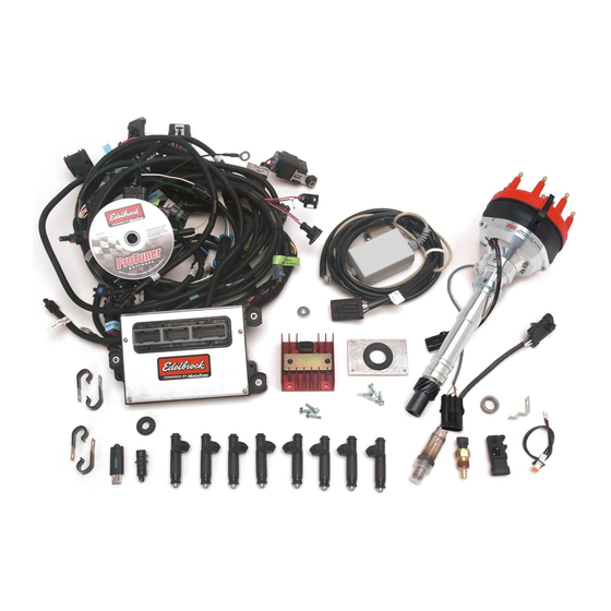
38-1515 Bulkhead Plates 68-0410 Self-Tapping Screws 72-1516 Grommet 1 3/4" O.D. 24-0301 Ignition Amplifier Kit 68-0410 Self-Tapping Screws 37-3517 Victor Pro-Tuner Kit 37-0004 RS485 Comms Cable 37-0006 USB Software Key (Basic Key) 37-0007 Controller ECM (48 Pin) 72-1517 ECM Rubber Grommet... - Page 8 37-3548 Malfunction Indicator Light w/ Clip 37-7119 1 Bar Map Sensor (Remove Orange Rubber) 38-3601 Gen III Map Sensor Bracket 37-3528 60 lb/hr High Impedance Injectors 67-1570 Injector O-ring Lube 37-3529 MSD Distributor w/ Cam Sync MSD PN 23451 37-3543 Temperature Sensor 37-3542 Oxygen Sensor Switching 52-9710 Oxygen Sensor Bung...
- Page 9 38-1515 Bulkhead Plates 68-0410 Self-Tapping Screws 72-1516 Grommet 1 3/4" O.D. 24-0301 Ignition Amplifier Kit 68-0410 Self-Tapping Screws 37-3523 Victor Pro-Tuner Kit 37-0004 RS485 Comms Cable 37-3524 USB Software Key (Pro Key) 37-0005 Controller PCM (80 Pin) 72-1517 PCM Rubber Grommet...
-
Page 10: Part Iii Installation And Setup
ECU, and begin the setup process to get your vehicle on the road! BEFORE BEGINNING! A clean and trouble free installation of the Pro-Tuner System is greatly enhanced by taking the time to organize and plan your installation before beginning. Perform the following: ·... - Page 11 The user assumes all responsibility for the application and use of the information and Edelbrock system software & hardware. While this guide should prove helpful; it is significantly condensed and simplified to allow...
-
Page 12: Strategies And Methods
(ECM) converts the analog inputs to digital signals and processes them within the 32 bit microprocessor. Outputs are conditioned as required for the assigned purpose. Your Edelbrock system is capable of three different fuel/timing control strategies. Modeled speed density uses sensor inputs along with a volumetric efficiency (VE) table... - Page 13 to estimate the airflow through the engine. The air fuel target table is used in conjunction with this calculated airflow to control the injector pulsewidth. The MAP-N strategy uses a base fuel map that varies as a function of engine speed and manifold pressure.
- Page 14 many conditions in which they should not be exposed – such as detonation or excessive temperatures. It is your job as a calibrator to balance all of the factors for your specific combination and program the best target values into the ECM that you can while keeping the engine in a safe operating window.
-
Page 15: Vehicle Installation
If you do not understand a procedure, contact the Edelbrock hotline. If you do not have the necessary skill or tools to perform any of the operations, consult a professional dealer/installer for assistance. - Page 16 Check automatic transmission shift points before removal of the stock system, and • adjust linkage after Edelbrock manifold installation for same shift points if needed. Determining Hood Clearance 1. CHECK HOOD CLEARANCE BEFORE REMOVING STOCK MANIFOLD. Use modeling clay or putty to make five small cones 2-3” high.
- Page 17 AFTER MEASUREMENT: COMPARING HEIGHT OF STOCK INTAKE ASSEMBLY AND VICTOR PRO TUNER ASSEMBLY. 1. Remove air cleaner from stock assembly. 2. Lay a straightedge across top of carburetor flange front to rear. 3. Measure from bottom of straightedge to manifold/block sealing surface of manifold at front and rear of engine.
- Page 18 EMISSION CONTROLS: The Edelbrock Victor and Super Victor Engine Management Systems will not accept stock emission control systems. Check local laws for requirements before installing this system. Not legal on pollution controlled applications.
- Page 19 HEADERS: For best performance, headers are recommended. Consult Edelbrock or your exhaust supplier for recommendations on header, pipe, and muffler specifications for your combination. INSTALLING THE EFI INTAKE MANIFOLD: The procedure for installing your new EFI manifold is nearly identical to installing a carbureted manifold.
- Page 20 Embossed side faces up. NOTE: In some cases, there may be a different right and left side gasket. Make sure both are placed correctly. 2. Coat head surface and both sides of gaskets with Edelbrock Gasgacinch #9300. 3. Apply Loctite 598 OEM High Temperature Silicone Gasket around water passages on head surface.
- Page 21 5. Re-connect throttle linkage and springs, transmission, cruise control, and fuel lines. Check all linkage for smooth throttle operation from idle to Wide Open Throttle (WOT). Note: Do not install with a throttle rod, use a cable actuated throttle. Throttle rods can transfer engine movement to the throttle and possible lead to binding.
-
Page 22: Fuel System Installation
Fuel System FUEL SYSTEM BASICS Because your Edelbrock Pro Tuner system controls fuel delivery very differently than a carburetor, some conversions to your fuel system may be necessary. Victor/Super Victor Pro-Tuner electronic fuel injection requires high and constant fuel volume and fuel pressure. - Page 23 Figure 2 FUEL PUMP AND FILTER The Victor/Super Victor Pro-Tuner system uses a single Edelbrock high-pressure electric fuel pump which is capable of pumping 50 or more psi (depending upon the pump). The pump relay will prime the system on key-up and shut down the pump if it does not receive an engine-run signal from the ECU, as in the case of a stall.
- Page 24 FUEL PRESSURE REGULATOR Fuel pressure is as important as fuel volume, particularly in fuel injection. The Victor/ Super Victor Pro-Tuner system requires that the fuel pressure regulator maintains a constant pressure at the injectors. It is recommended that Manifold Absolute Pressure references the regulator diaphragm to maintain constant pressure across all 8 injectors, regardless of fluctuating manifold pressure (vacuum) level.
- Page 25 2. Use the vehicle’s existing primary line as the fuel return line with modification to the pick up as described below. 3. Use the vehicle’s existing return line (if so equipped) as the fuel return line. This option applies only to vehicles previously equipped with fuel injection. If the vehicle is not already equipped with a return line, some fuel tank modifications are required for routing the return line through the sending unit plate back into the tank.
- Page 26 nut. Connect a length (at least 4 inches) of flexible return line (rubber or braided hose) to the fitting end. Connect the return line to the fuel pickup line using tie wraps. NOTE: THIS METHOD REQUIRES NO WELDING OF THE FUEL SYSTEM. NOTE: Whichever method you use to install the return fuel line, be careful to keep the end of the line away from the fuel pickup, as shown.
- Page 27 Installation and Setup Figure 6 Solder or weld the return hard line to the fuel pickup line.
- Page 28 Figure 7 - Completed return line installation FUEL SYSTEM INSTALLATION 1. Disconnect the vehicle battery. 2. Drain the fuel tank. 3. Remove all lines from the tank and carburetor. 4. Remove the fuel tank if sender plate is inaccessible. While fuel tank is removed from vehicle, it is recommended that it be professionally cleaned in order to remove any rust or dirt that may have accumulated inside which could damage the injectors.
- Page 29 3. Install the top of each injector into the fuel rail; carefully inserting the injector to avoid pinching or damaging the sealing O-ring. Orient the injector so that the connector is facing outward. (The outside of the rail has the Edelbrock logo on the side).
-
Page 30: Ecu And Main Harness Installation
Injectors should not bind in the ports. You should be able to rotate them slightly. A typical rail installation is illustrated in Figure 9. 3.2.2 ECU and Main Harness Installation ECU and Main Harness Figure 9 Visit us at: http://www.edelbrock.com... - Page 31 2. Mount the ECM and relays using only the grommets, bushing's, and washers provided. Use the Edelbrock ECU mounting bracket shown below for proper mounting and flexible orientation. These parts are specially engineered to insure proper isolation of the ECM.
- Page 32 3. Insure that the ECM case does not touch or rub against anything, particularly metal or wiring. The case voltage sources. 4. Do not mount hardware in such a manner as to cause stress on the harness. Do not pull, stretch, or kink wires and connectors. Minimize effect of engine torque movement on short sections of harness.
- Page 33 Installation and Setup Figure 11 - 80 pin Super Victor PCM The ECM (48 pin) or PCM (80 pin) controllers mount using specially designed bushing's and isolation grommets. When installing the mounts, first install the rubber grommets into the 3 mounting holes. Insert the bushing from the BACKSIDE of the grommet.
- Page 34 To mount the ECM or PCM inside the vehicle, a hole will have to be made in the firewall for the harness and connectors to pass through. A firewall bulkhead grommet and cover plate is included to seal the hole and support the harness where it passes through the firewall, or you can make your own.
- Page 35 Installation and Setup Figure 13 Before proceeding further with harness installation, install and mount all sensors and components.
-
Page 36: Component And Sensor Installation
Component and Sensor Installation COMPONENT AND SENSOR OVERVIEW: The diagram below identifies the location of the major components of the Pro-Tuner electronics. Not shown below is the air temperature sensor as it is normally mounted in the air cleaner base. -
Page 37: Distributor And Ignition
Visit us at: http://www.edelbrock.com Distributor and Ignition The Pro-Tuner Distributor with Cam-Sync is designed for use with our Victor Pro-Tuner EFI systems for the Small Block and the Big Block Chevrolet. The distributor includes an adjustable hold down collar (to accommodate various deck heights and custom intake manifolds), a large distributor cap, and the mechanical advance is locked out. - Page 38 DISTRIBUTOR KIT CONTENTS · 1 Pro-Tuner Distributor · 1 Rotor (MSD #8421) Installed · 1 Distributor Cap (MSD #8408) Installed · 1 Wire Retainer · 2 1.5” Long, Self Tapping Screws · 1 Distributor Gasket · 2 O-Rings · 1 Tube of Assembly Lube IMPORTANT INSTALLATION NOTES ·...
- Page 39 INSTALLATION PROCEDURE O-RING SEALS The Pro-Tuner Distributor features an o-ring groove in the uppermost bottom land of the housing in order to seal the oil gallery. The o-ring should only be installed if the block has been modified. See Distributor Specifications for procedure.
- Page 40 Make sure to install the spark plug wires one at a time and verify they are in the correct position. A wire retainer is supplied to secure the wires to the cap. Align the retainer with the mounting bosses, and use the supplied 1.5” self-tapping screws to secure the retainer.
-
Page 41: Intake Air Temperature Sensor (Iat)
Installation and Setup 3.2.3.2 Intake Air Temperature Sensor (IAT) Visit us at: http://www.edelbrock.com Intake Air Temperature Sensor Installing / Replacing the Intake Air Temperature (IAT) sensor The Intake Air Temperature sensor is a thermistor device which measures air temperature. This sensor must be installed into the air cleaner base. Drill the air cleaner base with a 3/4”... -
Page 42: Engine Coolant Temperature Sensor (Ect)
3.2.3.3 Engine Coolant Temperature Sensor (ECT) Visit us at: http://www.edelbrock.com Engine Coolant Temperature Sensor (ECT) Installing / Replacing the Engine Coolant Temperature (ECT) sensor The engine coolant temperature sensor is a thermistor device which measures coolant temperature. It should be screwed into the coolant passage of the intake manifold near the thermostat housing to measure coolant before it exits the engine on its way to the radiator. -
Page 43: Manifold Absolute Pressure Sensor (Map)
Installation and Setup 3.2.3.4 Manifold Absolute Pressure Sensor (MAP) Visit us at: http://www.edelbrock.com Manifold Absolute Pressure (MAP) Installing / Replacing the Manifold Absolute Pressure (MAP) sensor The MAP sensor measures pressure in the intake manifold. (A pressure below atmospheric is typical in a running engine, and is sometimes called vacuum when the value is referenced to atmospheric baseline.) The manifold pressure is low (high-... - Page 44 small length of vacuum line (not supplied) should be installed between the MAP sensor and the vacuum port reference location. Replacement of sensor should be done using the original mounting hardware. Note: If the MAP sensor has an orange ribbed sleeve on the reference port, remove it prior to installation.
-
Page 45: Idle Air Control Valve (Iac)
Installation and Setup 3.2.3.5 Idle Air Control Valve (IAC) Visit us at: http://www.edelbrock.com Idle Air Control Valve Installing / Replacing the Idle Air Control valve (IAC) The Idle Air Control (IAC) valve is controlled by the ECM and tailors airflow to help maintain a set point speed at idle. -
Page 46: Fuel Pressure Sensor (Optional)
3.2.3.6 Fuel Pressure Sensor (optional) Visit us at: http://www.edelbrock.com Fuel Pressure Sensor Figure 16 Installing / Replacing the optional Fuel Pressure Sensor An optional fuel pressure sensor may be used with your system to provide additional information to the ECU and for readout on digital smart gauges and displays over the CAN network. -
Page 47: Oil Pressure Sensor (Optional)
Installation and Setup 3.2.3.7 Oil Pressure Sensor (optional) Visit us at: http://www.edelbrock.com Oil Pressure Sensor Figure 17 Installing / Replacing the optional Oil Pressure Sensor An optional Oil pressure sensor may be used with your system to provide additional information to the ECU and for readout on digital smart gauges and displays over the CAN network. -
Page 48: Mass Air Flow (Maf) Sensor (Optional)
This will prevent Mass Airflow sensor faults during later operation. In high horsepower applications, your system is capable of running two of these sensors in parallel to keep restriction to a minimum. Consult your Edelbrock representative for information regarding adding and using a second sensor. - Page 49 Installation and Setup with a recommended sensor inlet tube installed.
-
Page 50: Throttle Position Sensor (Tps)
3.2.3.9 Throttle Position Sensor (TPS) Visit us at: http://www.edelbrock.com Throttle Position Sensor (TPS) The Throttle Position Sensor (TPS) comes installed on your throttle body and should require no mechanical adjustment. Scaling of the sensor is accomplished through the Setup Wizard. -
Page 51: Main Wiring Harness And Engine Wiring
Installation and Setup 3.2.3.10 Main Wiring Harness and Engine Wiring Visit us at: http://www.edelbrock.com Main Wiring Harness and Engine Wiring Figure 19 Once all sensors have been placed, the harness can be routed and connected to each. Lay the harness out and become familiar with each connection. Do not rush the harness installation. - Page 52 “dropout” between the Run and Crank positions. These types of ignition switches ARE NOT COMPATIBLE with your Edelbrock Pro-Tuner system. If you have such a switch; it must be replaced with a newer non-interruptible version for proper operation.
- Page 53 Fuel pressure should be rechecked at idle after engine has been configured. Do not crank the engine until the system has been configured using the Setup Wizard in your Pro-Tuner software. Installation and Setup If you have questions regarding wiring and connections;...
-
Page 54: Oxygen Sensors
ECU, which compensates when the air/fuel mixture is either rich or lean. If the exhaust system is already configured for an oxygen sensor port, simply replace existing sensor with the Edelbrock 4 wire sensor. Route and secure wire and connector away from exhaust heat. Allow enough slack for exhaust pipe movement. - Page 55 **IMPORTANT** If you decide to use a single or dual MotoTron or Edelbrock wideband oxygen sensor (UEGO) with external 0-5V conditioning - instead of the standard heated switching style (HEGO) with your 80 pin PCM, you must move 2 wires to different pins in the PCM connector.
- Page 56 Figure 22 1) Locate the “A” connector on the PCM harness plugs. It is the largest of the 3 connectors and contains 32 pins. The pins are numbered on the bottom side. Remove from PCM. 2) The cover of the connector must now be removed. Cut the tie-strap holding the harness bundle to the cover.
- Page 57 5) Before the signal wire/s can be relocated, they must be unlocked from the connector. On one end of the connector there is a white tab and on the other end is 2 white tabs. With a small screwdriver – push in on the single white tab as shown. You will feel it unlock as the dual white tabs on the other end protrude out.
- Page 58 Figure 25 Plug the connector/s back into the PCM. Reinstall the connector cover and re-strap the harness bundle to the cover. To return to the switching style sensor, reverse the procedure to put the wires in their original location. Check the wiring schematics for guidance if needed.
-
Page 59: Malfunction Indicator Light
Installation and Setup 3.2.3.12 Malfunction Indicator Light Visit us at: http://www.edelbrock.com Malfunction Indicator Light Installation To mount the Malfunction Indicator Light (MIL), drill a 5/16" hole in a suitable panel. Insert the MIL into the hole with the orange light facing toward you. Locate the MIL circuit in the engine harness. -
Page 60: Installing And Configuring The Software
Installing and Configuring the Software Visit us at: http://www.edelbrock.com Installing and Configuring the Software... - Page 61 Installation and Setup Installation and configuration of the software is much like any other Windows based application. It uses Install Shield and will prompt you for choices during the installation. In most cases choosing the "NEXT" button will give you the recommended default values.
-
Page 62: System Requirements
IT IS HIGHLY RECOMMENDED THAT YOU OBTAIN/USE A LAPTOP WITH THE NEWEST POSSIBLE MICROSOFT OPERATING SYSTEM AND THE FASTEST PROCESSOR SPEED WITH AS MUCH RAM AS POSSIBLE. THE PERFORMANCE OF YOUR PRO-TUNER SOFTWARE WILL BE MUCH IMPROVED WITH A HIGH PERFORMANCE PC; IN ADDITION, MICROSOFT DISCONTINUES SUPPORT OF THE OLDER OPERATING SYSTEMS - WHICH MAY CAUSE SOFTWARE RELATED PROBLEMS WITH THE PRO-TUNER INTERFACE. - Page 63 Installation and Setup OPERATING SYSTEMS ALSO HAVE IMPROVED HANDLING OF PERIPHERALS, USB PORTS, AND BETTER STABILITY THAN WIN98SE SYSTEMS.
-
Page 64: Installing The Software
2. Double click on the CD ROM drive icon 3. Double click on the EDELEFI_2_3_4_X.msi file on the CD ROM (the numbers may be different, depending on version and build ) 3. You will see installer start and prepare your computer for installation: Visit us at: http://www.edelbrock.com... - Page 65 Installation and Setup 4. Once the computer is ready, the installation will start: 5. Click NEXT >...
- Page 66 WILL EXPLAIN YOUR RIGHTS AND LIABILITIES IN THE USE OF THIS PRODUCT! 7. Click NEXT > once you have read and understand the license agreement 8. Choose the folder in which you want the Edelbrock Victor Pro Tuner software installed. IT IS HIGHLY RECOMMENDED YOU ACCEPT THE DEFAULT LOCATION PRESENTED IN THE INSTALLER.
- Page 67 Installation and Setup 9. The installer will now ask one more time to confirm the installation process. This will allow you to cancel the installation if you wish:...
- Page 68 To proceed, click "Install" The installer will proceed to install the necessary files on your computer ... the status will be displayed during the install: Once the install is completed, click the FINISH button and you are ready to use your new software!
- Page 69 Installation and Setup...
-
Page 70: Installing The Communications Hardware
3. USB Key (or "dongle") The key will be either a "Base" system key or a "Pro" level key. The key is required for the software to connect to the ECU. Connection: Before hooking up the laptop, be sure the following conditions are met: Visit us at: http://www.edelbrock.com... - Page 71 1. The laptop is booted and ready 2. The USB Key is plugged into an available USB slot on the computer 3. The Computer Connection cable is plugged into the Interface connector on the harness 4. The Computer Connection cable is plugged into the PC's serial port 5.
-
Page 72: Usb/Serial Converters
3.3.3.1 USB/Serial Converters Visit us at: http://www.edelbrock.com USB to Serial Converters Some laptops may not have a serial port (pictured below) Serial Port However, you can use one of the PC's USB ports and a USB/Serial Adapter (not included) that is readily available from many sources, including local consumer electronics stores. - Page 73 Edelbrock Pro Tuner software installation for the first time, the connection wizard will automatically detect and configure to use the appropriate device. If you already have the Pro Tuner software installed, you can manually add the new device to the list of communication ports for Pro Tuner by performing the following: 1.
- Page 74 2. Now choose "DEVICE MANAGER" to get a list of the installed and active devices for your PC. 3. Click on the "PORTS" Icon to expand the list of communications ports. You should see your USB to Serial Adapter in the list of ports. Often times, it will be assigned to COM4 if you don't have a lot of other devices attached to your PC.
- Page 75 4. Make a note of the COM port assignment and close the Computer Management window. 5. Now, RIGHT click on the MotoServer icon (the satellite dish) in the System Tray (lower right hand corner of your screen) 6. A menu will appear for MotoServer. Choose "Ports..." 7.
- Page 76 8. When you click "Edit Names", you will be presented a choice of pre configured ports. If the COM port you need is in the list, simply select that port and then click "OK". If it does not exist, click "Add" to add your new port. 9.
- Page 77 The new port name then appears in the Port Name listing. Make sure the new port is selected and then choose "OK" (or "Apply" if you have more ports to add). You will now be back at the Port Configuration window. Choose "Add " and then select the Type and Location with the drop down lists.
- Page 78 Be sure the Access Level is set to "4". Click "OK" and you will see the new Port Added to the Ports List. From now on, the Pro Tuner system will check to see if communications cable is plugged into any of the devices listed in the Ports Configuration List every time you start the program.
- Page 79 Installation and Setup Click "OK" to complete the set up.
-
Page 80: Connecting To The Vehicle
Vehicle ECU. Steps: 1. Start the Edelbrock EFI Application by double clicking on the Icon on your desktop: Edelbrock EFI 2. The application will start up and when it loads completely you will have a dialog that looks like: Visit us at: http://www.edelbrock.com... - Page 81 Be sure the ignition key is in the ON position and your USB key is installed in an available USB port on your laptop. To connect directly to the ECU, click on "Connect directly to your Vehicle's ECU" and then click on "OK ". To go into OFFLINE mode click "Open an existing calibration"...
- Page 82 Click NEXT Click NEXT...
- Page 83 Installation and Setup The computer has now found the proper port. Click NEXT. The computer is now ready to attempt to "talk" to the ECU. Click NEXT.
- Page 84 Once a connection is established successfully, click NEXT. Click NEXT to get the final results dialog.
- Page 85 Installation and Setup Click FINISH. 4. The software will now connect to the ECU and bring up the DASHBOARD screen:...
-
Page 87: Application Settings And Preferences
Installation and Setup 3.3.5 Application Settings and Preferences Visit us at: http://www.edelbrock.com Application Settings and Preferences Use this control panel to customize the application settings to your preferences. This control panel allows you to choose preferred units and default paths for files on your computer. - Page 88 Navigate to the desired storage location for calibration files and click "Apply" or "OK". You will then be advised with the following: Close all application windows and then restart the application. This will apply your new choices to the gauges, tables, MAP's and controls.
-
Page 89: Part Iv Basic Tuning With The Pro Tuner System
Installation and Setup Basic Tuning with the Pro Tuner System Visit us at: http://www.edelbrock.com Basic Tuning with the Pro Tuner System The Pro Tuner System is extremely powerful; however, a significant effort has been made to simplify the way information is presented to you to allow you to concentrate on the reason you bought the system - mainly reliability, horsepower, and drivability. -
Page 90: Setup Wizard
(a BOOKMARK). At that point, you can go directly to the area that you need to make changes to without stepping through the rest of the wizard. 4. Assuming this is the first time through, you will first see this screen: Visit us at: http://www.edelbrock.com... - Page 91 5. Click NEXT and watch the status bar at the bottom of the screen as it establishes a new connection to the ECU and configures it for programming. 6. The next screen will show you the Engine Setup wizard to help you configure your basic engine parameters: 7.
- Page 92 The wizard will then program the ECU. Please wait for it to finish completely: When programming is completed, you will be presented with the next wizard section to configure/choose your sensors. The WELCOME section will show a CHECK MARK to show that it has been completed:...
- Page 93 "Load Calibration from Disk". Navigate to the installed calibrations folder located at /Program Files/Edelbrock/EFI/ECUFiles/Cals. The MAP-N calibration file for the P/N 3670 Kit is identified as EDEL07E1EB_V004XDC_MAPN.hcal. The MAP-N calibration for the P/N 3690 Kit is identified as EDEL07P1EB_V004XDC_MAPN.hcal.
-
Page 94: Scaling Setup - Custom Load And Rpm Axis
If desired, the setup wizard can be used to define custom load and RPM axis. These 2-D tables define the breakpoints of any Pro-Tuner tables that vary as a function of engine load or speed. The breakpoints do not have to be linear or evenly spaced. You can define more closely spaced breakpoints at lower engines speeds and wider spaced ones at higher speeds where the engine will likely spend less time. - Page 95 Basic Tuning with the Pro Tuner System Custom tables for load ordinate: Custom tables for RPM ordinate:...
-
Page 96: Screens, Indicators And Tools
Examples of high resolution breakpoints are the base fuel and spark maps. Screens, Indicators and Tools Visit us at: http://www.edelbrock.com Screens, Indicators and Tools In this section, the various graphical screens, indicators and tools will be discussed in detail. - Page 97 Basic Tuning with the Pro Tuner System By clicking on the TABS along the top of the screen, you can see several other functions available for quick reference. At the bottom of the main screen, you will see a Status Bar. Watch this area for alerts, current activity, Faults, and user information.
- Page 98 Several specialized tools are available as Menu Options and can be activated by selecting them from the drop down menu bar at the top of the window.
-
Page 99: Dashboard
Basic Tuning with the Pro Tuner System 4.2.1 Dashboard Visit us at: http://www.edelbrock.com Dashboard TAB The DASHBOARD Tab is considered the "HOME" screen. From here you can monitor most critical engine functions quickly at a glance. The function of most of the gauges are self-explanatory, however there are a couple of... - Page 100 important point to note: Certain gauges will not appear in all configurations. For example, the optional oil • and fuel pressure gauges may or may not be on the screen, depending on your configuration (set in the Setup Wizard). The scaling of gauges (including the Tach) will adjust based on your Setup •...
-
Page 101: Maps
Basic Tuning with the Pro Tuner System 4.2.2 MAPs Visit us at: http://www.edelbrock.com MAP's Tab The MAP's tab gives you an abbreviated dashboard to use while you edit one of the available maps by either picking it from the drop down or by clicking on one of the buttons. - Page 102 You may edit one or more maps at a time. You can make changes by editing either the table or the 3D chart. Right clicking on the desired cell or group of cells will bring up choices for the actions you can take. The list is also available under the Edit menu in the header bar.
- Page 103 Basic Tuning with the Pro Tuner System manipulation .
-
Page 104: Details
4.2.3 Details Visit us at: http://www.edelbrock.com Details TAB The DETAILS tab gives you a more "in depth" numerical view of the various engine parameters and allows you to monitor several parameters (such as pulse width) that aren't available via other screens. Current conditions are displayed for Individual cylinder timing, injector duty cycle, and pulse widths. -
Page 105: Status Bar
CLICK on the Fault indicator to bring up the fault display. Connection Indicator - blinks green to indicate data is being received from the • Engine State - Stall, Crank, Run • Basic Tuning with the Pro Tuner System Visit us at: http://www.edelbrock.com... -
Page 106: About
4.2.5 About Visit us at: http://www.edelbrock.com About Screen This screen is accessed from the HELP menu bar option. It will give you basic information about the application (such as version number, Super Victor or Victor, etc.) This can be very helpful when contacting customer support or comparing with other... -
Page 107: System Information
Basic Tuning with the Pro Tuner System 4.2.6 System Information Visit us at: http://www.edelbrock.com System Information The "System Information" is available from the main menu HELP. This is the same as the "System Info" button on the ABOUT screen and is used to tell you about your PC configuration. -
Page 108: Tuning Maps
Tuning Maps Visit us at: http://www.edelbrock.com Tuning Maps... - Page 109 Basic Tuning with the Pro Tuner System Maps are basically tables that control a variety of fuel, air, timing, and behaviors necessary to define the limits and targets for various aspects of the engine operation. MAP TYPES...
- Page 110 In the Pro Tuner system, these Maps basically consist of two types: Simple tables - (such as coolant temp vs. idle RPM target) These tables often • actually a set of sliders such as the coolant temp vs. Idle RPM sliders in the Startup/Warm up Settings screen.
- Page 111 Simple tables are fairly intuitive in the way that you navigate and change values. The 3D tables/charts are also fairly intuitive, but they have some unique features that are worth noting, as shown in the following section: 3D CHARTS Specific Table of Contents items in HELP section "3D Chart Manipulation" •...
- Page 112 remind you of some of the powerful editing features available in the Maps. To disable this feature, click "Show Tips" check box. You can select a single cell in the table for editing by clicking on it. To modify the •...
- Page 113 Alternatively, you can use the EDIT menu in the menu bar to use the extended options. You can directly edit the 3D chart by selecting one or more intersections and using • the V,B,N,M keys. The corresponding cell in the table will also be updated. Basic Tuning with the Pro Tuner System...
- Page 114 At any time you can close the 3D chart viewer. To reopen it, go to the VIEW menu • on the table and choose " 3D chart" You can also turn on and off the ROW HIGHLIGHTING in the VIEW menu. •...
- Page 115 In the status bar at the bottom of the table, you will see the right hand panes show the current speed/load condition . When the ECU is "Learning/Auto Adapting", the parameters in the table may • change without user intervention (most evident on the Volumetric Efficiency map). This adaptation is based on the O2 sensor feedback and the Intake Air Adaptation strategy and can happen over a period of time as the ECU adapts the Map to current conditions.
-
Page 116: Base Fuel Map
4.3.1 Base Fuel Map Visit us at: http://www.edelbrock.com Base Fuel Map The Base Fuel Map is used to define fuel injector pulsewidth as a function of either manifold absolute pressure (MAP) or Throttle Position (TPS). A MAP-N tuning strategy uses MAP as the load axis. An Alpha-N tuning strategy uses TPS as the load axis. - Page 117 Basic Tuning with the Pro Tuner System Although these areas vary somewhat with engine design, the following diagram will give you an idea of where the engine will be operating under certain conditions. Once cranking / starting performance is acceptable, the areas most tuners will address next are: 1.
-
Page 118: Volumetric Efficiency Map
4.3.2 Volumetric Efficiency Map Visit us at: http://www.edelbrock.com Volumetric Efficiency Map The Volumetric Efficiency map is a representation of your engine's airflow characteristics. It needs to be properly calibrated for the control strategies to accurately determine fueling under all speed and load conditions, and to provide accurate altitude compensation. - Page 119 Basic Tuning with the Pro Tuner System The map is ordinated against RPM and Pressure Ratio. Pressure ratio is defined as manifold pressure over baro. It can be thought of as an indicator of load. As the pressure...
- Page 120 ratio goes up, the load is also increasing, and manifold vacuum is decreasing. To manipulate the map image and map functions, see 3D chart manipulation . Tuning Tips: The tuner has 3 methods of tuning the VE map. Once it is dialed in, you do not need to change it unless you change the engine airflow significantly.
-
Page 121: Spark Advance Map
Basic Tuning with the Pro Tuner System 4.3.3 Spark Advance Map Visit us at: http://www.edelbrock.com Spark Advance Map The spark map is one of the three main base combustion maps. The others are the VE or Base Fuel map, and the Air/Fuel target map. These three maps need to be calibrated throughout the range before significant work is put into tuning transients, idle, starting, or warm up. - Page 123 Basic Tuning with the Pro Tuner System Tuning Tips: Spark advance is specific to the engine combination. However, trends can be applied across various engines. The goal in determining optimum spark advance is to use the minimum spark advance required to maintain best torque at each speed/load point. Note that you can draw a comparison between a typical mechanical advance curve (for a carbureted application) and a fully programmable 3-D table as shown above.
-
Page 124: Target Air/Fuel Ratio Map
4.3.4 Target Air/Fuel Ratio Map Visit us at: http://www.edelbrock.com Target Air/Fuel Ratio Map The Target AFR map is where you input your desired fueling based on speed and load. To learn about chart and map functions and features, see the 3D chart manipulation section. - Page 125 Basic Tuning with the Pro Tuner System Tuning Tips:...
- Page 126 A stoichiometric ratio is 14.7:1. If you have your preferences set to display in equivalence ratio, 1.0 is a stoichiometric ratio. Generally, high performance engines will run best at that ratio or less (richer). At idle and light load, the AFR can usually be at or near 14.0-14.8.
- Page 127 Basic Tuning with the Pro Tuner System 0.712 1.405 20.66...
-
Page 128: Accel/Decel Fuel Settings
4.3.5 Accel / Decel Fuel Settings Visit us at: http://www.edelbrock.com Accel/Decel Fuel Settings To access the Transient Fuel Map, select the Accel/Decel Fuel Settings from the drop down list in the Tools menu. - Page 129 Basic Tuning with the Pro Tuner System Tips for Tuning: It is important to remember that the Accel/Decel strategy will tune deceleration as well as acceleration and load dump fueling. Start modifications conservatively! ALWAYS complete and optimize ALL steady state mapping and idle calibration before tuning transient running! Otherwise your base fueling may be affected by transient settings.
- Page 130 controller will lookup a calibrated value in the table/s and multiply the fueling by that amount and decreasing until there is no meaningful difference between the Raw and Filtered values. So if the Raw sensor value has changed a great deal in a short period, the delta (or difference) will be large, which will require a greater amount of transient fueling in that cell of the table to maintain the desired AFR for that period than a small delta would.
- Page 131 Basic Tuning with the Pro Tuner System value other than that will act as a global transient multiplier. It is better to only use the main delta tables to tune the transient at operating temperature! A multiplier value in the transient maps or ECT Trans Fuel Mult Tbl is a function of percentage.
-
Page 132: Closed Loop Compensation (Clc) Map
4.3.6 Closed Loop Compensation (CLC) map Visit us at: http://www.edelbrock.com Closed Loop Compensation (CLC) Closed Loop Compensation (CLC) map - Fuel Adaption The Closed Loop Compensation (CLC) map is a map where the fuel pulse width is dynamically adjusted to provide the engine the desired air/fuel ratio by applying a multiplier to the fueling to correct for any error which may exist in the base fuel map or dynamic flow changes in the rails or injectors. - Page 133 Basic Tuning with the Pro Tuner System The map can be edited just like any of the other main maps. See 3D chart Manipulation. Tips for tuning: The CLC map is adapted at the rate dictated by the Fuel Adapt Gain table. It is desirable to adapt the map slowly over time so that the system will capture evolving changes in the engine's condition and not adapt instantaneous values that may not be accurate.
- Page 134 table is a function of speed and load, and is calibrated manually or adapted as a multiplier on base fueling. This means that a value of 1.00 equals the calibrated base fueling and no change is being applied to the end pulse width of the injector. A value of 1.10 equals 10% more fuel is being delivered than is mapped to make the actual AFR equal the desired mapped AFR.
-
Page 135: Ect Fuel Trim Table
Basic Tuning with the Pro Tuner System 4.3.7 ECT Fuel Trim Table Visit us at: http://www.edelbrock.com ECT Fuel Trim Table ECT Fuel Trim Table (Not Available in Speed Density Mode) In Speed/Throttle (Alpha-N) mode or Speed/Pressure (MAP-N) mode, there is the ability to adjust a global trim for fuel based upon ECT. -
Page 136: A/C Load Compensation
4.3.8 A/C Load Compensation Visit us at: http://www.edelbrock.com A/C Load Compensation A/C Load Compensation Insure that the ECU input wire for A/C clutch sensing is correctly configured before continuing. Note: When wiring A/C load compensation, Pin M (PCM80) / Pin A (ECM48) in expansion connector must be pulled to ground when A/C compressor is energized. - Page 137 Basic Tuning with the Pro Tuner System Generally, the most compensation is required at the lowest speeds & loads. In the tables this would mean the low percentages of throttle opening. The amount of load compensation required decreases with an increase in throttle opening. The tables work together to maintain engine speed when a sudden load is applied.
-
Page 138: Iat Fuel Trim Table
4.3.9 IAT Fuel Trim Table Visit us at: http://www.edelbrock.com IAT Fuel Trim Table IAT Fuel Trim Table (Not Available in Speed density Mode) In Speed/Throttle (Alpha-N) mode or Speed/Pressure (MAP-N) mode, there is the ability to adjust a global trim for fuel based upon IAT. This can be useful if fueling characteristics change greatly with engine coolant temperature. -
Page 139: 3D Chart Manipulation
Basic Tuning with the Pro Tuner System 3D Chart Manipulation Visit us at: http://www.edelbrock.com 3D Chart Manipulation In the following subsections, you will learn the various powerful ways you can interact with a 3D chart to get the view that you need to interpret the data. These methods are easy to use and involve using the correct combination mouse buttons and keyboard keys. -
Page 140: Edit Chart Point
Below is the list of functions available with almost every chart and table in the Pro-Tuner system. You can also bring up this menu under the Help section of the online interface, or by pressing Ctrl-H while in any table or chart. - Page 141 Basic Tuning with the Pro Tuner System B - Decrements the value(s) of a selected region by 0.01 CTRL-S - Starts MotoBall (this is the tracking highlight) CTRL-Q - Stops MotoBall CTRL-A - Select all. CTRL-I - Interpolate a selected region. (Interpolate smooths a column, row, or surface based on the value in each corner of the selected area) CTRL-F - Auto-fill a selected region with a value.
-
Page 142: Rotate
While rotating, the grid will take on the appearance below. Releasing the mouse button will redraw the chart in your chosen position. You can put the view back to the original position by selecting VIEW / Reset View or selecting Ctrl+R. Visit us at: http://www.edelbrock.com... - Page 143 Basic Tuning with the Pro Tuner System...
-
Page 144: Zoom Chart
Upon releasing the mouse buttons, the window will redraw at your zoom rate. At anytime you can choose RESET VIEW and the view will be rotated and resized to the default view. To RESET the view to the previous view, select View / Reset View ". Visit us at: http://www.edelbrock.com... -
Page 145: Move View
Basic Tuning with the Pro Tuner System 4.4.4 MOVE view Visit us at: http://www.edelbrock.com 3D Chart MOVE To MOVE the chart position within the window, hold down the SHIFT key and then click the LEFT MOUSE BUTTONS and drag it to the desired position within the chart window. -
Page 146: Reset View
At anytime you can choose RESET VIEW and the chart view will be rotated and • resized to the default view. To RESET the view to the previous view, type "Ctrl +R " or select view/reset view. Visit us at: http://www.edelbrock.com... -
Page 147: Logging And Data Viewing
Basic Tuning with the Pro Tuner System Logging and Data Viewing Visit us at: http://www.edelbrock.com Data Logging and Data Viewing The Logging tool is a very powerful and useful way to see what is going on in your system. This tool is available from the main Dashboard by choosing the "PC DATA LOGGING"... - Page 148 ADD PARAMETER(S) This window allows you to display, save, load and print data captured from the ECU. To get started, choose a parameter from the drop down list in the lower left corner. Then click on the " ADD " button to add it to the plot.
- Page 149 Click the green arrow to start a display/recording or to resume display of your chart data after you pause the display (using the || button). When PAUSED , the logger is not saving data to the file for later viewing. OPEN SAVED DATA LOG Use this button to open a file dialog and pick a previously saved data log for viewing.
- Page 150 or the other button. The entire chart area will then zoom in or out. ZOOM BOX To selectively zoom in on a particular area of the chart or dataset, use the ZOOM BOX. To use it, click on button and then click and drag to select the area of data you are interested in on the chart. The chart will zoom in on that area.
-
Page 151: Initial Start Up And Idle Tuning
1. With the key in the on position and the PC connected to the ECU, view the dashboard tab in Pro-Tuner and verify that the intake air temperature and engine coolant temperature indications make sense (indicate near ambient if the engine is cold). - Page 152 8. Highlight the entire CrankFuelMap table as shown. 9. Crank the engine. If it doesn't start after approximately 5 seconds, use the V, B, N or M keys to increase or decrease the values in the CrankFuelMap. Repeat until the engine starts and runs.
- Page 153 screen then click on the "Base Fuel Map" button. 11.In either the base fuel map table or graph view, go to "Options" and select 'Start Motoball". This will give you a graphical indication of where the ECU is accessing the table values.
- Page 154 15.While the engine is warming up, check for leaks. 16.An engine coolant temperature indication is included in all Pro-Tuner screen tabs. Monitor your engine temperature as the engine is warming up. If it begins to overheat, shut down and resolve the problem before continuing the tuning process.
-
Page 155: Tps Set Points
Keep adjusting and checking until the actual engine RPM is very near the target and the IAC DC% is varying between 20 and 30%. TPS Set Points Basic Tuning with the Pro Tuner System Visit us at: http://www.edelbrock.com... - Page 156 Throttle Position Sensor Set Points This tool is accessed via the TOOLS Menu and selecting TPS Set Points. This tool is used to ensure the Throttle Position Sensor (TPS) is correctly adjusted for the system "Baseline". It changes the voltage value of the sensor into a percentage for easy reference during calibration.
- Page 157 MAXIMUM SET POINT Be sure to remove any obstructions to Wide Open Throttle, such as floor mats, • binding linkage, transmission kick down cable too tight, etc. Floor the throttle (allowing the throttle blades to fully open). Visually check that •...
-
Page 158: Ignition Sync Offset
Ignition Sync Offset Visit us at: http://www.edelbrock.com Ignition Sync Offset Tool It is necessary before beginning any calibration efforts to set the ignition timing reference (Ignition Sync). The function of the Ignition synchronization is to match the actual Top Dead Center location of the #1 cylinder - to the software so that the system displays the timing events that the engine actually sees. - Page 159 Basic Tuning with the Pro Tuner System the spark advance value displayed. Check the actual spark advance with the timing light. Move the slider or type in the value higher or lower by moving the number of degrees of difference between the readings. For example, if the display shows 18 degrees and the timing light shows the engine at 22 degrees, move the offset 4 degrees to bring the actual timing into agreement with the display.
-
Page 160: Offline Mode
OFFLINE Mode Visit us at: http://www.edelbrock.com OFFLINE Mode OFFLINE mode is used to edit a "tune" or "HCAL" without the laptop connected to the vehicle. It allows you to LOAD an HCAL, edit various maps and parameters, save it to disk and then use it later when connected to the vehicle. - Page 161 Basic Tuning with the Pro Tuner System Once the desired file has been chosen, you will be presented with a Control Panel that allows you to Edit elements of an HCAL file. To edit the various parameters, click on the desired button. The "EDIT ... Map" buttons will allow you to edit the various tuning Maps just like you do when online.
- Page 162 Some of the options (such as Auto Refresh) are not available offline (for obvious reasons); so they may inform you that they are not available OFFLINE. The "EDIT ... Settings" buttons allow you to use the same interface as you use online to set various parameters.
- Page 163 Basic Tuning with the Pro Tuner System OFFLINE editing and behavior is discussed in more detail in the following sections.
-
Page 164: Offline Load
4.9.1 OFFLINE LOAD Visit us at: http://www.edelbrock.com OFFLINE LOAD While in the OFFLINE mode, you can load any save HCAL file by choosing the "LOAD" button. This will populate the MAP's and other editable parameters and allow you to manipulate them. You not only can make and save changes to a calibration offline, but you can open multiple cal's offline with the compare cal button. -
Page 165: Offline Save As
Basic Tuning with the Pro Tuner System 4.9.2 OFFLINE SAVE AS Visit us at: http://www.edelbrock.com OFFLINE SAVE AS To SAVE changes you have made to a calibration with a new file name, choose the " SAVE AS" button. This will prompt you to enter a filename and save it to the disk. -
Page 167: Offline Save
Basic Tuning with the Pro Tuner System 4.9.3 OFFLINE SAVE Visit us at: http://www.edelbrock.com OFFLINE SAVE To SAVE your calibration changes to the same file as you loaded or imported, choose SAVE. -
Page 168: Offline Save And Use Online
4.9.4 OFFLINE SAVE and USE ONLINE Visit us at: http://www.edelbrock.com OFFLINE SAVE AND USE ONLINE To SAVE your calibration changes and then use them with a connected ECU, choose the SAVE and USE ONLINE button. You will first be notified that the file has been saved reminded to check your connection. -
Page 169: View Logger Data
Basic Tuning with the Pro Tuner System 4.9.5 View Logger Data Visit us at: http://www.edelbrock.com Viewing Logger Data To view previously captured PC Logger Data or Flight Recorder Data, simply choose "Load Saved Logger Data" from the OFFLINE control panel. A viewer window will then... -
Page 171: Part V Advanced Tuning With The Pro Tuner System
Basic Tuning with the Pro Tuner System Advanced Tuning with the Pro Tuner System Visit us at: http://www.edelbrock.com Advanced Tuning with the Pro Tuner System This section deals with many of the more advanced tools and techniques to use with your... -
Page 172: Warm Up Fine Tuning
Warm Up Fine Tuning Visit us at: http://www.edelbrock.com Warm Up Fine Tuning Starting and Warm up calibration is done through the following screen: The Crank IAC slide controls will set the amount of crank airflow vs. engine coolant temperature. The Crank Spark Advance will set the amount of spark advance during cranking. It can be varied according to crank rpm. - Page 173 Advanced Tuning with the Pro Tuner System In the upper right hand side of the page is the crank fueling map. Crank fuel is mapped against rpm and coolant temperature. The units are in FPC (Fuel Per Cycle) in mg/cyl. when running Speed/Density mode.
-
Page 174: Idle Fine Tuning
Idle Fine Tuning Idle calibration is one of the most important tuning parameters in achieving good stability and optimum drive-ability. The Edelbrock idle tuning interface allows great flexibility while in an easy to use format. The idle screen contains 3 major areas: The idle speed control panel - (top array of slide controls) Lets you control the •... - Page 175 The idle control gains - (bottom array of slide controls) will tune the behavior of • the idle controller. During idle mode, your ECM will control the idle speed by automatically adjusting spark advance and idle airflow. These sliders let you tune the system for your combination.
- Page 176 Generally, you will want to use very little if any D gain, slightly more P gain, and fairly small I gains. Small adjustments make significant changes. Tune the gains at operating temperature. Use the minimal gains required to provide smooth idle and prevent surging or stalling.
-
Page 177: Toggle Closed Loop
Advanced Tuning with the Pro Tuner System Toggle Closed Loop Visit us at: http://www.edelbrock.com Toggle Closed Loop This This feature toggles on/off the Closed Loop Correction (CLC) feature. The driver's side sensor is always the primary sensor. Always plug into the driver side only when using a single sensor. -
Page 178: Ve Estimator Tool
Visit us at: http://www.edelbrock.com VE Estimator Tool In most cases, the Volumetric Efficiency map in the Pro-Tuner default calibration provides a good base for initial startup and tuning. Alternatively, the VE Estimator Tool can be used as a good way to quickly get a base Volumetric Efficiency Map in the calibration for initial tuning. - Page 179 Advanced Tuning with the Pro Tuner System Use the normal 3D Map manipulation methods to rotate and scale the 3D display or change the font size of the table. The map immediately applies changes to the VE map in the ecu calibration. You can revert to the previous map, or reload the original map. Unless you have an unusual combination - for which you would need to use the VE Estimator, the VE map that is in your ECU after initial programming is usually very good to get started with.
-
Page 180: Adaptive Fuel "Autotuning" Capabilities
Adaptive Fuel "AutoTuning" Capabilities Visit us at: http://www.edelbrock.com Adaptive Fuel "Auto Tuning" Capabilities In addition to (or instead of) adaptation of airflow (VE) with MAF sensor/s in Speed/ Density mode, the system can be setup to run single or dual approved switching OR wideband oxygen sensors in all control modes: Alpha-N (speed/throttle), MAP-N (Speed/ Pressure), or true Speed/Density modes. - Page 181 normal operation. Although the fuel injectors are characterized for the system, small variations occur because of fuel rail dynamics (causing pressure pulses in the system), pressure delta differences between cylinders, system wear, etc. Closed loop fuel adaptation is meant to adjust for these inconsistencies.
- Page 182 the setup wizard. This will deselect the sensor and set the system for open loop (no O2 feedback) operation. Open loop is generally recommended for dedicated drag racing.
-
Page 183: Oil Pressure Warning Set Points
Advanced Tuning with the Pro Tuner System Oil Pressure Warning Set Points Visit us at: http://www.edelbrock.com Oil Pressure Warning Set Points This tool is accessed via the TOOLS Menu and selecting Oil Pressure Warning Set Points. To change the warning set point for each RPM, simply type your desired pressure in the input box. -
Page 184: Coolant Fan Output
ECM output wire or ECM damage will occur! NOTE 2: To use the fan control feature, you must add the Edelbrock fan relay wire to your ECM. On 48 pin units, the wire must be inserted into pin A3 (pin 3 of the A connector). -
Page 185: Coolant Fan Set Points
Advanced Tuning with the Pro Tuner System Coolant Fan Set Points Visit us at: http://www.edelbrock.com Coolant Fan Temperature Turn On Threshold This tool is accessed via the TOOLS Menu and selecting Coolant Fan Settings. To change the Fan Turn On Temperature, simply move the slider or type your desired temperature in the input box. -
Page 186: Fault Detection And Troubleshooting
Fault Detection and Troubleshooting Visit us at: http://www.edelbrock.com Trouble Codes/Faults Trouble Codes or Fault Codes are indicated by the FAULT indicator at the bottom right hand corner of the screen status bar. This indicator will light up either YELLOW for warnings or RED for faults. - Page 187 This view will show you three categories of Fault Codes: Active Faults Active Faults are faults that are currently being reported by the ECU and the ECU is reacting to these faults according to the strategies in place. Occurred Faults The Occurred Faults category is basically a history of faults that have been detected and Active at one point or another.
- Page 188 condition to make them "Active" has yet to be confirmed. This category can be helpful to spot potential momentary or intermittent faults or incorrect calibration values. In any category of fault, if you click on the fault text, it will take you to the appropriate section of the HELP file to further explain the code and to suggest possible causes and diagnostic procedures, if available.
-
Page 189: Reset Ecu To Last Programmed Setup
Advanced Tuning with the Pro Tuner System 5.10 Reset ECU to last programmed setup Visit us at: http://www.edelbrock.com Reset to Last Programmed Setup This feature is accessed via the File Menu from the any of the main screens. It will reset all the MAP's, values, and wizard choices back to the preset values that the user started with after the wizard last programmed the ECU. -
Page 190: Part Vi Features Available With Pro Option Only
Features Available with Pro option only Visit us at: http://www.edelbrock.com Features Available with Pro option only In this section, you will learn about several advanced features available with the Pro Option option only. -
Page 191: Additional Maps
For individual cylinder control, the cam sensor equipped distributor which is included with your Pro-Tuner system can be used, or an encoded crankshaft trigger is required: (A distributor may be used in conjunction with an encoded crank trigger, with individual cylinder spark control available with a distributor.) With an... - Page 192 However, if it is used with an approved cam sensor it can provide individual cylinder control. Discuss the cam sensor options for use with the flying magnet trigger with your Edelbrock support expert. Individual Cylinder Fueling Control (Pro Option Only) The FuelMult1-4 Maps provide individual cylinder offset to optimize power and economy.
- Page 193 Features Available with Pro option only Tips for tuning: The fueling maps for each cylinder act as multipliers, offsetting the fuel from the base value. That is, a value of 1.0 is NO change from the base fueling. A multiplier greater or less than 1.0 will change the fueling for that cylinder by that percentage from the base value.
- Page 194 to the base spark map values for the cylinder being adjusted. This feature can help compensate for differences between cylinders due to fueling or airflow differences, or exhaust, combustion chamber, or temperature variation of a cylinder from the other cylinders. When used properly in combination with the individual fueling control; the engine can be tuned for optimum performance and reliability.
- Page 195 Features Available with Pro option only Tips for tuning: Unlike the individual fuel maps; the individual spark tables are NOT a multiplier table. The entered value represents a number of crankshaft degrees of timing difference from the main spark advance map for the load/speed point. So, if no change from base advance is desired - simply enter "0"...
- Page 196 Tips for tuning: It is recommended only VERY experienced tuners change the values in the Fuel Adapt Gain table. Gains too aggressive will cause instability or non-typical values to be adapted to the CLC map, particularly if an O2 sensor begins to fail. Small gains are strongly recommended.
- Page 197 Features Available with Pro option only Tips for tuning: The table is an offset to the main Spark Advance map. It is based on coolant temperature in degrees C. or degrees F. (Whichever you have chosen as your desired units of temperature in the application settings.) A value of "0"...
- Page 198 In Speed/Throttle (Alpha-N) mode or Speed/Density mode, there is the ability to adjust a global trim for spark advance based upon MAP. This can be useful if ignition characteristics change greatly with ambient air pressure. While not often needed, the MAP Spark Trim table can be helpful in providing a global spark retard for a very hot intake charge in order to help avoid detonation.
- Page 199 Tips for tuning: Note: This table should only be adjusted by experienced tuners! In general, this table should need no adjustment and the calibration will be loaded for you by the setup wizard based upon your O2 sensor selection. Although the table defines a band around stoich, as a performance tuner - you generally only have to think about the rich limit that you want to allow closed loop operation to occur, since performance engines very seldom are tuned leaner than stoichiometric anyway.
- Page 200 1.208 0.828 1.188 0.842 1.167 0.857 1.145 0.873 1.125 0.889 1.105 0.905 1.083 0.923 1.063 0.941 1.042 0.96 1.020 0.98 1.000 0.964 1.037 0.928 1.078 0.892 1.121 0.855 1.169 0.820 1.22 0.784 1.276 0.748 1.337 0.712 1.405 For more information regarding closed loop operation and adaptive functions, see the section on Adaptive Tuning Capabilities.
- Page 201 adapted operation where it is unnecessary to attempt to adapt further. When entering values in the other cells: TAKE GREAT CARE - DO NOT PUT TOO LARGE OF VALUE IN THIS TABLE! A large value can cause erratic adaptation and poor running because it can adapt a false value captured during a misfire, IAC modulation, or other nearly instant or non-typical running condition.
- Page 202 There are other maps and tables available which simply provide another way to access main maps or features listed in other tabs of your Pro-Tuner software; such as the transient maps, Base Fuel map, Main spark Advance map, etc. See the section on the...
-
Page 203: Flight Recorder
Features Available with Pro option only Flight Recorder Visit us at: http://www.edelbrock.com Onboard Flight Recorder (Pro Option Only) The Flight Recorder function is used to control the ECU data capture system that is resident on the ECU. This recorder is available for use without a PC, so is a valuable tool for logging during an event or a driving session. - Page 204 and trigger. First, check the STATUS indicators. If you see the GREEN "Data Available" light lit, it indicates that you have a previously recorded data. You can click on the "VIEW" button to view this data, or you can ignore it, set up new parameters and re ARM the trigger (which will erase the previously recorded data).
- Page 205 Features Available with Pro option only Once you have chosen your parameters and record trigger, use the slider bar for "Scan Rate" to select the frequency at which these parameters will be recorded. As you move the slider, notice that the record duration and remaining displays will adjust accordingly.
-
Page 206: Virtual Engine Simulator
Virtual Engine Simulator Visit us at: http://www.edelbrock.com Virtual Engine Simulator (Pro Option Only) The Virtual Engine Simulator functions is accessed by going to the "TOOLS" menu and selecting "Virtual Engine Simulator " menu option. - Page 207 Features Available with Pro option only This tool is very valuable when troubleshooting or verifying proper operation of the system in a "test" mode or before firing the engine. It can help identify a bad injector or ignition component. When you first open the simulator, you will be reminded to disconnect the fuel pump harness to prevent flooding of the engine: To use the simulator, click on the slider and select the RPM you wish to have the engine to simulate.
-
Page 208: Base Fuel Pressure Set Point
Pressure Correction: The Pro-Tuner system can automatically correct your fuel injector pulse width for changes in base fuel pressure. Fuel pressure correction will increase or decrease the injector open time if fuel pressure drops or increases for any reason. - Page 209 Features Available with Pro option only require a table be manually calibrated for fuel pressure compensation - the Pro-Tuner system can perform this automatically for any base pressure that you set. In some cases, tuners decide to change overall fuel delivery by adjusting the pressure regulator.
-
Page 210: Adaptive Air "Autotuning" Capabilities
Adaptive Air "AutoTuning" Capabilities Visit us at: http://www.edelbrock.com Adaptive Air "AutoTuning" Capabilities (Pro Option Only) Mass Air Flow (MAF) Adaptation This tool allows you to monitor and control the Mass Airflow Adaptation capabilities of the Pro Tuner system. This functionality basically "learns" via an advanced ECU strategy how to keep the air/fuel mixture at your requested Target Air Fuel Ratio. - Page 211 Features Available with Pro option only You may run single or dual GM digital mass airflow sensors in Speed/Density, greatly increasing the adaptability of your system. You may choose to run MAF sensor/s as a permanent installation for continuous learning of the VE map and compensation for engine airflow mods or engine wear and degradation.
- Page 212 the indicator is below the green band, it indicates that the system is "taking out" airflow and the values in the map are too high. The LEARN / LEARN INACTIVE LED will light when the ECU is actively adapting. Typically, adaptation will take several minutes to "hone in" at different steady state loads and speeds before it is complete.
- Page 213 The "Learn Disabled" button allows for user override of the adaptation behavior. There may be cases where you have a calibration that is tuned for a very specific purpose and you don't want the ECU VE adaptation changing this. In that case you can turn the adaptation off by using the Learn Enable/Disable Button.
-
Page 214: Part Vii Appendices
Appendices Visit us at: http://www.edelbrock.com Appendices These sections provide more detailed and helpful information that will help you enjoy your new Pro Tuner System. -
Page 215: Engine Controller Pinout Sheets
DRVG-B Connector B XDRG CAT-AN9 MAP-AN1 LEVEL-AN14 VR-CNK+ VR-CNK- XDR-AN18 O2 PASS-AN5 DG MAF-DG4 Visit us at: http://www.edelbrock.com Channel Name Injector Injectors 4/7 Injector Injectors 5/8 Switched ground CAN1+ Customer Interface pin J Comms- Diagnostic pin C Knock sensor #1... - Page 216 CAM DG O2 DRV AN2 XDR-AN3 THERM-AN11 CLNT-AN10 EST 3 EST 4 EST RTN B18 ECUP 51K PU-AN15 TPS-AN4 XDRP THERM-AN19 EST 1 EST 2 PCM Pinout Mototron Name Connector A ECUP O2A+ (AN16) A10 AN8 A11 CAN1+ A12 O2A- (AN17) A13 O2B+ (AN19) A14 AN9 A15 AN10...
- Page 217 A29 EK0P A30 EK1P A31 CAN2+ A32 CAN2- Connector B EST RTN EST1 MPRD CNK- CAM DG OILP START EST5 B10 EST3 B11 FUEL P B12 TACH B13 CNK+ B14 CNK DG B15 DG1 B16 DG2 B17 DRVP B18 DRVP B19 AI4 B20 FI4 B21 AI3...
-
Page 218: Frequently Asked Questions (Faqs)
How do I check the fuel pressure and what should the pressure be? You should install a Schrader valve on the front of the passenger side fuel rail for testing or install the optional fuel pressure sensor for the Pro-Tuner system. To test for system leaks, (internal or external): Connect a fuel pressure gauge to the Schrader valve. -
Page 219: Trouble Codes/Faults
Appendices Trouble Codes/Faults Visit us at: http://www.edelbrock.com Trouble Codes/Faults Trouble Codes or Fault Codes are indicated by the FAULT indicator at the bottom right hand corner of the screen status bar. This indicator will light up either YELLOW for warnings or RED for faults. - Page 220 This view will show you three categories of Fault Codes: Active Faults Active Faults are faults that are currently being reported by the ECU and the ECU is reacting to these faults according to the strategies in place. Occurred Faults The Occurred Faults category is basically a history of faults that have been detected and Active at one point or another.
- Page 221 condition to make them "Active" has yet to be confirmed. This category can be helpful to spot potential momentary or intermittent faults or incorrect calibration values. In any category of fault, if you click on the fault text, it will take you to the appropriate section of the HELP file to further explain the code and to suggest possible causes and diagnostic procedures, if available.
-
Page 222: Maintenance Procedures
Maintenance Procedures Visit us at: http://www.edelbrock.com Maintenance Procedures In this section, you will find several helpful maintenance procedures, including sensor replacement procedures and periodic maintenance procedures for your Victor Series EFI kit. -
Page 223: Tps Replacement
3. Remove the screws on the TPS holding it to the throttle body (see Figure X2) 4. Remove the sensor 5. Insert the new TPS into the throttle body (see Figure X3) 6. Bring up the Edelbrock Victor Series EFI application and choose the Setup Wizard from the Tools menu Appendices... - Page 224 7. Choose the "TPS Set Up" tab in the Setup Wizard 8. Reconnect the wiring harness to the sensor. 9. Adjust the new TPS as necessary to achieve a minimum TPS setting of YY-ZZ counts. Once this is achieved, tighten the screws to secure the sensor. Turn the minimum air bleed screw the number of turns discovered in step one to reset the idle.
-
Page 225: Glossary
(compression stroke or overlap), since the camshaft is rotating at ½ crank speed in a 4 cycle automotive engine. This allows for individual cylinder control. Controller Area Network: An electronic communications method for connecting various controllers. Appendices Visit us at: http://www.edelbrock.com... - Page 226 (TDC). The value (in degrees) of the crankshaft revolution. When referred to in the Pro-Tuner Setup Wizard, it describes the individual crank pin offset from the #1 cylinder. With the Pro USB key, the user can program custom firing orders for flexibility in crankshaft designs, including "odd fire"...
- Page 227 Control Module) or ECS (Engine Control System). Various manufacturers have a variety of acronyms for the controller. The Pro-Tuner refers to the ECU specifically as "ECM" for the 48 pin ECU and "PCM" for the 80 pin ECU. Equivalence Ratio Actual air/fuel ratio divided by the air/fuel ratio at stoichiometry.
- Page 228 Gain (Integral) Gain (Proportional) Horsepower Ignition Sync Offset Injector Lambda Load This controls the acceleration based on change, or basically the how fast the rate of change is adapted or integrated. Example: Increasing the Integral Gain on an IAC will make it change faster and be more “sensitive”.
- Page 229 Sensors can be heated or unheated. The heated sensor in the Pro-Tuner system provides better control than unheated sensors. A wide band style O2 sensor has a linear curve representing a wide range of air fuel ratios, usually reading from 10:1 up to 18:1 for gasoline.
- Page 230 Pressure Ratio Rev Limit (Hard) Rev Limit (Med) Rev Limit (Soft) Semi-Sequential Injection Sequential Injection With a cam sensor or other method of determining and Sequential Spark Serial Spark Advance Speed Density Stoichiometric Supercharger (PR): Ratio of Engine manifold pressure to barometric (ambient) pressure.
- Page 231 Target AFR/EqR Current fueling target, based on the inputs to the ECU model. The ECU will be adjusting to this value as necessary to based on this target (from the Target AFR map). Tau X An advanced transient fuel strategy that calculates and maintains the Air Fuel Ratio during rapid changes in air movement or engine load.
-
Page 232: Additional Resources/Service
WARRANTY It is the constant endeavor of the Edelbrock Corp. to provide our customers with the highest quality performance products. Edelbrock warrants the Edelbrock Victor/Super Victor Pro Tuner Systems to be free from defects in both workmanship and materials for... - Page 233 Appendices...