Garmin GHP 20 Marine Autopilot System with SmartPump Installation Instructions Manual
Hide thumbs
Also See for GHP 20 Marine Autopilot System with SmartPump:
- Owner's manual (28 pages) ,
- Product information (37 pages) ,
- Installation instructions manual (20 pages)
Table of Contents
Advertisement
Quick Links
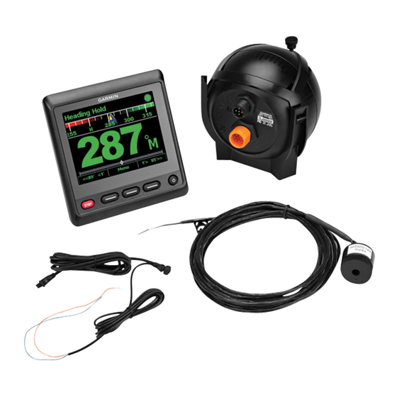
GHP™ 20 SmartPump Installation
Instructions
To obtain the best possible performance and to avoid damage
to your boat, install the Garmin
according to these instructions. Professional installation of the
autopilot system is highly recommended. Specific training in
steering systems and in marine electrical connections is
required to properly install the autopilot system.
Read all installation instructions before proceeding with the
installation. If you experience difficulty during the installation,
contact Garmin Product Support
Important Safety Information
See the Important Safety and Product Information guide in the
product box for product warnings and other important
information.
You are responsible for the safe and prudent operation of your
vessel. The autopilot is a tool that will enhance your capability to
operate your boat. It does not relieve you from the responsibility
of safely operating your boat. Avoid navigational hazards and
never leave the helm unattended.
Always be prepared to promptly regain manual control of your
boat.
Learn to operate the autopilot on calm and hazard-free open
water.
Use caution when operating the autopilot near hazards in the
water, such as docks, pilings, and other boats.
Failure to install and maintain this equipment in accordance with
these instructions could result in damage or injury.
Equipment to be connected to this product should have a fire
enclosure or be provided with a fire enclosure.
Always wear safety goggles, ear protection, and a dust mask
when drilling, cutting, or sanding.
Installation Preparation
Always wear safety goggles, ear protection, and a dust mask
when drilling, cutting, or sanding.
When drilling or cutting, always check what is on the opposite
side of the surface.
The autopilot system consists of multiple components.
Familiarize yourself with all of the component mounting and
connection considerations before beginning installation. You
must know how the components operate together in order to
correctly plan the installation on your boat.
You can consult the layout diagrams
understand the mounting and connection considerations.
Record the serial number of each component for registration
and warranty purposes
(page
Tools Needed
• Safety glasses
• Drill and drill bits
• Wrenches
September 2012
marine autopilot system
®
(page
20).
WARNING
CAUTION
CAUTION
NOTICE
(page
3) to help
20).
• 3½ in. (90 mm) hole saw
• Wire cutters/strippers
• Phillips and flat screwdrivers
• Cable ties
• Waterproof wire connectors (wire nuts) or heat shrink tubing
and a heat gun
• Marine sealant
• Marine corrosion inhibitor spray
• Portable or handheld compass (to test for magnetic
interference)
• Hydraulic hose with machine-crimped or field-replaceable
fittings that have a minimum rating of 1000 lbf/in
• Hydraulic T-fittings
• Inline hydraulic shut-off valves
• Hydraulic fluid
• Thread sealant
• Hydraulic bleeding equipment
• Anti-seize lubricant (optional)
NOTE: Mounting screws are provided for the helm control,
course computer unit (CCU), and pump. If the provided screws
are not appropriate for the mounting surface, you must provide
the correct types of screws.
Mounting and Connection Considerations
The autopilot components connect to each other and to power
using the included cables. Ensure that the correct cables reach
each component and that each component is in an acceptable
location before mounting or wiring any components.
CCU Mounting Considerations
• The course computer unit (CCU), or compass ball, must be
mounted in the forward half of the boat, no higher than 10 ft.
(3 m) above the waterline.
• The CCU (or the pump) must not be mounted in a location
where it will be submerged or exposed to wash-down.
• The CCU must not be mounted near magnetic material,
magnets (speakers and electric motors), or high-current
wires.
• The CCU must be mounted at least 24 in. (0.6 m) away from
movable or changing magnetic disturbances such as
anchors, anchor chains, wiper motors, and tool boxes.
• A handheld compass should be used to test for magnetic
interference in the area where the CCU is to be mounted.
If the handheld compass does not point north when you hold
it where you want to mount the CCU, there is magnetic
interference. Choose another location and test again.
• The CCU can be mounted below the waterline if it is not in a
location where it will be submerged or exposed to wash-
down.
• The CCU bracket must be mounted on a vertical surface or
under a horizontal surface, so the connected wires hang
straight down.
• Mounting screws are included with the CCU. You must
provide different screws if the supplied screws are not
suitable for the mounting surface.
CCU Connection Considerations
• The CCU cable connects the CCU to the pump and is 16 ft.
(5 m) long.
◦ If the CCU cannot be mounted within 16 ft. (5 m) of the
pump, replacement and extension cables are available
from your local Garmin dealer or at http://buy.garmin.com.
◦ The CCU cable must not be cut.
Alarm Mounting and Connection Considerations
• The alarm should be mounted near the primary helm station.
190-01454-02_0B
2
Printed in Taiwan
Advertisement
Table of Contents


