Garmin SL40 Pilot's Manual
Vhf comm
Hide thumbs
Also See for SL40:
- Installation manual (38 pages) ,
- User manual (24 pages) ,
- Pilot's manual (22 pages)
Table of Contents
Advertisement
Quick Links
Advertisement
Table of Contents

Related Manuals for Garmin SL40


Summary of Contents for Garmin SL40
- Page 1 SL40 VHF Comm pilot’s guide...
- Page 2 All rights reserved. Except as expressly provided herein, no part of this manual may be reproduced, copied, transmitted, disseminated, downloaded or stored in any storage medium, for any purpose without the express prior written consent of Garmin. Garmin hereby grants permission to download a single copy of this manual onto a hard drive or other electronic storage medium to be viewed and to print one copy of this manual or of any revision hereto, provided that such electronic or printed copy of this manual must contain the complete text of this copyright notice and provided further that any unauthorized commercial distribution of this manual or any revision hereto is strictly prohibited.
-
Page 3: Welcome
Our products are built to last and to allow for upgrad- ing as your needs change in the future. The SL40 is also packaged in configurations to meet the needs of customers for base station and mobile ap- plications. Contact the Garmin Customer Support for more details. -
Page 4: Contacting The Factory
Efforts made to isolate the problem Product Registration and Support Help us better support you by completing your online registration today! Have the serial number of your SL40 handy and connect to the Garmin Web site (www.garmin.com). Look for the Product Registration link on the home page. -
Page 5: Table Of Contents
EC (Emergency Channel) ......3 Sidetone Level ........... 12 MON (Monitor) ..........3 Display Brightness ..........12 RCL (Recall) ..........3 SL40 Specifications ..........13 MEM (Memory) ..........3 Features............. 13 Detailed Operation ..........4 Accessories and Packing List ....... 14 Power On/Off .......... - Page 6 Introduction Canadian RF Exposure and Compliance To ensure compliance with the RF exposure limits of Industry Canada specification RSS-102 while using the Com transmitter, the operating limitations below must be observed, unless an installation-specific evaluation has been performed according to the requirements of RSS-102. •...
-
Page 7: Getting Started
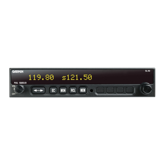
Getting Started Display Getting Started This guide describes the operation of the SL40 VHF Communication Transceiver. Display The 1-line by 16-character display is composed of 5x7 dot matrix alphanumeric high intensity LEDs. A photocell is located in the top left corner of the front panel display. The photocell automatically controls the intensity of the display from low brightness at night to high brightness during daylight operation. -
Page 8: Annunciators
Large and Small Knobs Large (outer) The dual concentric knobs on the right side of the SL40 are used to select frequencies or to view the features available within a function. Details are provided in the appropriate section. Small (inner) -
Page 9: Ec (Emergency Channel)
Getting Started Controls EC (Emergency Channel) Press the EC button to load the Emergency Channel (121.500 MHz) as the standby frequency. The Monitor function is automatically enabled. MON (Monitor) Press the MON button to listen to the standby frequency. When the active frequency receives a signal, the unit will switch automatically to the active frequency. -
Page 10: Detailed Operation
This section introduces the basic operating details of the SL40 VHF Communications Transceiver. Power On/Off Turn the Power/Volume control clockwise past the OFF detent. The SL40 may be installed to be powered from the avionics panel so the on/off control will be disabled. -
Page 11: Frequency Monitoring
Remote (REM) Frequency Abbreviations The Remote function will allow the SL40 to access the airport frequency database in an GPS receiver. Press RCL to view the Remote (REM) frequencies. Then, turn the Small, inner knob to display the 119.10 REM SLE available frequencies. -
Page 12: Auto Stack List (Lst)
Getting Started Auto Stack, User, & Weather Frequencies Auto Stack List (LST) The SL40 keeps track of the last eight Active frequencies and stores them in a stack. Duplicate fre- quencies are not stored. 119.10 LST121.80 1. Press RCL and then turn the Large, outer knob to display the Auto Stack List (LST). -
Page 13: Removing A Frequency From User Memory
Detailed Operation Removing, Replacing, & ID User Frequencies Removing a Frequency from User Memory You may edit the contents of User memory to remove its stored frequencies when you want to make a change or you receive a “MEM Full” message. Remove 121.50 1. -
Page 14: Intercom Function
The Microphone Squelch Sensitivity can be set in the System Functions. Stuck Mic The SL40 helps protect you from a situation where the microphone may get stuck in the ON or Trans- 121.50 Stuck Mic mit position. If the microphone is keyed for longer than 35 seconds, the SL40 will return to the receive Stuck Mic Message mode on the selected frequency. -
Page 15: System Functions
System Functions System Functions The SL40 includes a number of System Functions that give you more information about your com- munication equipment. Press and hold the MON button for about three seconds to reach the System Function. Turn the Large, outer knob to display the available functions. Adjustments are made with the Small, inner knob. -
Page 16: Rf Level
Detailed Operation Getting Started System Functions RF Level The RF Level function shows the relative signal strength of the frequency you are listening to. The range displayed is between 0 and 255. The value will constantly change as you are viewing it as signal RFLvl conditions change. -
Page 17: Noise Level
Detailed Operation System Functions Noise Level The Noise Level function shows the relative received noise level of the frequency you are listening NOISE to. The range displayed is between 0 and 255. The value will constantly change as you are viewing it as Noise Level signal conditions change. -
Page 18: Intercom Level
Sidetone Level Display Brightness As it arrives from the factory, the SL40 automatically adjusts its display brightness for the current lighting conditions. A small sensor at the upper left of the display is used for this function. There are two adjustments available for controlling the brightness level of the display. The first controls the lower Lo Dsp Lvl brightness level in the automatic adjustment range (Lo Dsp Lvl). -
Page 19: Sl40 Specifications
Appendix Specifications SL40 Specifications Features 760 Communication Channels Frequency Range: 118 to 136.975 MHz Active and Standby Flip/Flop Frequencies Volume Control 16-Character High-Intensity Alphanumeric LED Display Automatic Display Intensity Control Backlit Keypad Controls Transmit Status Indicator 2x8 Frequency Memory and Recall... -
Page 20: Accessories And Packing List
(www.garmin.com) and look for our Product Registration link on the home page. The SL40 display lens is coated with a special anti- reflective coating which is very sensitive to skin oils, waxes, and abrasive cleaners. It is very important... - Page 22 Fax. 503/364.2138 Garmin (Europe) Ltd. Liberty House, Bulls Copse Road, Hounsdown Business Park, Southampton, SO40 9RB, U.K. Garmin Corporation No. 68, Jangshu 2 Road, Shijr, Taipei County, Taiwan www.garmin.com Garmin AT P/N 560-0954-02 Rev. F (Garmin P/N 190-00488-00 Rev A)