Garmin 40 Pilot's Manual
Vhf comm
Hide thumbs
Also See for 40:
- Owner's manual (30 pages) ,
- Declaration of conformity (1 page) ,
- Owner's manual & reference (68 pages)
Table of Contents
Advertisement
Quick Links
Advertisement
Table of Contents

Related Manuals for Garmin 40


Summary of Contents for Garmin 40
- Page 1 SL40 VHF Comm pilot’s guide...
- Page 2 All rights reserved. Except as expressly provided herein, no part of this manual may be reproduced, copied, transmitted, disseminated, downloaded or stored in any storage medium, for any purpose without the express prior written consent of Garmin. Garmin hereby grants permission to download a single copy of this manual onto a hard drive...
-
Page 3: Welcome
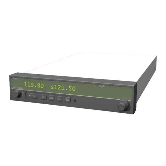
Welcome ... Welcome to a new era of aviation communication. Once again, Garmin AT, Inc. has set new standards in features and ease of use for the general aviation public. The SL40 is a VHF Communications Transceiver for use by the aviation pilot. Packaged in a new slim form factor that helps you get the most out of limited panel real estate without limiting features and performance. -
Page 4: Contacting The Factory
Help us better support you by completing your online registration today! Have the serial number of your SL40 handy and connect to the Garmin Web site (www.garmin.com). Look for the Product Registration link on the home page. Also, be sure to record your serial number in the space provided to the left. -
Page 5: Table Of Contents
Table of Contents Welcome ... i History of Revisions... i Ordering Information ... i Introduction... i Contacting the Factory ... ii Product Registration and Support ... ii Getting Started ... 1 Display ... 1 Annunciators ... 2 Controls ... 2 Power/Volume/Squelch ... - Page 6 Introduction This page intentionally left blank...
-
Page 7: Getting Started
Getting Started This guide describes the operation of the SL40 VHF Communication Transceiver. Display The 1-line by 16-character display is composed of 5x7 dot matrix alphanumeric high intensity LEDs. A photocell is located in the top left corner of the front panel display. The photocell automatically controls the intensity of the display from low brightness at night to high brightness during daylight operation. -
Page 8: Annunciators
Getting Started Annunciators and Controls TX - Transmit\ s - Standby Frequency m - Monitor Mode I - Intercom Annunciators Volume, Power, and Squelch Control Large (outer) Small (inner) knobs Flip/Flop Button Annunciators Several annunciators are used to help indicate the operating modes of your SL40. The TX (Transmit) annunciator is lighted whenever you are transmitting. -
Page 9: Ec (Emergency Channel)
EC (Emergency Channel) Press the EC button to load the Emergency Channel (121.500 MHz) as the standby frequency. The Monitor function is automatically enabled. MON (Monitor) Press the MON button to listen to the standby frequency. When the active frequency receives a signal, the unit will switch automatically to the active frequency. -
Page 10: Detailed Operation
Detailed Operation Getting Started Selecting Frequencies Volume, Power, and Squelch Control 119.80 119.80 Frequency selection with Large and Small knobs 119.80 s121.50 121.50 s119.80 Toggle Standby and Active frequencies with the Flip/Flop button Detailed Operation This section introduces the basic operating details of the SL40 VHF Communications Transceiver. Power On/Off Turn the Power/Volume control clockwise past the OFF detent. -
Page 11: Frequency Monitoring
Frequency Monitoring The Frequency Monitoring function allows you to listen to the Standby frequency, while monitoring the Active frequency for activity. Press the MON button to listen to the standby frequency. A small “m” is displayed in front of the Standby frequency. -
Page 12: Auto Stack List (Lst)
Getting Started Auto Stack, User, & Weather Frequencies 119.10 LST121.80 Viewing the Auto Stack List 119.10 MEM121.80 119.10 MEM124.55 Viewing User Stored Frequencies 119.10 WTH162.40 Viewing Weather Frequencies 162.400 MHz 162.425 MHz 162.450 MHz 162.475 MHz 162.500 MHz 162.525 MHz 162.550 MHz... -
Page 13: Removing A Frequency From User Memory
Removing a Frequency from User Memory You may edit the contents of User memory to remove its stored frequencies when you want to make a change or you receive a “MEM Full” message. 1. Press RCL. Turn the Large knob to the User (MEM) frequencies. 2. -
Page 14: Intercom Function
Detailed Operation Getting Started Intercom and Stuck Mic 119.10 *s 121.50 Intercom Function is Selected 121.50 Stuck Mic Stuck Mic Message 6. Press MEM to save the displayed ID. Turn the Large knob to “Done” and press MEM. The alphanumeric ID for a frequency is displayed only when looking at user stored frequencies using the recall (RCL) feature. -
Page 15: System Functions
System Functions The SL40 includes a number of System Functions that give you more information about your com- munication equipment. Press and hold the MON button for about three seconds to reach the System Function. Turn the Large, outer knob to display the available functions. Adjustments are made with the Small, inner knob. -
Page 16: Rf Level
Detailed Operation Getting Started System Functions RF Level The RF Level function shows the relative signal strength of the frequency you are listening to. The range displayed is between 0 and 255. The value will constantly change as you are viewing it as signal RFLvl conditions change. -
Page 17: Noise Level
Noise Level The Noise Level function shows the relative received noise level of the frequency you are listening to. The range displayed is between 0 and 255. The value will constantly change as you are viewing it as signal conditions change. Headphone Level The Headphone Level function allows you to adjust the headphone audio level. -
Page 18: Intercom Level
Appendix System Functions Intcom Lvl Intercom Level Sidton Lvl Sidetone Level Lo Dsp Lvl Hi Dsp Lvl Low and High Display Levels Intercom Level This function adjusts the Intercom Audio Level. Turn the Small knob to change the value. The range is from 0 to 255. -
Page 19: Sl40 Specifications
SL40 Specifications Features 760 Communication Channels Frequency Range: 118 to 136.975 MHz Active and Standby Flip/Flop Frequencies Volume Control 16-Character High-Intensity Alphanumeric LED Display Automatic Display Intensity Control Backlit Keypad Controls Transmit Status Indicator 2x8 Frequency Memory and Recall Stores/Recalls Eight User-Defined Frequencies (user-programmable alphanumeric naming of frequencies) Stores/Recalls Previous Eight Frequencies Frequency Monitor Function (listens to standby while monitoring the active) -
Page 20: Accessories And Packing List
Please, have the serial number of your SL40 handy, connect to our web site (www.garmin.com) and look for our Product Registration link on the home page. The SL40 display lens is coated with a special anti- reflective coating which is very sensitive to skin oils,... - Page 22 Street, Olathe, Kansas 66062, U.S.A. Garmin (Europe) Ltd. Unit 5, The Quadrangle, Abbey Park Industrial Estate, Romsey, SO51 9DL, U.K. Garmin Corporation No. 68, Jangshu 2 Road, Shijr, Taipei County, Taiwan www.garmin.com Garmin AT P/N 560-0954-02 Rev. C (Garmin P/N 190-00488-00 Rev A)