Garmin GTR 200 Installation Manual
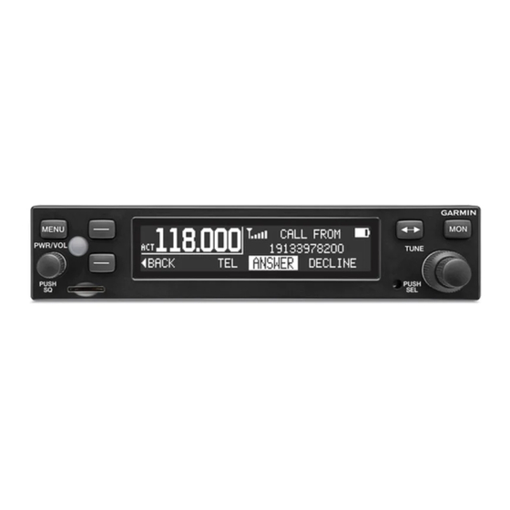
Com transceiver
Hide thumbs
Also See for GTR 200:
- Installation manual (85 pages) ,
- Pilot's manual (34 pages) ,
- Pilot's manual (30 pages)

Related Manuals for Garmin GTR 200


Summary of Contents for Garmin GTR 200
- Page 1 GTR 200 COM Transceiver Installation Manual 190-01553-00 February, 2015 Revision G...
- Page 2 Garmin. Garmin hereby grants permission to download a single copy of this manual and of any revision to this manual onto a hard drive or other electronic...
- Page 3 California to cause cancer, birth defects, or reproductive harm. This Notice is being provided in accordance with California's Proposition 65. If you have any questions or would like additional information, please refer to our web site at www.garmin.com/prop65. CAUTION The front bezel, keypad, and display can be cleaned with a microfiber cloth or with a soft cotton cloth dampened with clean water.
- Page 4 (iv) damage caused by service performed by anyone who is not an authorized service provider of Garmin; or (v) damage to a product that has been modified or altered without the written permission of Garmin. In addition, Garmin reserves the right to refuse warranty claims against products or services that are obtained and/or used in contravention of the laws of any country.
-
Page 5: Table Of Contents
4.6 Serial Data – RS-232 ....................... 4-4 4.7 MIC Audio ........................4-4 4.8 Aux Mono Audio ......................4-5 4.9 Headset Audio........................4-5 4.10 Music Inputs ........................4-5 4.11 Receiver Audio ......................4-6 190-01553-00 GTR 200 Installation Manual Rev. G Page iii... -
Page 6: Paragraph Page
A.6 Daisy Chain between Methods A and B ..............A-10 A.7 Splicing Signal Wires ....................A-10 Appendix B Serial Interface Specifications.............B-1 B.1 Electrical Interface ......................B-1 B.2 Message Formats......................B-1 Appendix C Outline and Installation Drawings ..........C-1 Appendix D Interconnect Examples ..............D-1 190-01553-00 GTR 200 Installation Manual Rev. G Page iv... - Page 7 Section 4 Connector Pinout Information............4-1 Figure 4-1 J2001 Looking at rear of unit ................4-1 Figure 4-2 CAN Bus Termination for GTR 200..............4-3 Appendix A Shield Block Connector Installation Instructions.....A-1 Figure A-1 Shield Block Install onto a Backshell .............. A-2 Figure A-2 Method A.1 for Shield Termination..............
- Page 8 Figure D-4 GTR 200- Power & Ground/GMA 240/GNS 430/aera 79X Interconnect Example ..........................D-4 Figure D-5 GTR 200- Mono Audio/Remote Mount Jack Interconnect Example ....D-5 Figure D-6 GTR 200/CAN Bus Interconnect Drawing ............D-6 Figure D-7 Dual GTR 200/GMA 240 Interconnect Drawing..........D-7 Figure D-8 GTR 200- J2001 Connector Layout ..............
- Page 9 Appendix A Shield Block Connector Installation Instructions ....A-1 Table A-1 Parts not supplied for a Shield Block Installation (Figure A-1) ......A-1 Table A-2 Shielded Cable Preparations for Garmin Connectors......... A-3 Table A-3 Shielded Cable Preparations – (Quick Term)............. A-9 Appendix B Serial Interface Specifications ............B-1...
-
Page 10: Section 1 General Description
This manual is intended to provide mechanical and electrical information for use in the planning and design of an installation of the GTR 200 into an aircraft. This manual is not a substitute for an approved airframe-specific maintenance manual, installation design drawing, or complete installation data package. -
Page 11: Technical Specifications
9.39 in (238.51 mm) backshells) GTR 200 Weight (Unit Only) 1.34 lbs (0.61 kg) GTR 200 (Installed with rack and connectors) 1.91 lbs (0.87 kg) 1.3.2 General Specifications Table 1-3 General Specifications... -
Page 12: Table 1-4 Display Specifications
Up: 10 Down: 30 1.3.4 COM Specifications The GTR 200 transmitter meets the requirements of RTCA DO-186B section 2.3 for a class 4 transmitter. Table 1-5 COM Transmitter Specifications Characteristics Specifications Two inputs, standard carbon or dynamic mic with integrated Microphone Input preamp. -
Page 13: Table 1-6 Com Receiver Specifications
The GTR 200 receiver meets the requirements of RTCA DO-186B section 2.2 for a class C receiver. Table 1-6 COM Receiver Specifications Characteristics Specifications Frequency Range 118.000 to 136.975 MHz, 25 kHz channel spacing Headset Audio Output 60 mW minimum into a 150 Ω load Audio Response Less than 6 dB of variation between 350 and 2500 Hz. -
Page 14: Certification
1.5 Reference Documents The following publications are sources of additional information for installing the GTR 200. Before installing the GTR 200, the installer should read all referenced materials along with the manual. Table 1-8 Reference Documents Part Number... -
Page 15: Section 2 Installation Overview
Careful planning and consideration of the suggestions in this section are required to achieve the desired performance and reliability from the GTR 200. The guidance of FAA advisory circulars AC 43.13-1B and AC 43.13-2B, where applicable, may be found useful for making retro-fit installations that comply with FAA regulations. -
Page 16: Installation Considerations
A COM Antenna that meets TSO-C37( ) and C38( ) or TSO-C169( ), 50W, vertically polarized with coaxial cable is recommended but not provided. 2.4.2 Installation Materials The GTR 200 is intended for use with the standard aviation accessories. The following items are required for installation, but not supplied: • Wire (MIL-W-22759/16 or equivalent) •... - Page 17 COM transceiver and COM antenna (including the GTR/ COM antenna), ELT antenna, and DF receiver antenna is critical. Use the following guidelines, in addition to others in this document, when locating the GTR 200 and its antenna.
-
Page 18: Mounting Considerations
GTR 200. The location should be such that the GTR 200 unit is not blocked by the glare shield on top, or by the throttles, control yoke, etc. on the bottom. If aircraft has a throw-over yoke, be sure the yoke does not interfere with the GTR 200. -
Page 19: Figure 2-1 Can Bus Configuration
(keeping the node lengths as short as practicable is recommended). There is no minimum node length. A GTR 200 can be connected in a G3X system that uses a GDU 37X or GDU 46X with CAN bus or RS232, the CAN bus is preferred. -
Page 20: Air Circulation And Cooling
2.8 Air Circulation and Cooling The GTR 200 unit meets all requirements without external cooling. However, as with all electronic equipment, lower operating temperatures extends equipment life. Reducing the operating temperature by 15° to 20°C (27° to 36°F) reduces the mean time between failures (MTBF). -
Page 21: Section 3 Installation Procedures
If the unit is damaged, notify the carrier and file a claim. To justify a claim, save the original shipping container and all packing materials. Do not return the unit to Garmin until the carrier has authorized the claim. -
Page 22: Backshell Assembly
Appendix C to prepare the mounting holes for the unit. You may also use the GTR 200 unit mounting rack itself as a template for drilling the mounting holes. Figure C-1 shows outline dimensions for the avionics rack for the unit. Install the rack in a... -
Page 23: Antenna Installation And Connections
3.5 Antenna Installation and Connections The GTR 200 requires a standard 50 vertically polarized antenna. Follow the antenna manufacturer’s installation instructions for mounting the antenna. The antenna should be mounted on a metal surface or a ground plane with a minimum area of 18 inches x 18 inches. -
Page 24: Post Installation Configuration And Checkout Procedures
GTR 200. Any faults or discrepancies should be corrected at this time. Remove power from the aircraft upon completion of the harness checkout. The GTR 200 can be installed after completion of the continuity and power checks. The GTR 200 should be installed into the rack and secured appropriately, as described in Section 3.4.2. -
Page 25: Figure 3-2 Configuration Mode Home Page
LIGHTING SETUP - See Section 3.6.4.6 • RS-232 STATUS - See Section 3.6.4.7 • HEADSET TESTS - See Section 3.6.5.1 • COM TESTS - See Section 3.6.5.2 • AUDIO TESTS - See Section 3.6.5.3 190-01553-00 GTR 200 Installation Manual Rev. G Page 3-5... -
Page 26: Table 3-3 Configuration Default Settings
MIN INPUT LEVEL 10%/21% Second value is lighting bus MIN BRIGHTNESS 10%/10% default LIGHTING SETUP MAX INPUT LEVEL 90%/86% MAX BRIGHTNESS 100% N/A for photocell OFF THRESHOLD OFF HYSTERESIS 0.1% BUTTON OFFSET 190-01553-00 GTR 200 Installation Manual Rev. G Page 3-6... -
Page 27: Figure 3-3 Com Setup Page
Table 3-4. For testing purposes, an “X” will appear in the appropriate TX, RX, and SQ checkboxes when the GTR 200 is transmitting, receiving, or the squelch is overridden or open (‘open’ squelch is defined as when the squelch is overridden and audio is heard). -
Page 28: Figure 3-5 Mon Swap Selection
3-5) will keep the Monitor feature ON when pressing the Frequency Transfer Key. Setting to OFF will turn off the Monitor feature when the Frequency Transfer Key is MON SWAP pressed Figure 3-5 MON Swap Selection 190-01553-00 GTR 200 Installation Manual Rev. G Page 3-8... -
Page 29: Figure 3-6 Audio Setup Page (Aux And Music Disabled)
AUX SQ. PILOT ON RIGHT Select YES or NO to select pilot location. When YES is selected the copilot is SIDE positioned to the left of the pilot for 3D audio processing. 190-01553-00 GTR 200 Installation Manual Rev. G Page 3-9... -
Page 30: Figure 3-8 Softkey Setup Page
Allows one of the softkeys to be used to cycle through stored user COM USR FREQ MEM CYCLE frequencies. *Indicates that function is not available when the intercom is set to off 190-01553-00 GTR 200 Installation Manual Rev. G Page 3-10... -
Page 31: Figure 3-9 Discrete Setup Page
COPILOT ICS KEY selection. Discrete input activates the frequency swap function (a beep tone is FREQ SWAP BTN sounded). USR FREQ CYCLE BTN Discrete input activates cycle through stored user COM frequencies. 190-01553-00 GTR 200 Installation Manual Rev. G Page 3-11... -
Page 32: Figure 3-10 Lighting Setup Page
OFFSET (default offset is 4%). Bezel backlight can brightened by raising the BUTTON OFFSET value. VIEW GRAPH Press the SMALL Knob to display the Lighting Graph (Figure 3-11). 190-01553-00 GTR 200 Installation Manual Rev. G Page 3-12... -
Page 33: Figure 3-11 Lighting Graph
The indicators next to both ‘RX’ and ‘TX’ will blink if data is being transmitted or received. The RS-232 Status page is an information only page, there are no user-selectable settings. Figure 3-12 RS-232 Status Page 190-01553-00 GTR 200 Installation Manual Rev. G Page 3-13... -
Page 34: Figure 3-13 Headset Tests Page
Make sure the headsets used for this test are set to the stereo position. A true mono headset will work correctly with the GTR 200, but only mono audio will be heard and 3D audio will not be available. The GTR 200 will detect the mono headset and automatically switch to mono operation. -
Page 35: Figure 3-14 Com Tests Page
TX AMPS – This is not a checkbox. This indicates how much current (in Amps) is supplied to the transmitter. When the GTR 200 is transmitting the current draw will be approximately 3.0 Amps under ideal load conditions. When the GTR 200 is not transmitting the current draw will be around 0.01 Amps. -
Page 36: Figure 3-15 Audio Tests Page
The Audio Tests page (Figure 3-15) and the following procedure will ensure that the audio level into the GTR 200 AUX/Music inputs (listed in Table 3-9) is set to the ideal level for best sound quality and noise rejection. It will also ensure the audio level heard in the pilot headset is at the desired level. -
Page 37: Table 3-10 Discrete Inputs
3.6.5.4 Lighting Bus Interface Check The display and bezel key backlighting on the GTR 200 can track an external lighting/dimmer bus input and use it to vary the display and bezel key backlight levels accordingly. This check is only applicable if... -
Page 38: Table 3-11 Tx Interlock Connections
1. Operate the connected serial remote tune source and the GTR 200 in normal mode. 2. Ensure that the remote source, if capable, is able to display data from the GTR 200. 3. Ensure that the remote source, if capable, is able to tune the GTR 200. - Page 39 2. Make sure the received audio from that station is clear (no background electrical noise). 3. If possible, perform the preceding steps 1 and 2 for frequencies in the high (~136.XXX MHz), mid (~127.XXX MHz), and low (~118.XXX MHz) range of the GTR 200. 190-01553-00 GTR 200 Installation Manual Rev.
-
Page 40: Unit Software
3.7.1 Checking Software Version The GTR 200 comes pre-loaded with system software. However, if the software is out of date, it is recommended that current software be loaded from a micro SD card into the GTR 200. The current software version can be displayed in normal operation mode by pressing the MENU Key, then highlighting SETUP and pressing the SMALL Knob. -
Page 41: Figure 3-18 Micro Sd Insertion
2. Download the GTR 200 System software to your PC. 3. Ensure that you have a micro SD card (Garmin recommends a Sandisk® brand 4GB micro SD card) connected to the PC in the micro SD card slot or by using an SD card adapter that allows a micro SD card to be used. -
Page 42: Continued Airworthiness
If the software on the SD card matches the software in the GTR 200 the display will show “VER X.XX UP TO DATE PLEASE REMOVE CARD”. Note that this screen (Figure 3- 20) will also be displayed following a successful software update and reboot. -
Page 43: Section 4 Connector Pinout Information
PILOT MIC IN MUSIC IN RIGHT MUSIC IN LEFT AIRCRAFT GROUND SPARE DISC 2* RS232 OUT RS232 IN CAN TERM B CAN TERM A ID LO AUX 2 LO *Indicates Active Low 190-01553-00 GTR 200 Installation Manual Rev. G Page 4-1... -
Page 44: Power
COPILOT MIC LO PILOT PTT* PILOT MIC LO MUSIC LO *Indicates Active Low 4.2 Power Pins 1 & 20 supply power to the GTR 200. Refer to drawings in Appendix D for power and ground wire gauges. Pin Name AIRCRAFT POWER AIRCRAFT GROUND 4.3 Lighting Bus... -
Page 45: Can Bus
For installations with dual GTR 200 radios, leave pin 8 open to identify the GTR200 as COM 1. Connect pin 8 to pin 27 on the second GTR 200 to identify it as COM 2. If installed, the jumper between pins 8 and 27 should be 3"... -
Page 46: Serial Data - Rs-232
4.6 Serial Data – RS-232 Section 4.6.1.1 details the formats that can be selected for the RS-232 channel. NOTE The GTR 200 can be installed into the G3X system using an RS-232 or CAN bus (preferred) connection. Pin Name RS-232 IN RS-232 OUT 4.6.1... -
Page 47: Aux Mono Audio
1.5 Vrms. The MUSIC LO must be connected to the music source along with MUSIC RIGHT and MUSIC LEFT. If MUSIC LO is not connected, music volume will be low (or inaudible), noisy, and distorted. Pin Name MUSIC IN RIGHT MUSIC IN LEFT MUSIC LO 190-01553-00 GTR 200 Installation Manual Rev. G Page 4-5... -
Page 48: Receiver Audio
*Indicates Active Low 4.13 TX Interlock TX Interlock Out is an active low output that indicates that this radio’s (GTR 200) COM is transmitting. Connect to another COM’s TX Interlock input. TX INTERLOCK OUT will sink 20mA of current and will output a voltage of 1V or less. -
Page 49: Discrete Inputs
≤375 Ω. These inputs are considered inactive if the voltage to ground is 6.5-33 VDC or the resistance to ground is >100 kΩ. Pin Name DISC 1* DISC 2* *Indicates Active Low 190-01553-00 GTR 200 Installation Manual Rev. G Page 4-7... -
Page 50: Appendix A Shield Block Connector Installation Instructions
Table A-1 list the parts needed to install a Shield Block. Parts listed in Table 2-3 supplied in the GTR 200 Connector Kit (011-003240-00). Parts listed in Table A-1 are to be provided by the installer. Table A-1 Parts not supplied for a Shield Block Installation... -
Page 51: Figure A-1 Shield Block Install Onto A Backshell
NOTE In Figure A-1, “AR” denotes quantity “As Required” for the particular installation. Figure A-1 Shield Block Install onto a Backshell 190-01553-00 GTR 200 Installation Manual Rev. G Page A-2... -
Page 52: Shield Termination Technique - Method A.1 (Standard
A.2 Shield Termination Technique – Method A.1 (Standard) 1. The appropriate number of Shield Block Backshells will be included in the particular LRU connector kit. Figure A-2 Method A.1 for Shield Termination Table A-2 Shielded Cable Preparations for Garmin Connectors Number of Window Window... - Page 53 The number of individual strands in each braid bundle is not specified. (e.g. QQB575F36T062) NOTE Flat Braid as opposed to insulated wire is specified in order to allow continuing air worthiness by allowing for visual inspection of the conductor. 190-01553-00 GTR 200 Installation Manual Rev. G Page A-4...
-
Page 54: Figure A-3 Insulation/Contact Clearance
Wire must be visible in the inspection hole after crimping and the insulation must be 1/64 – 1/32 inches from the end of the contact as shown in Figure A-3. Figure A-3 Insulation/Contact Clearance 190-01553-00 GTR 200 Installation Manual Rev. G Page A-5... - Page 55 (item 15). Warning: Placing the grooved side of the clamp across the cable bundle may risk damage to wires. 13. Attach the cover (item 16) to the backshell (item 1) using the two screws (item 17). 190-01553-00 GTR 200 Installation Manual Rev. G Page A-6...
-
Page 56: Shield Termination Technique - Method A.2 (Daisy Chain
Max” (Table A-3) length of the jacket to expose the shield. Next trim the shield so that at most 0.35 inches remains extending beyond the insulating jacket. Fold this remaining shield back over the jacket. 190-01553-00 GTR 200 Installation Manual Rev. G Page A-7... -
Page 57: Figure A-5 Method B.1 (Quick Term) For Shield Termination
Flat Braid (item 4, Figure A-5) to be attached. Teflon Heat Shrinkable Tubing: Reference the following MIL-Spec for general Teflon heat shrinkable tubing (M23053/5-X-Y) Figure A-5 Method B.1 (Quick Term) for Shield Termination 190-01553-00 GTR 200 Installation Manual Rev. G Page A-8... -
Page 58: Shield Termination-Method B.2 (Daisy Chain-Quick Term
(Figure A-6). All other restrictions and instructions for the shield termination technique set forth for Method B.1 are still applicable. NOTE The maximum length of the combined braids should be approximately 4 inches. Figure A-6 Method B.2 (Daisy Chain-Quick Term) for Shield Termination 190-01553-00 GTR 200 Installation Manual Rev. G Page A-9... -
Page 59: Daisy Chain Between Methods A And B
Splice part numbers: • Raychem D-436-36/37/38 • MIL Spec MIL-S-81824/1 This technique may be used with shield termination methods: Method A.1, Method A.2, Method B.1, and Method B.2. 190-01553-00 GTR 200 Installation Manual Rev. G Page A-10... -
Page 60: Figure A-8 D-Sub Spliced Signal Wire Illustration
Figure A-8 D-Sub Spliced Signal Wire illustration 190-01553-00 GTR 200 Installation Manual Rev. G Page A-11... -
Page 61: Appendix B Serial Interface Specifications
8-bit value 5Fh would be encoded as two characters with values of 35h and 3Fh, which map to the ASCII characters “5” and “?”, respectively. The maximum message length, including the start of message character (“$”) and the end of message <CR><LF> sequence, is 29 bytes. 190-01553-00 GTR 200 Installation Manual Rev. G Page B-1... - Page 62 Automated Surface Observing Station Class B Class C Radio Enroute Enroute Flight Advisory Service or Flight Watch Gate Helicopter Information Weather Terminal Pilot controlled lighting Multicom Radar Operations Ramp Reserved - Undefined 190-01553-00 GTR 200 Installation Manual Rev. G Page B-2...
- Page 63 Undefined B.2.2 Input Messages B.2.2.1 Set Active Frequency and Transceiver Function This message is used to set the Active frequency as well as the transceiver function. Message format (GTR 200): “GRM”.....Company identifier. “C” ....Message class. “15”....Message identifier. mk ....Active frequency: m = MHz, where m = desired MHz frequency - 30h, ranging from 118 to 136 MHz, (i.e.
- Page 64 ASCII “G”; “4” = 100 kHz/25 kHz + 30h = 4 + 30h = 34h, or an ASCII “4.” NOTE Input frequencies will be checked for validity. An RS-232 serial error message output will be generated if the frequency is invalid, or an 8.33 KHz frequency is requested. 190-01553-00 GTR 200 Installation Manual Rev. G Page B-4...
- Page 65 The GTR will ignore this message while transmitting on the active COM frequency. B.2.2.2 Set Standby Frequency and Transceiver Function This message is used to set the Standby frequency as well as the transceiver function. Message format (GTR 200): “GRM”.....Company identifier. “C” ....Message class.
- Page 66 ASCII “G”; “4” = 100 kHz/25 kHz + 30h = 4 + 30h = 34h, or an ASCII “4.” NOTE Input frequencies will be checked for validity. An RS-232 serial error message output will be generated if the frequency is invalid, or an 8.33 KHz frequency is requested. 190-01553-00 GTR 200 Installation Manual Rev. G Page B-6...
- Page 67 Remote Airport Identifier Name This message provides the airport identifier name that is used to identify to the user which airport facility that the list of frequencies is associated with. Message format (GTR 200): “GRM”.....Company identifier. “C” ....Message class. “04”....Message identifier.
- Page 68 B.2.2.4.2 Remote Airport Frequency Input This message is used to input frequency data for the specified list type. Message format (GTR 200): “GRM”.....Company identifier. “C” ....Message class. “05”....Message identifier. t ......List type: (ASCII) “0”, “1”,…, “9”. f......Frequency type (see Extended Frequency Type Enumeration).
- Page 69 All entries between nnn and the end of the table are deleted. Example message: $PGRMC18200255<chksm><CR><LF> Delete frequency lookup table entries starting from index 200 to the end of the table. 190-01553-00 GTR 200 Installation Manual Rev. G Page B-9...
- Page 70 B.2.3.1 Transceiver Status This message is used to output the current status of the transceiver. This message is sent at a 1Hz rate or whenever the transceiver status changes. Message format (GTR 200/GTR 225/GNC 255): “GRM”.....Company identifier. “C” ....Message class.
- Page 71 F = Comm failure s......Squelch test setting: (ASCII) 0 = automatic; 1 = test selected Example message: $PMRRV35G4LFR0<chksm><CR><LF> Active frequency is 119.100MHz, the standby frequency is 124.550MHz, receive function, and squelch is automatic. 190-01553-00 GTR 200 Installation Manual Rev. G Page B-11...
- Page 72 0 = input message checksum 1 = unknown message 2 = error or mismatch in message data Example message: $PGRMC051<chksm><CR><LF> Received an unknown message using company ID “GRM” and message class “C”. 190-01553-00 GTR 200 Installation Manual Rev. G Page B-12...
-
Page 73: Figure C-1 Gtr 200 Outline Drawing
CG .70 17.8 FROM 2X .05 1.3 SPACING DIMPLE 6.25 158.8 BEZEL RACK FRONT DIMPLE 4X .437 11.1 FROM FRONT OF A/C PANEL TO MOUNTING HOLES 7.00 177.8 Figure C-1 GTR 200 Outline Drawing 190-01553-00 GTR 200 Installation Manual Revision G Page C-1... -
Page 74: Appendix C Outline And Installation Drawings
211-63234-08 211-60209-09 011-00950-03 BAGGED KIT GTR200 CONNECTOR KIT 212-00018-04 011-03240-00 330-00625-37 212-20065-00 115-01879-00 117-00147-01 212-00024-04 211-63234-10 QTY 4 233-00087-00 GTR200 RACK 115-01878-00 GTR200 UNIT 011-02980-00 Figure C-2 GTR 200 Assembly Drawing 190-01553-00 GTR 200 Installation Manual Revision G Page C-2... -
Page 75: Figure C-3 Gtr 200 Installation Drawing
SPRING SNAPS INTO PLACE. TAB IN PLACE RETAINING SPRING IN PLACE RESULT SLIGHTLY DEPRESS RETAINING STEP 2 SPRING AND INSERT CONNECTOR PLATE PARALLEL TO REAR OF RACK. Figure C-3 GTR 200 Installation Drawing 190-01553-00 GTR 200 Installation Manual Revision G Page C-3... -
Page 76: Figure C-4 Gtr 200 Panel Cutout Drawing
LIP MUST BE FLUSH WITH THE FRONT OF THE AIRCRAFT PANEL .437 11.1 TYPICAL DISTANCE FROM FRONT OF PANEL TO MOUNTNG HOLES SECTION A-A Figure C-4 GTR 200 Panel Cutout Drawing 190-01553-00 GTR 200 Installation Manual Revision G Page C-4... -
Page 77: Appendix D Interconnect Examples
APPENDIX D Interconnect Examples Figure D-1 GTR 200 Interconnect Example Notes 190-01553-00 GTR 200 Installation Manual Revision G Page D-1... -
Page 78: Figure D-2 Gtr 200- Power & Ground/Intercom/Gdu 37X/46X Can Bus Interconnect Example
TIE TOGETHER TO IDENTIFY GTR AS COM 2. ID LO ID LO SEE NOTE 16. SEE NOTE 16. COM ANTENNA COM ANTENNA J2002 J2002 P2002 P2002 Figure D-2 GTR 200- Power & Ground/Intercom/GDU 37X/46X CAN Bus Interconnect Example 190-01553-00 GTR 200 Installation Manual Revision G Page D-2... -
Page 79: 190-01553-00 Gtr 200 Installation Manual
APPENDIX D Interconnect Examples Figure D-3 GTR 200- Power & Ground/Intercom/GDU 37X RS-232 Interconnect Example 190-01553-00 GTR 200 Installation Manual Revision G Page D-3... -
Page 80: Figure D-4 Gtr 200- Power & Ground/Gma 240/Gns 430/Aera 79X Interconnect Example
POWER GROUND/DATA GROUND BLACK WIRE POWER GROUND/DATA GROUND BLACK WIRE COM ANTENNA COM ANTENNA NOTE 15 NOTE 15 J2002 J2002 P2002 P2002 Figure D-4 GTR 200- Power & Ground/GMA 240/GNS 430/aera 79X Interconnect Example 190-01553-00 GTR 200 Installation Manual Revision G Page D-4... -
Page 81: Figure D-5 Gtr 200- Mono Audio/Remote Mount Jack Interconnect Example
MUSIC INPUT USING REMOTE MOUNT JACK MUSIC 1 IN LEFT NOTE 5 NOTE 5 MUSIC 1 IN RIGHT MUSIC 1 IN LO Figure D-5 GTR 200- Mono Audio/Remote Mount Jack Interconnect Example 190-01553-00 GTR 200 Installation Manual Revision G Page D-5... -
Page 82: Figure D-6 Gtr 200/Can Bus Interconnect Drawing
TIE TOGETHER TO IDENTIFY GTR AS COM 2. ID LO ID LO SEE NOTE 16. SEE NOTE 16. COM ANTENNA COM ANTENNA COM ANTENNA COM ANTENNA J2002 J2002 P2002 P2002 Figure D-6 GTR 200/CAN Bus Interconnect Drawing 190-01553-00 GTR 200 Installation Manual Revision G Page D-6... -
Page 83: Figure D-7 Dual Gtr 200/Gma 240 Interconnect Drawing
TIE TOGETHER TO IDENTIFY GTR AS COM 2. ID LO ID LO SEE NOTE 16. SEE NOTE 16. COM ANTENNA COM ANTENNA J2002 J2002 P2002 P2002 Figure D-7 Dual GTR 200/GMA 240 Interconnect Drawing 190-01553-00 GTR 200 Installation Manual Revision G Page D-7... -
Page 84: Figure D-8 Gtr 200- J2001 Connector Layout
AUDIO LO HS LO IN 1 MIC C LO J2001 AS VIEWED LOOKING AT REAR OF UNIT J2001 AS VIEWED LOOKING AT REAR OF UNIT Figure D-8 GTR 200- J2001 Connector Layout 190-01553-00 GTR 200 Installation Manual Revision G Page D-8...