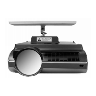
Sharp XG-PH50X Installation Instructions Manual
Ceiling mounting bracket
Hide thumbs
Also See for XG-PH50X:
- Operation manual (109 pages) ,
- Quick start reference sheet (6 pages) ,
- Brochure & specs (4 pages)
Advertisement
Quick Links
Advertisement

Related Manuals for Sharp XG-PH50X


Summary of Contents for Sharp XG-PH50X
- Page 1 AN-PHCM20 INSTALLATION INSTRUCTIONS MOUNTING BRACKET FOR USE ONLY WITH SHARP PROJECTOR MODEL XG-PH50X CEILING MOUNTING BRACKET AN-PHCM20 CEILING MOUNTING BRACKET COMBINED WITH OPTIONAL ADJUSTABLE EXTENSION TUBE MODEL AN-EP101B COPYRIGHT © 2005 SHARP ELECTRONICS CORPORATION...
- Page 2 BUILDING AND SAFETY CODES. SAVE THIS BOOKLET AFTER THE INSTALLATION COMPLETED. THE ACCESSORIES REFERRED TO IN THESE INSTRUCTIONS INTENDED FOR USE ONLY WITH COMPATIBLE SHARP PROJECTORS. SEE SHARP PROJECTOR OWNER’S MANUAL OR SHARP DEALER TO DETERMINE CAUTION: THE BRACKET MOUNTING SCREWS MUST GO DIRECTLY INTO THE BEAMS.
- Page 3 LOCATION OF THE CEILING BRACKET Please refer to the owner’s manual for your SHARP LCD PROJECTOR for information which will help you to determine the best location for the placement of the ceiling mounting bracket assembly.
- Page 4 INSTALLATION INSTRUCTIONS CEILING BRACKET AN-PHCM20 Select straddle beam or single beam installation. Use the ceiling bracket as a template to mark the location where the pilot holes should be drilled. Drill the pilot holes for the support screws using a 1/8” drill bit into the center of the beam.
- Page 5 Select the contour appropriate for your application and cut out the opening along the line indicated on the label. Use a very sharp cutting tool. Thread the cable through the plastic trim cover. Place the plastic trim cover in place over the ceiling plate and press the velcro tabs together.
- Page 6 INSTALLATION INSTRUCTIONS CEILING BRACKET AN-PHCM20 STEP 3 DETACH THE POSITIONING ASSEMBLY FROM THE PROJECTOR ATTACHMENT PLATE. NOTE: PLEASE LOOK OVER THE EXACT MANNER IN WHICH THE FIGURE 5 POSITIONING ASSEMBLY AND THE ATTACHMENT PLATE GO TOGETHER SO THAT YOU WILL BE ABLE TO REASSEMBLE THEM POSITIONING KNUCKLE ASSEMBLY WHEN YOU HANG THE PROJECTOR.
- Page 7 INSTALLATION INSTRUCTIONS CEILING BRACKET AN-PHCM20 STEP 5 ATTACH THE POSITIONING ASSEMBLY TO THE CEILING PLATE FIGURE 8 WASHER LOCKING NUT UPPER KNUCKLE IF YOU INTEND TO RUN AUDIO OR VIDEO CABLES THROUGH THE CEILING PLATE PROCEED WITH STEP 5.1 AND 5.2, OTHERWISE PROCEED TO STEP 5.3: Cut opening in the ceiling plate trim cover as indicated on the label inside cover near the center bushing.
-
Page 8: Installation Instructions
The ceiling plate and the projector attachment plate of this center hole in lock base. model mounting bracket kit are equipped with attachment facilities that enable the use of a SHARP Model AN-CMCSS16 or AN-CMCSS46 theft Anti-spin hole aligns with prevention security cable optional accessory. -
Page 9: Horizontal Tilt Adjustment
It will curve back by its own spring action to wrap around itself enough to close the gap. (See Fig. 12) 8.3 If the projector is hung at a sharp angle, you may trim the collar for a better fit. (See Fig. 13) FIGURE 12 FIGURE 13 DO NOT RUN THE AC POWER CORD INSIDE THE PLASTIC TRIM COLLAR. - Page 10 INSTALLATION INSTRUCTIONS CEILING BRACKET AN-PHCM20 DIMENSIONS AND MEASUREMENTS OF COMPONENTS FOR SHARP MOUNTING BRACKET AN-MBCM10 CEILING PLATE 4” WIDE X 18” LONG DISTANCE BETWEEN SETS OF MOUNTING HOLES: 1st SET 12”, 2nd SET 14”, 3rd SET 16” ADDITIONAL POSSIBLE COMBINATIONS OF MOUNTING HOLE DISTANCE 13” & 15”...
-
Page 11: One-Year Limited Warranty
In no event shall SHARP be liable, or in any way responsible, for any damages or defects in the Product which were caused by repairs or attempted repairs performed by anyone other than SHARP. - Page 12 COPYRIGHT © 2005 SHARP ELECTRONICS CORPORATION...
- Page 13 SUPPLEMENTAL INSTRUCTIONS FOR INSTALLATION OF 2” EXTENSIONS TO LOWER MOUNTING BRACKET FROM CEILING. CEILING PLATE COVER INSTALL ONE 2” EXTENSION OR TWO 2” EXTENSIONS HERE AS NEEDED. CONTINUE WITH STEP 5 OF THE INSTALLATION INSTRUCTIONS. COPYRIGHT © 2005 SHARP ELECTRONICS CORPORATION...