Chamberlain LA500 Installation Manual
Elite series vehicular swing gate operator
Hide thumbs
Also See for LA500:
- Installation manual (60 pages) ,
- Manual (1 page) ,
- Technical information (1 page)
Table of Contents
Advertisement
Quick Links
LA500 & LA500-S
VEHICULAR SWING GATE OPERATOR
I N S T A L L A T I O N M A N U A L
Your model may look different than the model illustrated in this manual.
THIS PRODUCT IS TO BE
INSTALLED AND SERVICED BY
A TRAINED GATE SYSTEMS
TECHNICIAN ONLY.
Visit www.liftmaster.com to
locate a professional installing
dealer in your area.
UL325
compliant
This model is for use on vehicular
passage gates ONLY and not
intended for use on pedestrian
passage gates.
This model is intended for use in
Class I, II, III and IV vehicular swing
gate applications.
UL991
compliant
Advertisement
Table of Contents
Troubleshooting

Related Manuals for Chamberlain LA500


Summary of Contents for Chamberlain LA500
- Page 1 LA500 & LA500-S VEHICULAR SWING GATE OPERATOR I N S T A L L A T I O N M A N U A L Your model may look different than the model illustrated in this manual. THIS PRODUCT IS TO BE...
-
Page 3: Table Of Contents
LiftMaster Internet Gateway ........ -
Page 4: Ul325 Model Classifications
SAFETY UL325 MODEL CLASSIFICATIONS UL325 MODEL CLASSIFICATIONS CLASS I – RESIDENTIAL VEHICULAR GATE OPERATOR A vehicular gate operator (or system) intended for use in a home of one-to four single family dwellings, or a garage or parking area associated therewith. CLASS II –... -
Page 5: Safety Installation Information
SAFETY SAFETY INSTALLATION INFORMATION SAFETY INSTALLATION INFORMATION 1. Vehicular gate systems provide convenience and security. Gate systems are 8. Controls intended for user activation must be located at least 6 feet (1.8 m) comprised of many component parts. The gate operator is only one away from any moving part of the gate and where the user is prevented component. -
Page 6: Gate Construction Information
SAFETY GATE CONSTRUCTION INFORMATION GATE CONSTRUCTION INFORMATION Vehicular gates should be installed in accordance with ASTM F2200: Standard Specification for Automated Vehicular Gate Construction. For a copy, contact ASTM directly at 610-832-9585 or www.astm.org. GENERAL REQUIREMENTS 3.1.3 A gap, measured in the horizontal plane parallel to the roadway, between a fixed stationary object nearest the roadway, (such as a gate support post) Gates shall be constructed in accordance with the provisions given for the and the gate frame when the gate is in either the fully open position or the... -
Page 7: Required Entrapment Protection Devices
SAFETY REQUIRED ENTRAPMENT PROTECTION DEVICES REQUIRED ENTRAPMENT PROTECTION DEVICES To prevent SERIOUS INJURY or DEATH from a moving gate: • Entrapment protection devices MUST be installed to protect anyone who may • Locate entrapment protection devices to protect between moving gate and come near a moving gate. -
Page 8: Important Safety Information
SAFETY IMPORTANT SAFETY INFORMATION IMPORTANT SAFETY INFORMATION INSTALLATION To prevent SERIOUS INJURY or DEATH from a moving gate: • Pinch points must be guarded at all times. Install enclosed-style gate tracks and • Entrapment protection devices MUST be installed to protect anyone who may roller guards. -
Page 9: Important Safety Information
• To reduce the risk of FIRE or INJURY to persons use ONLY LiftMaster part • ALWAYS keep people and objects away from the gate. NO ONE SHOULD CROSS 29-NP712 for replacement batteries. -
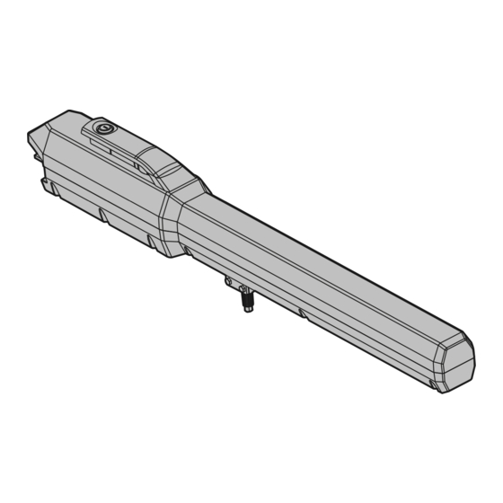
Page 10: Introduction
4.21" (10.7 cm) 5.83" (14.8 cm) Gate Bracket Post Bracket Warning Signs (2) and Warranty Card Operator Model LA500 (1) Model LA500-S (2) 40.35" (102.5 cm) Key (2) Standard Control Box with Batteries 12 Vdc 7AH (2) Large Metal Control Box (XLM),... -
Page 11: Features
INTRODUCTION FEATURES FEATURES OPERATOR FEATURES • Advanced “Centerpiece” Control Board • Manual - Secure power failure selection • EMI AC Power Surge Protection and Filter Board • SAMS compatible - Main AC voltage input selection: 120 Vac (factory setting) or 240 Vac (field •... -
Page 12: Preparation
PREPARATION SITE PREPARATION Check the national and local building codes BEFORE installation. SAFETY Entrapment protection devices are required to protect against any entrapment or safety conditions encountered in your gate application (refer to page 5 for more details). Install warning signs on both sides of the gate. Warning Signs Entrapment Danger VEHICLE LOOPS... - Page 13 SITE PREPARATION INSTALLATION TYPES Identify your installation type. The installation steps in this manual will show a typical Pull-to-Open application. PUSH-TO-OPEN PULL-TO-OPEN Post Install Column Install Post Install Column Install Gate Hinge Gate Hinge Gate Hinge Gate Hinge Heavy Steel Plate for Reinforcement (Not provided) Heavy Steel Plate...
-
Page 14: Mounting Options
PREPARATION MOUNTING OPTIONS MOUNTING OPTIONS MOUNTING DOs Weld a horizontal bar across entire gate on any installation for strength. The operator can be mounted on top of the gate frame. Make sure that the operator is mounted level or it will not function properly. MOUNTING DON'Ts An off-level installation may cause the gate or operator to fail prematurely. -
Page 15: Installation
INSTALLATION MANUAL RELEASE + DETERMINE THE POSITION OF THE POST BRACKET MANUAL RELEASE Insert the key into the lock and turn it 180 degrees counterclockwise. Turn the release lever 180 degrees counterclockwise. The operator is now in manual mode. If this operator is a replacement for a Miracle-One™ operator, use the existing post bracket and gate bracket. Remove the Miracle-One™ operator from the brackets and proceed to page 15. -
Page 16: Determine The Position Of The Gate Bracket
INSTALLATION DETERMINE THE POSITION OF THE GATE BRACKET + WELD THE BRACKETS DETERMINE THE POSITION OF THE GATE BRACKET The gate bracket MUST be installed in an area that can withstand heavy forces. Additional reinforcement steel plates may be necessary for mounting. Position a level on the post bracket and measure 27.75 inches over from the center of the gate hinge point and mark the location on the gate. -
Page 17: Attach The Operator To The Brackets
INSTALLATION ATTACH THE OPERATOR TO THE BRACKETS ATTACH THE OPERATOR TO THE BRACKETS Attach the operator to the post bracket with the bolt, mounting plate, and nut as shown. Attach the operator to the gate bracket with the bolt, washer, and nut as shown. Tighten the nut until it reaches the bottom of the gate bracket, then turn the nut a half turn, making sure not to overtighten. -
Page 18: Standard Control Box
INSTALLATION STANDARD CONTROL BOX For Large Metal Control Box installation, refer to the following page. STANDARD CONTROL BOX MOUNT THE CONTROL BOX Expansion Board The control box MUST be mounted within 5 feet (1.52 m) of the gate operator. Mount the control box as high as possible for best radio reception. Make sure the control box is level. -
Page 19: Large Metal Control Box (Xlm)
INSTALLATION LARGE METAL CONTROL BOX (XLM) LARGE METAL CONTROL BOX (XLM) MOUNT THE CONTROL BOX (XLM) The control box MUST be mounted within 5 feet (1.52 m) of the gate operator. Mount the control box as high as possible for best radio reception. Make sure the control box is level. -
Page 20: Wiring
WIRING WIRE THE ENTRAPMENT PROTECTION DEVICES + EARTH GROUND ROD WIRE THE ENTRAPMENT PROTECTION DEVICES Entrapment protection devices are required. Refer to page 5 for more information regarding application. To prevent SERIOUS INJURY or DEATH from a moving gate: • Entrapment protection devices MUST be installed to protect anyone who may •... -
Page 21: Wire The Operator Arm To The Control Board
WIRING WIRE THE OPERATOR TO THE CONTROL BOARD WIRE THE OPERATOR ARM TO THE CONTROL BOARD Insert the operator cable through the watertight connector mounted in the bottom of the control box. Extend the operator cable and wires to the Gate 1 connector and connect as shown. -
Page 22: Dual Gates Only
WIRING DUAL GATES ONLY DUAL GATES ONLY INSTALL THE EXTENSION CABLE AND JUNCTION BOX Before digging, contact local underground utility locating companies. The following items are required to complete the junction box installation: • 4 x 4 Junction Box with 3/4" NPT threaded port holes •... -
Page 23: Dual Gates Only
WIRING DUAL GATES ONLY DUAL GATES ONLY WIRE THE EXTENSION CABLE TO THE CONTROL BOARD Choose a knockout in the bottom of the control box. Extension Cable Insert a watertight connector through the knockout and tighten with nut. Insert the extension cable through watertight connector. SO AR / CHARGER BRO GRN WHT YEL BLU RED... -
Page 24: Power Wiring
WIRING POWER WIRING POWER WIRING NUMBER OF CYCLES PER DAY This operator can be wired for either 120 Vac (standard) or a solar Swing Gate Installation (6 ft. 1200 lb. gate/ 19 ft. 500 lb. gate) panel (not provided). Follow the directions according to your application. ACCESSORY SINGLE GATE DUAL GATE... -
Page 25: Connect Batteries
10W solar panels in series and two 7AH batteries are recommended. For Zone 3 cold weather sites, two 33AH batteries are recommended (for Large Metal Control Box (XLM) ONLY). We recommend LiftMaster low power draw accessories to minimize 20W SOLAR PANEL power draw, refer to accessory page. -
Page 26: Engage The Operator
WIRING CONNECT BATTERIES + ENGAGE THE OPERATOR CONNECT BATTERIES The batteries are charged in the circuit by the transformer or solar panel. LARGE METAL CONTROL BOX (XLM) 7AH BATTERIES Turn OFF AC power to the operator at the circuit breaker and unplug the transformer. -
Page 27: Adjustment
ADJUSTMENT LIMIT AND FORCE ADJUSTMENT LIMIT AND FORCE ADJUSTMENT To reduce the risk of SEVERE INJURY or DEATH: • Without a properly installed safety reversal system, persons (particularly small • NEVER use force adjustments to compensate for a binding or sticking gate. children) could be SERIOUSLY INJURED or KILLED by a moving gate. -
Page 28: Obstruction Test
ADJUSTMENT LIMIT AND FORCE ADJUSTMENT + OBSTRUCTION TEST FINE TUNE THE FORCE The FORCE DIAL on the control board is used for fine tuning the force in cases where wind or environmental changes may affect the gate travel. TEST BUTTONS Based on the length and weight of the gate it may be necessary to make additional TWORK force adjustments. -
Page 29: Programming
PROGRAMMING REMOTE CONTROLS (NOT PROVIDED) + ERASE ALL CODES REMOTE CONTROLS (NOT PROVIDED) A total of 50 Security✚ 2.0™ remote controls and 2 keyless entries (1 PIN for each LEARN keyless entry) can be programmed to the operator. NOTE: When the memory is full the operator will exit programming mode and the remote control/keyless entry will XMITTER not be programmed. -
Page 30: Operation
When gate is in the closed position, activation of the remote control button will open LiftMaster remote control or SINGLE BUTTON on the control board will close the gate the gate. During the open cycle another activation of the remote control will stop the and return the operator to normal operation. -
Page 31: Maintenance
LiftMaster Internet Gateway will pair to the operator if it is within range and the operator will beep if programming is successful. The status as shown by the LiftMaster Internet Gateway app will be either “open” or “closed”. The gate operator can then be controlled through the LiftMaster Internet Gateway app. -
Page 32: Control Board Overview
ADDITIONAL FEATURES CONTROL BOARD OVERVIEW CONTROL BOARD OVERVIEW SET OPEN Button The SET OPEN button sets the OPEN limit. See Adjust Limits section. SET CLOSE Button The SET CLOSE button sets the CLOSE limit. See Adjust Limits section. MOVE GATE Button The MOVE GATE buttons will either open or close the gate when the operator is in Limit setting mode. -
Page 33: Accessory Features On Control Board
ADDITIONAL FEATURES ACCESSORY FEATURES ON CONTROL BOARD ACCESSORY FEATURES ON CONTROL BOARD Single Button Control, SBC Gate command sequence - Open, Stop, Close, Stop, ... Soft open (maintained switch does not override external safeties and does not reset alarm condition) (2 terminals) Fire Dept Open Input Acts as hard open. -
Page 34: Expansion Board Overview
ADDITIONAL FEATURES EXPANSION BOARD OVERVIEW EXPANSION BOARD OVERVIEW To AVOID damaging the circuit board, relays or accessories, DO NOT connect more than 42 Vdc (32 Vac) to the AUX relay contact terminal blocks. QUICK CLOSE Switch OFF: No change to the gate's normal operation. ON: When CLOSE EYES/Interrupt loop is deactivated it causes an opening or a stopped gate to close (ignores the Timer-to-Close). -
Page 35: Accessory Features On Expansion Board
ADDITIONAL FEATURES ACCESSORY FEATURES ON EXPANSION BOARD ACCESSORY FEATURES ON EXPANSION BOARD Open Input (& common) Open command - opens a closed gate. Soft close (maintained switch does not override external safeties and does not reset alarm condition) (3-Button Control Station, If maintained, pauses Timer-to-Close at OPEN limit. -
Page 36: Gate Operator Setup Examples
ADDITIONAL FEATURES GATE OPERATOR SETUP EXAMPLES GATE OPERATOR SETUP EXAMPLES The following are example setups for the gate operator. Your specific site requirements may be different. Always setup the operator system to the site requirements, including all necessary secondary entrapment protection systems. RESIDENTIAL SMALL One to four residential homes sharing a gated entrance/exit, allowing vehicle access trumps security concerns A residential community (more than four homes) having one or more gated entrances/exits, allowing vehicle access trumps security concerns... -
Page 37: Limit Setup With A Remote Control
ADDITIONAL FEATURES LIMIT SETUP WITH A REMOTE CONTROL LIMIT SETUP WITH A REMOTE CONTROL To set the limits using a remote control, first you will need a 3-button remote control that has been programmed for OPEN, CLOSE, and STOP. Refer to the Programming section. -
Page 38: Troubleshooting
TROUBLESHOOTING CONTROL BOARD LEDS CONTROL BOARD LEDS The control board is equipped with many LEDs that have a variety of functions. The control board LEDs indicate the status of the operator, assist with programming, and diagnose potential problems with the operator. NOTE: When cycling or disconnecting power (ac/dc) to the control board, it is recommended that you unplug the J15 and Solar/Charger plug. - Page 39 TROUBLESHOOTING CONTROL BOARD LEDS CONTROL BOARD LEDS DIAGNOSTIC CODES LEDS YELLOW DIAGNOSTIC LED RED DIAGNOSTIC LED # BLINKS MEANING CORRECTION BEFORE replacing the control board cycle the power first. If the problem persists, then proceed with the appropriate correction. 1 BLINK Low Power Mode (not an error) # BLINKS...
-
Page 40: Troubleshooting Chart
TROUBLESHOOTING TROUBLESHOOTING CHART FAULT POSSIBLE CAUSES CORRECTIONS Operator does not a) No power to control board a) Check AC and battery power run and diagnostic b) Open fuse b) Check fuses LED not on. c) If on battery power only, low or dead batteries c) Charge batteries by AC or solar power or replace batteries d) Defective control board d) Replace defective control board... - Page 41 TROUBLESHOOTING TROUBLESHOOTING CHART FAULT POSSIBLE CAUSES CORRECTIONS Gate stops during a) Check DIAGNOSTIC LEDs a) Use Diagnostic code to identify issue travel and reverses b) Inherent force obstruction detection b) Check for obstruction in gate’s path or travel. Remove arm from gate and move gate immediately.
- Page 42 TROUBLESHOOTING TROUBLESHOOTING CHART FAULT POSSIBLE CAUSES CORRECTIONS Obstruction in gates a) Force setting too high a) Adjust force setting. Retest that obstruction in gate’s path causes gate to stop and reverse direction. path does not cause gate to stop and reverse Photoelectric sensor a) Incorrect photoelectric sensor wiring...
-
Page 43: Troubleshooting Chart
TROUBLESHOOTING TROUBLESHOOTING CHART FAULT POSSIBLE CAUSES CORRECTIONS Accessories a) Accessory power protector active a) Disconnect all accessory powered devices and measure accessory power voltage (should connected to be 23 – 30 Vdc). If voltage is correct, connect accessories one at a time, measuring b) Defective control board accessory voltage after every new connection. -
Page 44: Wiring Diagrams
WIRING DIAGRAMS STANDARD CONTROL BOX Field Wiring Field Wiring To protect against fire and electrocution: • DISCONNECT power and battery BEFORE installing or servicing operator. For continued protection against fire: Edge • Replace ONLY with fuse of same type and rating. -
Page 45: Large Metal Control Box (Xlm)
WIRING DIAGRAMS LARGE METAL CONTROL BOX (XLM) Field Wiring Field Wiring To protect against fire and electrocution: • DISCONNECT power and battery BEFORE installing or servicing operator. For continued protection against fire: Edge • Replace ONLY with fuse of same type and rating. -
Page 46: Accessories
REMOTE CONTROLS application. Up to four solar panels can be connected to the Chamberlain offers a variety of LiftMaster remote controls to satisfy your application needs. operator. Single-button to 4-button, visor or key chain. The following remote controls are compatible Model SOLPNL10W12V (requires 2 minimum) with operators manufactured by Chamberlain after 1993. -
Page 47: Repair Parts
REPAIR PARTS STANDARD CONTROL BOX GATE OPERATOR ARM ITEM PART NUMBER DESCRIPTION ITEM PART NUMBER DESCRIPTION K74-34582-1 Standard Plastic Control Box Only LA500 Primary Arm K76-36296-1 Outlet KSWG-0623 Rear Connector with Pin K75-36635 Control Board Bracket 41ASWG-0119 Release Keys K1D7545CC... -
Page 48: Warranty
The Chamberlain Group, Inc. (“Seller”) warrants to the first purchaser of this product, for the structure in which this product is originally installed, that it is free from defect in materials and/or workmanship for a period of 3 year residential/ 2 year commercial from the date of purchase [and that the LA500™ and LA500CONT™ are free from defect in materials and/or workmanship for a period of 3 year residential/ 2 year commercial from the date of purchase].