Table of Contents
Advertisement
Advertisement
Table of Contents

Related Manuals for Asus F1A75-M PRO R2.0


Summary of Contents for Asus F1A75-M PRO R2.0
- Page 1 F1A75-M PRO R2.0...
- Page 2 Product warranty or service will not be extended if: (1) the product is repaired, modified or altered, unless such repair, modification of alteration is authorized in writing by ASUS; or (2) the serial number of the product is defaced or missing.
-
Page 3: Table Of Contents
Contents Safety information ...................... vi About this guide ......................vii F1A75-M PRO R2.0 specifications summary ............ix Package contents ...................... xii Chapter 1: Product introduction Special features .................... 1-1 1.1.1 Product highlights ................1-1 1.1.2 Digital Power Design: The New Standard ........1-2 1.1.3... - Page 4 Managing and updating your BIOS ............. 2-1 2.1.1 ASUS Update utility ................ 2-1 2.1.2 ASUS EZ Flash 2 ................2-2 2.1.3 ASUS CrashFree BIOS 3 utility ............2-3 2.1.4 ASUS BIOS Updater ............... 2-4 BIOS setup program ..................2-6 Main menu ....................2-10 2.3.1 System Language [English] ............
- Page 5 2.7.8 Boot Option Priorities ..............2-26 2.7.9 Boot Override ................2-26 Tools menu ....................2-27 2.8.1 ASUS EZ Flash 2 Utility ..............2-27 2.8.2 ASUS O.C. Profile ................. 2-27 2.8.3 ASUS SPD Information ..............2-27 Exit menu ....................2-28 Appendices Notices ........................
-
Page 6: Safety Information
Safety information Electrical safety • To prevent electrical shock hazard, disconnect the power cable from the electrical outlet before relocating the system. • When adding or removing devices to or from the system, ensure that the power cables for the devices are unplugged before the signal cables are connected. If possible, disconnect all power cables from the existing system before you add a device. -
Page 7: About This Guide
Refer to the following sources for additional information and for product and software updates. ASUS websites The ASUS website provides updated information on ASUS hardware and software products. Refer to the ASUS contact information. Optional documentation Your product package may include optional documentation, such as warranty flyers, that may have been added by your dealer. -
Page 8: Conventions Used In This Guide
Conventions used in this guide To ensure that you perform certain tasks properly, take note of the following symbols used throughout this manual. DANGER/WARNING: Information to prevent injury to yourself when trying to complete a task. CAUTION: Information to prevent damage to the components when trying to complete a task IMPORTANT: Instructions that you MUST follow to complete a task. -
Page 9: F1A75-M Pro R2.0 Specifications Summary
DDR3 2250(O.C.)/1866/1600/1333/1066 MHz memory modules * The maximum 64GB memory capacity can be supported with 16GB or above DIMMs. ASUS will update the memory QVL once the DIMMs are available in the market. ** Refer to www.asus.com for the latest Memory QVL (Qualified Vendors List). - Page 10 ASUS Exclusive Features - ASUS Network iControl* featuring instant network bandwidth domination for top network program in use - ASUS USB 3.0 Boost featuring the latest USB 3.0 UASP standard - MemOK! - ASUS AI Suite II - AI Charger+...
- Page 11 F1A75-M PRO R2.0 specifications summary Back Panel I/O ports 1 x PS/2 keyboard / mouse combo port 1 x HDMI output port 1 x DVI-D output port 1 x D-Sub output port 1 x Optical S/PDIF output port 1 x LAN (RJ-45) port 2 x USB 2.0/1.1 ports...
-
Page 12: Package Contents
USB34 USB56 CLRTC COM1 AAFP PANEL 2 x Serial ATA 6.0 Gb/s ASUS F1A75-M PRO R2.0 motherboard cables 1 x Q-Shield User Guide Support DVD • If any of the above items is damaged or missing, contact your retailer. •... -
Page 13: Chapter 1: Product Introduction
Complete USB 3.0 integration Double USB Access, Double Convenience ASUS facilitates strategic USB 3.0 accessibility for both the front and rear panels - 6 USB 3.0 ports in total. Experience the latest plug & play connectivity at speeds up to 10 times faster than USB 2.0. -
Page 14: Digital Power Design: The New Standard
The Ultimate Turbo Processor Unleash your performance with ASUS’ simple onboard switch or AI Suite II utility. The TPU chip offers precise voltage control and advanced monitoring through Auto Tuning and TurboV functions. Auto tuning offers a user friendly way to automatically optimize the system for fast, yet stable clock speeds, while TurboV enables unlimited freedom to adjust APU Multiplier for optimized performance in diverse situations. -
Page 15: Asus Exclusive Features
POST situations. ASUS TurboV Feel the adrenaline rush of real-time OC-now a reality with the ASUS TurboV. This easy OC tool allows you to overclock without exiting or rebooting the OS; and its user-friendly interface makes overclock with just a few clicks away. Moreover, the ASUS OC profiles in TurboV provides the best O.C. -
Page 16: Fan Xpert
Electronic Magnetic Interference (EMI). ASUS EZ Flash 2 ASUS EZ Flash 2 is a user-friendly utility that allows you to update the BIOS without using a bootable floppy disk or an OS-based utility. ASUS MyLogo2™... -
Page 17: Before You Proceed
The motherboard is European Union´s Energy-related Products (ErP) ready, and ErP requires products to meet certain energy efficiency requirements in regards to energy consumptions. This is in line with ASUS vision of creating environment-friendly and energy- efficient products through product design and innovation to reduce carbon footprint of the product and thus mitigate environmental impacts. -
Page 18: Motherboard Overview
Place eight screws into the holes indicated by circles to secure the motherboard to the chassis. DO NOT overtighten the screws! Doing so can damage the motherboard. Place this side towards the rear of the chassis. F1A75-M PRO R2.0 Chapter 1: Product introduction... -
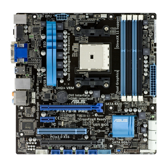
Page 19: Motherboard Layout
_HDMI ELED740 ELED730 MemOK! DRAM_LED USB3_12 LAN1_USB12 AUDIO Lithium Cell CMOS Power 477D PCIEX16_1 F1A75-M PRO R2.0 8111F SB_PWR PCIEX1_1 Super ® PCI1 PCIEX16_2 64Mb BIOS SPDIF_OUT USB3_56 USB78 USB910 USB34 USB56 CLRTC COM1 AAFP PANEL ASUS F1A75-M PRO R2.0... -
Page 20: Layout Contents
Ensure that you use a APU designed for the FM1 socket. The APU fits in only one correct orientation. DO NOT force the APU into the socket to prevent bending the pins and damaging the APU! F1A75-M PRO R2.0 F1A75-M PRO R2.0 CPU socket FM1 Chapter 1: Product introduction... -
Page 21: Apu Installation
1.4.1 APU installation ASUS F1A75-M PRO R2.0... -
Page 22: Apu Heatsink And Fan Assembly Installation
1.4.2 APU heatsink and fan assembly installation Apply the Thermal Interface Material to the APU heatsink and APU before you install the heatsink and fan if necessary. To install the APU heatsink and fan assembly Chapter 1: Product introduction 1-10... - Page 23 To uninstall the APU heatsink and fan assembly ASUS F1A75-M PRO R2.0 1-11...
-
Page 24: System Memory
The figure illustrates the location of the DDR3 DIMM sockets: Channel Sockets Channel A DIMM_A1 and DIMM_A2 Channel B DIMM_B1 and DIMM_B2 F1A75-M PRO R2.0 F1A75-M PRO R2.0 240-pin DDR3 DIMM sockets Chapter 1: Product introduction 1-12... -
Page 25: Memory Configurations
• The maximum 64GB memory capacity can be supported with 16GB or above DIMMs. ASUS will update the memory QVL once the DIMMs are available in the market. • The default memory operation frequency is dependent on its Serial Presence Detect (SPD), which is the standard way of accessing information from a memory module. - Page 26 F1A75-M PRO R2.0 Motherboard Qualified Vendors Lists (QVL) DDR3 2250 (O.C.) MHz capability DIMM socket support Chip (Optional) Vendors Part No. Size SS/DS Chip NO. Timing Voltage Brand 1 DIMM 2 DIMMs 4 DIMMs KINGSTON KHX2250C9D3T1K2/4GX(XMP) 4GB ( 2x 2GB ) DS 1.65V...
- Page 27 • OCZ3G16004GK 4GB(2 x 2GB) 8-8-8-24 1.7V • • • OCZ3OB1600LV4GK 4GB(2 x 2GB) 1.65V • • • OCZ3G1600LV6GK 6GB(3 x 2GB) 8-8-8-24 1.65V • • Super WA160UX6G9 6GB(3 x 2GB) • • • Talent ASUS F1A75-M PRO R2.0 1-15...
- Page 28 DDR3 1333 MHz capability DIMM socket support Chip (Optional) Vendors Part No. Size Chip NO. Timing Voltage Brand 1 DIMM 2 DIMMs 4 DIMMs A-Data AD63I1B0823EV SS A-Data 3CCA-1509A • • • 1.25V- A-Data AXDU1333GC2G9-2G(XMP) 4GB(2 x 2GB) SS - 9-9-9-24 1.35V(low •...
- Page 29 A1 and B1 for better compatibility. • 4 DIMMs: Supports four (4) modules inserted into both the blue and black slots as two pairs of Dual-channel memory configuration. Visit the ASUS website at www.asus.com for the latest QVL. ASUS F1A75-M PRO R2.0 1-17...
-
Page 30: Installing A Dimm
1.5.3 Installing a DIMM To remove a DIMM Chapter 1: Product introduction 1-18... -
Page 31: Expansion Slots
This motherboard supports PCI Express x1 network cards, SCSI cards, and other cards that comply with the PCI Express specifications. 1.6.5 PCI Express x16 slots This motherboard supports two PCI Express x16 graphics cards that comply with the PCI Express specifications. ASUS F1A75-M PRO R2.0 1-19... -
Page 32: Irq Assignments For This Motherboard
PCI Express operating mode VGA configuration PCIe x16_1 PCIe x16_2 Single VGA/PCIe card x16 (Recommended for single VGA card) Dual VGA/PCIe card • In single VGA card mode, use the PCIe 2.0 x16_1 slot (blue) for a PCI Express x16 graphics card to get better performance. -
Page 33: Jumpers
Normal Clear RTC (Default) F1A75-M PRO R2.0 Clear RTC RAM Turn OFF the computer and unplug the power cord. Move the jumper cap from pins 1-2 (default) to pins 2-3. Keep the cap on pins 2-3 for about 5~10 seconds, then move the cap back to pins 1-2. -
Page 34: Connectors
Connectors 1.8.1 Rear panel ports 5 6 7 8 PS/2 Keyboard/Mouse Combo port (purple/green). This port is for a PS/2 keyboard or PS/2 mouse. Optical S/PDIF Out port. This port connects an external audio output device via an optical S/PDIF cable. Video Graphics Adapter (VGA) port. - Page 35 USB 3.0 devices can only be used as data storage only. • We strongly recommend that you connect USB 3.0 devices to USB 3.0 ports for faster and better performance for your USB 3.0 devices. ASUS F1A75-M PRO R2.0 1-23...
-
Page 36: Internal Connectors
• The CPU_FAN connector supports a CPU fan of maximum 2A (24 W) fan power. • Only the CPU_FAN and CHA_FAN1/2 connectors support the ASUS Fan Xpert feature. • If you install two VGA cards, we recommend that you plug the rear chassis fan cable to the motherboard connector labeled CHA_FAN1/2 for better thermal environment. - Page 37 The system may become unstable or may not boot up if the power is inadequate. • If you are uncertain about the minimum power supply requirement for your system, refer to the Recommended Power Supply Wattage Calculator at http://support.asus. com/PowerSupplyCalculator/PSCalculator.aspx?SLanguage=en-us for details. ASUS F1A75-M PRO R2.0 1-25...
- Page 38 COM1 PIN 1 F1A75-M PRO R2.0 F1A75-M PRO R2.0 Serial port (COM1) connector The COM module is purchased separately. Chapter 1: Product introduction 1-26...
-
Page 39: System Panel Connector
IDE_LED PWRSW RESET * Requires an ATX power supply F1A75-M PRO R2.0 System panel connector • System power LED (2-pin PLED) This 2-pin connector is for the system power LED. Connect the chassis power LED cable to this connector. The system power LED lights up when you turn on the system power, and blinks when the system is in sleep mode. -
Page 40: Digital Audio Connector
F1A75-M PRO R2.0 HD-audio-compliant Legacy AC’97 pin definition compliant definition F1A75-M PRO R2.0 Front panel audio connector • We recommend that you connect a high-definition front panel audio module to this connector to avail of the motherboard high-definition audio capability. •... - Page 41 This connector is for the additional USB 3.0 ports. Connect the USB 3.0 bracket cable to this connector, then install the USB 3.0 bracket to the rear side of the chassis. If your chassis support customized front panel installation, with ASUS USB 3.0 header, you can have a front panel USB 3.0 solution.
-
Page 42: Onboard Switch
BIOS default settings. A message will appear during POST reminding you that the BIOS has been restored to its default settings. • We recommend that you download and update to the latest BIOS version from the ASUS website at www.asus.com after using the MemOK! function. Chapter 1: Product introduction 1-30... - Page 43 TPU switch This switch allows you to enable or disable the TPU function. F1A75-M PRO R2.0 F1A75-M PRO R2.0 TPU switch EPU switch This switch allows you to enable or disable the EPU function. F1A75-M PRO R2.0 F1A75-M PRO R2.0 EPU switch ASUS F1A75-M PRO R2.0...
-
Page 44: Onboard Leds
This user-friendly design provides an intuitional way to locate the root problem within a second. DRAM LED F1A75-M PRO R2.0 F1A75-M PRO R2.0 DRAM LED TPU LED The TPU LED lights when the TPU switch is turned to Enable. ELED730 F1A75-M PRO R2.0... -
Page 45: Software Support
The contents of the Support DVD are subject to change at any time without notice. Visit the ASUS website at www.asus.com for updates. To run the Support DVD Place the Support DVD into the optical drive. - Page 46 Chapter 1: Product introduction 1-34...
-
Page 47: Chapter 2: Bios Information
BIOS in the future. Copy the original motherboard BIOS using the ASUS Update utility. 2.1.1 ASUS Update utility The ASUS Update is a utility that allows you to manage, save, and update the motherboard BIOS in Windows environment. ®... -
Page 48: Asus Ez Flash 2
Follow the onscreen instructions to complete the updating process. 2.1.2 ASUS EZ Flash 2 The ASUS EZ Flash 2 feature allows you to update the BIOS without using an OS-based utility. Before you start using this utility, download the latest BIOS file from the ASUS website at www.asus.com. -
Page 49: Asus Crashfree Bios 3 Utility
2.1.3 ASUS CrashFree BIOS 3 utility The ASUS CrashFree BIOS 3 is an auto recovery tool that allows you to restore the BIOS file when it fails or gets corrupted during the updating process. You can restore a corrupted BIOS file using the motherboard support DVD or a USB flash drive that contains the updated BIOS file. -
Page 50: Asus Bios Updater
2.1.4 ASUS BIOS Updater The ASUS BIOS Updater allows you to update BIOS in DOS environment. This utility also allows you to copy the current BIOS file that you can use as a backup when the BIOS fails or gets corrupted during the updating process. -
Page 51: Updating The Bios File
At the FreeDOS prompt, type bupdater /pc /g and press <Enter>. D:\>bupdater /pc /g The BIOS Updater screen appears as below. ASUSTek BIOS Updater for DOS V1.30 Current ROM Update ROM BOARD: F1A75-M PRO R2.0 BOARD: Unknown VER: 0204 VER: Unknown... -
Page 52: Bios Setup Program
If the system fails to boot after changing any BIOS setting, try to clear the CMOS and reset the motherboard to the default value. Refer to section 1.7 Jumpers on how to erase the RTC RAM. • The BIOS setup program does not support the bluetooth devices. ASUS F1A75-M PRO R2.0... -
Page 53: Bios Menu Screen
CPU/chassis/power fan speed system, or enters the Advanced Mode EFI BIOS Utility - EZ Mode Exit/Advanced Mode F1A75-M PRO R2.0 English BIOS Version : 0204 Build Date : 06/04/2012 CPU Type : AMD Engineering Sample... -
Page 54: Advanced Mode
The Advanced Mode provides advanced options for experienced end-users to configure the BIOS settings. The figure below shows an example of the Advanced Mode. Refer to the following sections for the detailed configurations. To access the EZ Mode, click Exit, then select ASUS EZ Mode. Back button Menu items... -
Page 55: Menu Items
Menu items The highlighted item on the menu bar displays the specific items for that menu. For example, selecting Main shows the Main menu items. The other items (Ai Tweaker, Advanced, Monitor, Boot, Tool, and Exit) on the menu bar have their respective menu items. -
Page 56: Main Menu
RAM to clear the BIOS password. See section 1.7 Jumpers for information on how to erase the RTC RAM. The Administrator or User Password items on top of the screen show the default • Not Installed. After you set a password, these items show Installed. 2-10 ASUS F1A75-M PRO R2.0... -
Page 57: Administrator Password
Administrator Password If you have set an administrator password, we recommend that you enter the administrator password for accessing the system. Otherwise, you might be able to see or change only selected fields in the BIOS setup program. To set an administrator password: Select the Administrator Password item and press <Enter>. -
Page 58: Ai Tweaker Menu
100% CPU/NB Current Capability 100% CPU Power Phase Control Standard CPU Voltage Frequency Auto VRM Spread Spectrum Disabled CPU Power Duty Control T.Probe APU Spread Spectrum Auto Version 2.10.1208. Copyright (C) 2012 American Megatrends, Inc. 2-12 ASUS F1A75-M PRO R2.0... -
Page 59: Ai Overclock Tuner [Auto]
Target CPU Speed : xxxxMHz Displays the current CPU speed. Target DRAM Speed : xxxxMHz Displays the current DRAM speed. 2.4.1 Ai Overclock Tuner [Auto] Allows you to select the CPU overclocking options to achieve the desired CPU internal frequency. Select any of these preset overclocking configuration options: [Auto] Loads the optimal settings for the system. -
Page 60: Oc Tuner
VDDNB Manual Voltage [Auto] This item appears only when you set the CPU Voltage item to [Manual Mode] and allows you to manually set the VDDNB voltage. The values range from 0.800V to 1.550V with a 0.0125V interval. 2-14 ASUS F1A75-M PRO R2.0... -
Page 61: Dram Voltage [Auto]
2.4.8 DRAM Voltage [Auto] Allows you to set the DRAM voltage. The values range from 1.35V to 2.30V with a 0.01V interval. 2.4.9 SB 1.1V Voltage [Auto] Allows you to set the Southbridge 1.1V voltage. The values range from 1.1V to 1.4V with a 0.01V interval. -
Page 62: Apu Spread Spectrum [Auto]
Reducing phase number under light system loading to increase VRM efficiency. [Standard] Proceeds phase control depending on the CPU loading. [Optimized] Loads the ASUS optimized phase tuning profile. [Extreme] Proceeds the full phase mode. [Manual Adjustment] Allows manual adjustment. -
Page 63: Advanced Menu
Advanced menu The Advanced menu items allow you to change the settings for the CPU and other system devices. Be cautious when changing the settings of the Advanced menu items. Incorrect field values can cause the system to malfunction. EFI BIOS Utility - Advanced Mode Exit Main Ai Tweaker... -
Page 64: Sata Configuration
S.M.A.R.T. (Self-Monitoring, Analysis and Reporting Technology) is a monitor system. When read/write of your hard disk errors occur, this feature allows the hard disk to report warning messages during the POST. Configuration options: [Enabled] [Disabled] 2-18 ASUS F1A75-M PRO R2.0... -
Page 65: Usb Configuration
2.5.3 USB Configuration The items in this menu allow you to change the USB-related features. The USB Devices item shows the auto-detected values. If no USB device is detected, the item shows None. Legacy USB Support [Enabled] [Enabled] Enables the support for USB devices on legacy operating systems (OS). [Disabled] The USB devices can be used only for the BIOS setup program. -
Page 66: Onboard Devices Configuration
Allows you to enable or disable the serial port (COM). Configuration options: [Enabled] [Disabled] Change Settings [IO=3F8h; IRQ=4] Allows you to select the Serial Port base address. Configuration options: [IO=3F8h; IRQ=4] [IO=2F8h; IRQ=3] [IO=3E8h; IRQ=4] [IO=2E8h; IRQ=3] 2-20 ASUS F1A75-M PRO R2.0... -
Page 67: Apm
2.5.6 Restore AC Power Loss [Power Off] [Power On] The system goes into on state after an AC power loss. [Power Off] The system goes into off state after an AC power loss. [Last State] The system goes into either off or on state, whatever the system state was before the AC power loss. -
Page 68: Network Stack
5V Voltage +5.160 V F1: General Help F2: Previous Values 12V Voltage +12.000 V F5: Optimized Defaults F10: Save ESC: Exit F12: Print Screen Anti Surge Support Enabled Version 2.10.1208. Copyright (C) 2012 American Megatrends, Inc. 2-22 ASUS F1A75-M PRO R2.0... -
Page 69: Cpu Temperature / Mb Temperature [Xxxºc/Xxxºf]
2.6.1 CPU Temperature / MB Temperature [xxxºC/xxxºF] The onboard hardware monitor automatically detects and displays the CPU and motherboard temperatures. Select Ignore if you do not wish to display the detected temperatures. 2.6.2 CPU / Chassis / Power Fan Speed [xxxx RPM] or [Ignore] / [N/A] The onboard hardware monitor automatically detects and displays the CPU / chassis / power fan speeds in rotations per minute (RPM). -
Page 70: Chassis Q-Fan Control [Disabled]
The onboard hardware monitor automatically detects the voltage output through the onboard voltage regulators. Select Ignore if you do not want to detect this item. 2.6.6 Anti Surge Support [Enabled] This item allows you to enable or disable the Anti Surge function. Configuration options: [Disabled] [Enabled] 2-24 ASUS F1A75-M PRO R2.0... -
Page 71: Boot Menu
[Disabled] Disables the full screen logo display feature. Set this item to [Enabled] to use the ASUS MyLogo 2™ feature. Post Report [5 sec] This item appears only when the Full Screen Logo item is set to [Disabled] and allows you to set the waiting time for the system to display the post report. -
Page 72: Option Rom Messages [Force Bios]
• To select the boot device during system startup, press <F8> when ASUS Logo appears. • To access Windows OS in Safe Mode, press <F8> after POST. -
Page 73: Tools Menu
> ASUS SPD Information 2.8.1 ASUS EZ Flash 2 Utility Allows you to run ASUS EZ Flash 2. Press [Enter] to launch the ASUS EZ Flash 2 screen. For more details, see section 2.1.2 ASUS EZ Flash 2. 2.8.2 ASUS O.C. Profile This item allows you to store or load multiple BIOS settings. -
Page 74: Exit Menu
This option allows you to enter the EZ Mode screen. Launch EFI Shell from filesystem device This option allows you to attempt to launch the UEFI Shell application (shellx64.efi) from one of the available devices that have a filesystem. 2-28 ASUS F1A75-M PRO R2.0... -
Page 75: Appendices
Cet appareil est conforme aux normes CNR exemptes de licence d’Industrie Canada. Le fonctionnement est soumis aux deux conditions suivantes : (1) cet appareil ne doit pas provoquer d’interférences et (2) cet appareil doit accepter toute interférence, y compris celles susceptibles de provoquer un fonctionnement non souhaité de l’appareil. F1A75-M PRO R2.0... -
Page 76: Canadian Department Of Communications Statement
ASUS Recycling/Takeback Services ASUS recycling and takeback programs come from our commitment to the highest standards for protecting our environment. We believe in providing solutions for you to be able to responsibly recycle our products, batteries, other components as well as the packaging materials. -
Page 77: Asus Contact Information
+1-812-282-3777 +1-510-608-4555 Web site usa.asus.com Technical Support Telephone +1-812-282-2787 Support fax +1-812-284-0883 Online support support.asus.com ASUS COMPUTER GmbH (Germany and Austria) Address Harkort Str. 21-23, D-40880 Ratingen, Germany +49-2102-959911 Web site www.asus.de Online contact www.asus.de/sales Technical Support Telephone +49-1805-010923* Support Fax... - Page 78 Appendices...