Table of Contents
Advertisement
Advertisement
Table of Contents

Related Manuals for Asus F1A75-V EVO


Summary of Contents for Asus F1A75-V EVO
- Page 1 F1A75-V EVO...
- Page 2 Product warranty or service will not be extended if: (1) the product is repaired, modified or altered, unless such repair, modification of alteration is authorized in writing by ASUS; or (2) the serial number of the product is defaced or missing.
-
Page 3: Table Of Contents
Contents Notices ......................vi Safety information ..................vii About this guide ..................viii F1A75-V EVO specifications summary ............. ix Chapter 1 Product introduction Welcome! ..................1-1 Package contents ................. 1-1 Special features ................1-1 1.3.1 Product highlights ............1-1 1.3.2 Dual Intelligent Processors 2 –... - Page 4 Managing and updating your BIOS ..........2-1 2.1.1 ASUS Update utility ............2-1 2.1.2 ASUS EZ Flash 2 ............2-2 2.1.3 ASUS CrashFree BIOS 3 utility ........2-3 2.1.4 ASUS BIOS Updater ............2-4 BIOS setup program ..............2-7 Main menu .................. 2-11 2.3.1 System Language [English] ...........2-11...
- Page 5 Setup Mode [EZ Mode] ..........2-26 2.7.6 Boot Option Priorities ............ 2-26 2.7.7 Boot Override ..............2-26 Tools menu ................. 2-27 2.8.1 ASUS EZ Flash 2 Utility ..........2-27 2.8.2 ASUS O.C. Profile ............2-27 2.8.3 ASUS SPD Information ..........2-27 Exit menu ..................2-28...
-
Page 6: Notices
This class B digital apparatus complies with Canadian ICES-003. ASUS Recycling/Takeback Services ASUS recycling and takeback programs come from our commitment to the highest standards for protecting our environment. We believe in providing solutions for you to be able to responsibly recycle our products, batteries, other components as well as the packaging materials. -
Page 7: Safety Information
Complying with the REACH (Registration, Evaluation, Authorisation, and Restriction of Chemicals) regulatory framework, we published the chemical substances in our products at ASUS REACH website at http://csr.asus.com/english/REACH.htm. DO NOT throw the motherboard in municipal waste. This product has been designed to enable proper reuse of parts and recycling. -
Page 8: About This Guide
Refer to the following sources for additional information and for product and software updates. ASUS websites The ASUS website provides updated information on ASUS hardware and software products. Refer to the ASUS contact information. Optional documentation Your product package may include optional documentation, such as warranty flyers, that may have been added by your dealer. -
Page 9: F1A75-V Evo Specifications Summary
DDR3 1866/1600/1333/1066 MHz memory modules The maximum 64GB memory capacity can be supported with 16GB or above DIMMs. ASUS will update the memory QVL once the DIMMs are available in the market. ** Refer to www.asus.com for the latest Memory QVL (Qualified Vendors List). - Page 10 - MemOK! - ASUS AI Suite II - AI Charger+ - ASUS Anti-Surge Protection - ASUS UEFI BIOS EZ Mode featuring graphics user interface ASUS Quiet Thermal Solution - ASUS Fanless Design: Stylish heat-pipe solution - ASUS Fan Xpert ASUS EZ DIY...
- Page 11 F1A75-V EVO specifications summary Special features 100% All high quality conductive polymer capacitors ASUS exclusive Intelligent overclocking tools: overclocking - TPU Switch features - Auto Tuning Precision Tweaker 2 - vCore: Adjustable CPU voltage at 0.00625V increment - vDRAM Bus: Adjustable DRAM voltage at 0.01V increment - vFCH: Adjustable FCH voltage at 0.01V increment...
-
Page 13: Chapter 1 Product Introduction
® The motherboard delivers a host of new features and latest technologies, making it another standout in the long line of ASUS quality motherboards! Before you start installing the motherboard, and hardware devices on it, check the items in your package with the list below. -
Page 14: Dual Intelligent Processors 2 - Digi+ Vrm
1.3.2 Dual Intelligent Processors 2 – DIGI+ VRM The world’s first Dual Intelligent Processors from ASUS pioneered the use of two onboard chips - TPU (TurboV Processing Unit) and EPU (Energy Processing Unit). Its new generation of Dual Intelligent Processors 2... -
Page 15: Asus Digital Power Design
ASUS Exclusive Features ASUS TurboV Feel the adrenaline rush of real-time OC-now a reality with the ASUS TurboV. This easy OC tool allows you to overclock without exiting or rebooting the OS; and its user-friendly interface makes overclock with just a few clicks away. - Page 16 Ai Charger+ ASUS Ai Charger+, the latest Ai Charger* version, brings you to a new level of USB3.0 fast charging experience. With its easy and user-friendly interface, you can not only easily charge iPod, iPhone and iPad, but also BC 1.1** standard mobile devices three times*** as fast as before.
-
Page 17: Asus Mylogo 2
Electronic Magnetic Interference (EMI). ASUS EZ Flash 2 ASUS EZ Flash 2 is a user-friendly utility that allows you to update the BIOS without using a bootable floppy disk or an OS-based utility. ASUS MyLogo 2™... -
Page 18: Before You Proceed
Before you proceed Take note of the following precautions before you install motherboard components or change any motherboard settings. • Unplug the power cord from the wall socket before touching any component. • Before handling components, use a grounded wrist strap or touch a safely grounded object or a metal object, such as the power supply case, to avoid damaging them due to static electricity. -
Page 19: Motherboard Overview
Place nine screws into the holes indicated by circles to secure the motherboard to the chassis. DO NOT overtighten the screws! Doing so can damage the motherboard. Place this side towards the rear of the chassis. F1A75-V EVO ASUS F1A75-V EVO... -
Page 20: Motherboard Layout
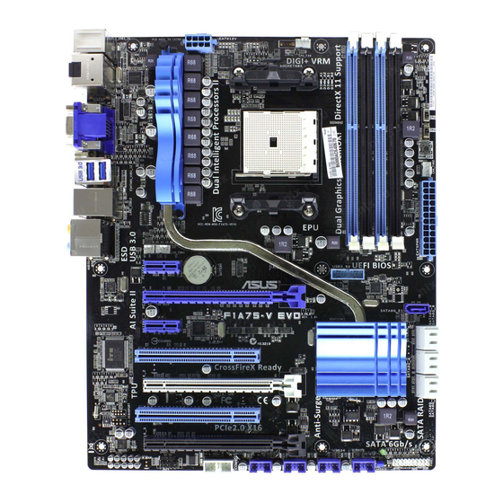
SPDIFO 1042 _HDMI MemOK! ESATA6G _USB3_12 LAN1_USB12 AUDIO PWR_FAN CHA_FAN1 EATXPWR USB3_56 Lithium Cell PCIEX1_1 CMOS Power 8111E PCIEX16_1 SATA6G_E1 F1A75-V EVO PCIEX1_2 ® Super PCI1 A75 FCH PCIEX16_2 PCI2 32Mb BIOS PCIEX16_3 SB_PWR SPDIF_OUT COM1 PANEL USB78 USB910 USB34... -
Page 21: Accelerated Processing Unit (Apu)
Installing the APU To install a APU: Locate the FM1 socket on the motherboard. F1A75-V EVO F1A75-V EVO APU socket FM1 Socket lever Press the lever sideways to unlock the socket, then lift it up to a 90°-100° angle. Ensure that the socket lever is lifted up to a 90°-100° angle; otherwise, the APU will not fit in completely. - Page 22 Connect the CPU fan cable to the CPU_FAN connector on the motherboard. CPU_FAN F1A75-V EVO F1A75-V EVO CPU fan connector DO NOT forget to connect the CPU fan connector! Hardware monitoring errors can occur if you fail to plug this connector.
-
Page 23: Installing The Heatsink And Fan
Your boxed CPU heatsink and fan assembly should come with installation instructions for the CPU, heatsink, and the retention mechanism. If the instructions in this section do not match the CPU documentation, follow the latter. Attach one end of the retention bracket to the retention module base. ASUS F1A75-V EVO 1-11... -
Page 24: System Memory
The figure illustrates the location of the DDR3 DIMM sockets: Channel Sockets Channel A DIMM_A1 and DIMM_A2 F1A75-V EVO Channel B DIMM_B1 and DIMM_B2 F1A75-V EVO 240-pin DDR3 DIMM sockets 1-12 Chapter 1: Product introduction... -
Page 25: Memory Configurations
• The maximum 64GB memory capacity can be supported with 16GB or above DIMMs. ASUS will update the memory QVL once the DIMMs are available in the market. • The default memory operation frequency is dependent on its Serial Presence Detect (SPD), which is the standard way of accessing information from a memory module. -
Page 26: Installing A Dimm
1.7.3 Installing a DIMM Unplug the power supply before adding or removing DIMMs or other system components. Failure to do so can cause severe damage to both the motherboard and the components. Press the retaining clips outward to DIMM notch unlock a DIMM socket. -
Page 27: Expansion Slots
This motherboard has three PCI Express 2.0 x16 slots that support PCI Express 2.0 x16 graphic cards complying with the PCI Express specifications. PCI Express operating mode VGA configuration PCIe x16_1 PCIe x16_2 PCIe x16_3 Single VGA/PCIe card x16 (Recommended for single VGA card) Dual VGA/PCIe card ASUS F1A75-V EVO 1-15... -
Page 28: Jumpers
Normal Clear RTC (Default) F1A75-V EVO Clear RTC RAM To erase the RTC RAM: 1. Turn OFF the computer and unplug the power cord. 2. Move the jumper cap from pins 1-2 (default) to pins 2-3. Keep the cap on pins 2-3 for about 5~10 seconds, then move the cap back to pins 1-2. -
Page 29: Connectors
8-channel configurations, the function of this port becomes Front Speaker Out. Microphone port (pink). This port connects to a microphone. Side Speaker Out port (gray). This port connects to the side speakers in the 8-channel audio configuration. ASUS F1A75-V EVO 1-17... - Page 30 Refer to the audio configuration table below for the function of the audio ports in the 2, 4, 6, or 8-channel configuration. Audio 2, 4, 6, or 8-channel configuration Headset Port 4-channel 6-channel 8-channel 2-channel Light Blue Line In Line In Line In Line In Lime...
-
Page 31: Internal Connectors
• The CPU_FAN connector supports a CPU fan of maximum 2A (24 W) fan power. • Only the CPU_FAN and CHA_FAN1/2 connectors support the ASUS Fan Xpert feature. • If you install two VGA cards, we recommend that you plug the rear chassis fan cable to the motherboard connector labeled CHA_FAN1/2 for better thermal environment. -
Page 32: Atx Power Connectors
The system may become unstable or may not boot up if the power is inadequate. • If you are uncertain about the minimum power supply requirement for your system, refer to the Recommended Power Supply Wattage Calculator at http://support.asus. com/PowerSupplyCalculator/PSCalculator.aspx?SLanguage=en-us for details. 1-20... - Page 33 This connector is for a serial (COM) port. Connect the serial port module cable to this connector, then install the module to a slot opening at the back of the system chassis. COM1 PIN 1 F1A75-V EVO F1A75-V EVO Serial port (COM1) connector The COM module is purchased separately. ASUS F1A75-V EVO 1-21...
-
Page 34: System Panel Connector
IDE_LED PWRSW RESET * Requires an ATX power supply F1A75-V EVO System panel connector • System power LED (2-pin PLED) This 2-pin connector is for the system power LED. Connect the chassis power LED cable to this connector. The system power LED lights up when you turn on the system power, and blinks when the system is in sleep mode. -
Page 35: Front Panel Audio Connector
Legacy AC’97 pin definition compliant definition F1A75-V EVO Front panel audio connector • We recommend that you connect a high-definition front panel audio module to this connector to avail of the motherboard high-definition audio capability. • If you want to connect a high definition front panel audio module to this connector, set the Front Panel Type item in the BIOS to [HD]. -
Page 36: Usb Connectors
This connector is for the additional USB 3.0 ports. Connect the USB 3.0 bracket cable to this connector, then install the USB 3.0 bracket to the rear side of the chassis. If your chassis support customized front panel installation, with ASUS USB 3.0 header, you can have a front panel USB 3.0 solution. -
Page 37: Onboard Switch
If the installed DIMMs still fail to boot after the whole tuning process, the DRAM_LED lights continuously. Replace the DIMMs with ones recommended in the Memory QVL (Qualified Vendors Lists) in this user manual or on the ASUS website at www.asus.com. - Page 38 TPU switch This switch allows you to enable or disable the TPU function. F1A75-V EVO F1A75-V EVO TPU switch • The TPU LED (ELED730) near the TPU switch lights when the switch setting is turned to Enable. • If you clear the CMOS or load the BIOS setup defaults, the related overclocking items in the BIOS menu follow the current setting of the TPU switch.
-
Page 39: Onboard Leds
F1A75-V EVO Standby Power Powered Off F1A75-V EVO Onboard LED DRAM LED DRAM LED checks the DRAM in sequence during motherboard booting process. If an error is found , the LED next to the error device will continue lighting until the problem is solved. - Page 40 EPU LED The EPU LED lights when the EPU switch is turned to Enable. ELED740 F1A75-V EVO F1A75-V EVO EPU LED 1-28 Chapter 1: Product introduction...
-
Page 41: Software Support
The contents of the Support DVD are subject to change at any time without notice. Visit the ASUS website at www.asus.com for updates. To run the Support DVD Place the Support DVD into the optical drive. - Page 42 1-30 Chapter 1: Product introduction...
-
Page 43: Chapter 2 Bios Information
BIOS in the future. Copy the original motherboard BIOS using the ASUS Update utility. 2.1.1 ASUS Update utility The ASUS Update is a utility that allows you to manage, save, and update the motherboard BIOS in Windows environment. ®... -
Page 44: Asus Ez Flash 2
Follow the onscreen instructions to complete the updating process. 2.1.2 ASUS EZ Flash 2 The ASUS EZ Flash 2 feature allows you to update the BIOS without using an OS-based utility. Before you start using this utility, download the latest BIOS file from the ASUS website at www.asus.com. -
Page 45: Asus Crashfree Bios 3 Utility
2.1.3 ASUS CrashFree BIOS 3 utility The ASUS CrashFree BIOS 3 is an auto recovery tool that allows you to restore the BIOS file when it fails or gets corrupted during the updating process. You can restore a corrupted BIOS file using the motherboard support DVD or a USB flash drive that contains the updated BIOS file. -
Page 46: Asus Bios Updater
2.1.4 ASUS BIOS Updater The ASUS BIOS Updater allows you to update BIOS in DOS environment. This utility also allows you to copy the current BIOS file that you can use as a backup when the BIOS fails or gets corrupted during the updating process. - Page 47 The BIOS Updater backup screen appears indicating the BIOS backup process. When BIOS backup is done, press any key to return to the DOS prompt. ASUSTek BIOS Updater for DOS V1.07 Current ROM Update ROM BOARD: F1A75-V EVO BOARD: Unknown VER: 0401 VER:...
-
Page 48: Updating The Bios File
Select the Load Optimized Defaults item under the Exit menu. Refer to section 2.9 Exit menu for details. • Ensure to connect all SATA hard disk drives after updating the BIOS file if you have disconnected them. ASUS F1A75-V EVO... -
Page 49: Bios Setup Program
BIOS setup program Use the BIOS Setup program to update the BIOS or configure its parameters. The BIOS screens include navigation keys and brief online help to guide you in using the BIOS Setup program. Entering BIOS Setup at startup To enter BIOS Setup at startup: •... -
Page 50: Bios Menu Screen
Selects the boot device priority • The boot device options vary depending on the devices you installed to the system. • The Boot Menu(F8) button is available only when the boot device is installed to the system. ASUS F1A75-V EVO... -
Page 51: Advanced Mode
The Advanced Mode provides advanced options for experienced end-users to configure the BIOS settings. The figure below shows an example of the Advanced Mode. Refer to the following sections for the detailed configurations. To access the EZ Mode, click Exit, then select ASUS EZ Mode. Back button Menu items... -
Page 52: Menu Items
You cannot select an item that is not user-configurable. A configurable field is highlighted when selected. To change the value of a field, select it and press <Enter> or click on it to display a list of options. 2-10 ASUS F1A75-V EVO... -
Page 53: Main Menu
Main menu The Main menu screen appears when you enter the Advanced Mode of the BIOS Setup program. The Main menu provides you an overview of the basic system information, and allows you to set the system date, time, language, and security settings. EFI BIOS Utility - Advanced Mode Exit Main... -
Page 54: Administrator Password
To clear the user password, follow the same steps as in changing a user password, but press <Enter> when prompted to create/confirm the password. After you clear the password, the User Password item on top of the screen shows Not Installed. 2-12 ASUS F1A75-V EVO... -
Page 55: Ai Tweaker Menu
Ai Tweaker menu The Ai Tweaker menu items allow you to configure overclocking-related items. Be cautious when changing the settings of the Ai Tweaker menu items. Incorrect field values can cause the system to malfunction. The configuration options for this section vary depending on the CPU and DIMM model you installed on the motherboard. -
Page 56: Ai Overclock Tuner [Auto]
This item appears only when The EPU Power Saving Mode is set to [Enabled] and allows you to set power saving mode. Configuration options: [Auto] [Light Power Saving Mode] [Medium Power Saving Mode] [Max Power Saving Mode] 2-14 ASUS F1A75-V EVO... -
Page 57: Oc Tuner
2.4.5 OC Tuner OC Tuner automatically overclocks the frequency and voltage of CPU and DRAM for enhancing the system performance. Press <Enter> and select OK to start automatic overclocking. 2.4.6 DRAM Timing Control The sub-items in this menu allow you to set the DRAM timing control features. Use the <+> and <->... -
Page 58: Dram Voltage [Auto]
CPU Current Capability [100%] This item provides wider total power range for overclocking. A higher value brings a wider total power range and extends the overclocking frequency range simultaneously. Configuration options: [100%] [110%] [120%] [130%] [140%] 2-16 ASUS F1A75-V EVO... -
Page 59: Apu Spread Spectrum [Auto]
Reducing phase number under light system loading to increase VRM efficiency. [Standard] Proceeds phase control depending on the CPU loading. [Optimized] Loads the ASUS optimized phase tuning profile. [Extreme] Proceeds the full phase mode. [Manual Adjustment] Allows manual adjustment. -
Page 60: Advanced Menu
Disables the CPB (Core Performance Boost) mode or set it to [Auto] for automatic configuration. Configuration options: [Disabled] [Auto] AMD PowerNow function [Enabled] Enables or disables the AMD PowerNow function. Configuration options: [Enabled] [Disabled] SVM [Enabled] Enables or disables CPU virtualization. Configuration options: [Disabled] [Enabled] 2-18 ASUS F1A75-V EVO... -
Page 61: Sata Configuration
2.5.2 SATA Configuration While entering Setup, the BIOS automatically detects the presence of SATA devices. The SATA Port items show Not Present if no SATA device is installed to the corresponding SATA port. OnChip SATA Channel [Enabled] Enables or disables onboard channel SATA port. Configuration options: [Disabled] [Enabled] The following three items appear only when you set the OnChip SATA Channel to [Enabled]. -
Page 62: Nb Configuration
Sets the front panel audio connector (AAFP) mode to high definition audio. [AC97] Sets the front panel audio connector (AAFP) mode to legacy AC’97. SPDIF Out Type [SPDIF] [SPDIF] Sets to [SPDIF] for SPDIF audio output. [HDMI] Sets to [HDMI] for HDMI audio output. 2-20 ASUS F1A75-V EVO... -
Page 63: Apm
ASM1061 Storage Controller [AHCI Mode] [Disabled] Disables the ASM1061 Storage controller. [IDE Mode] Enables the IDE Mode. [AHCI Mode] Enables the AHCI Mode. ASM1061 Storage OPROM [Enabled] [Enabled] Enables the ASM1061 Storage OPROM. [Disabled] Disables the ASM1061 Storage OPROM. Realtek LAN Controller [Enabled] [Enabled] Enables the Realtek LAN controller. -
Page 64: Monitor Menu
5V Voltage +5.160 V F1: General Help F2: Previous Values 12V Voltage +12.000 V F5: Optimized Defaults F10: Save ESC: Exit F12: Print Screen Anti Surge Support Enabled Version 2.00.1201. Copyright (C) 2011 American Megatrends, Inc. 2-22 ASUS F1A75-V EVO... -
Page 65: Cpu Temperature / Mb Temperature [Xxxºc/Xxxºf]
2.6.1 CPU Temperature / MB Temperature [xxxºC/xxxºF] The onboard hardware monitor automatically detects and displays the CPU and motherboard temperatures. Select Ignore if you do not wish to display the detected temperatures. 2.6.2 CPU / Chassis / Power Fan Speed [xxxx RPM] or [Ignore] / [N/A] The onboard hardware monitor automatically detects and displays the CPU / chassis / Power fan speeds in rotations per minute (RPM). -
Page 66: Chassis Q-Fan Control [Disabled]
The onboard hardware monitor automatically detects the voltage output through the onboard voltage regulators. Select Ignore if you do not want to detect this item. 2.6.6 Anti Surge Support [Enabled] This item allows you to enable or disable the Anti Surge function. Configuration options: [Disabled] [Enabled] 2-24 ASUS F1A75-V EVO... -
Page 67: Boot Menu
[Disabled] Disables the full screen logo display feature. Set this item to [Enabled] to use the ASUS MyLogo 2™ feature. Post Report [5 sec] This item appears only when the Full Screen Logo item is set to [Disabled] and allows you to set the waiting time for the system to display the post report. -
Page 68: Option Rom Messages [Force Bios]
• To select the boot device during system startup, press <F8> when ASUS Logo appears. • To access Windows OS in Safe Mode, press <F8> after POST. -
Page 69: Tools Menu
> ASUS SPD Information 2.8.1 ASUS EZ Flash 2 Utility Allows you to run ASUS EZ Flash 2. Press [Enter] to launch the ASUS EZ Flash 2 screen. For more details, see section 2.1.2 ASUS EZ Flash 2. 2.8.2 ASUS O.C. Profile This item allows you to store or load multiple BIOS settings. -
Page 70: Exit Menu
This option allows you to enter the EZ Mode screen. Launch EFI Shell from filesystem device This option allows you to attempt to launch the UEFI Shell application (shellx64.efi) from one of the available devices that have a filesystem. 2-28 ASUS F1A75-V EVO... -
Page 71: Asus Contact Information
+1-510-739-3777 +1-510-608-4555 Web site usa.asus.com Technical Support Telephone +1-812-282-2787 Support fax +1-812-284-0883 Online support support.asus.com ASUS COMPUTER GmbH (Germany and Austria) Address Harkort Str. 21-23, D-40880 Ratingen, Germany +49-2102-959911 Web site www.asus.de Online contact www.asus.de/sales Technical Support Telephone (Component) +49-1805-010923*...