Table of Contents
Advertisement
Quick Links
Advertisement
Table of Contents

Related Manuals for Asus F1A75


Summary of Contents for Asus F1A75
- Page 1 F1A75...
- Page 2 Product warranty or service will not be extended if: (1) the product is repaired, modified or altered, unless such repair, modification of alteration is authorized in writing by ASUS; or (2) the serial number of the product is defaced or missing.
-
Page 3: Table Of Contents
Contents Notices ......................vi Safety information ..................vii About this guide ..................viii F1A75 specifications summary ..............ix Chapter 1: Product introduction Welcome! ..................1-1 Package contents ................. 1-1 Special features ................1-1 1.3.1 Product highlights ............1-1 1.3.2 ASUS Exclusive Features ..........1-2 Before you proceed .............. - Page 4 Managing and updating your BIOS ..........2-1 2.1.1 ASUS Update utility ............2-1 2.1.2 ASUS EZ Flash 2 ............2-2 2.1.3 ASUS CrashFree BIOS 3 utility ........2-3 2.1.4 ASUS BIOS Updater ............2-4 BIOS setup program ..............2-7 Main menu .................. 2-11 2.3.1 System Language [English] ...........2-11...
- Page 5 Setup Mode [EZ Mode] ..........2-25 2.7.6 Boot Option Priorities ............ 2-25 2.7.7 Boot Override ..............2-25 Tools menu ................. 2-26 2.8.1 ASUS EZ Flash 2 Utility ..........2-26 2.8.2 ASUS O.C. Profile ............2-26 2.8.3 ASUS SPD Information ..........2-26 Exit menu ..................2-27...
-
Page 6: Notices
This class B digital apparatus complies with Canadian ICES-003. ASUS Recycling/Takeback Services ASUS recycling and takeback programs come from our commitment to the highest standards for protecting our environment. We believe in providing solutions for you to be able to responsibly recycle our products, batteries, other components as well as the packaging materials. -
Page 7: Safety Information
Complying with the REACH (Registration, Evaluation, Authorisation, and Restriction of Chemicals) regulatory framework, we published the chemical substances in our products at ASUS REACH website at http://csr.asus.com/english/REACH.htm. DO NOT throw the motherboard in municipal waste. This product has been designed to enable proper reuse of parts and recycling. -
Page 8: About This Guide
Refer to the following sources for additional information and for product and software updates. ASUS websites The ASUS website provides updated information on ASUS hardware and software products. Refer to the ASUS contact information. Optional documentation Your product package may include optional documentation, such as warranty flyers, that may have been added by your dealer. -
Page 9: F1A75 Specifications Summary
1066 MHz, non-ECC, unbuffered memory modules * The maximum 64GB memory capacity can be supported with 16GB or above DIMMs. ASUS will update the memory QVL once the DIMMs are available in the market. ** Refer to www.asus.com for the latest Memory QVL (Qualified Vendors List). - Page 10 - ASUS AI Charger - ASUS MemOK! - ASUS AI Suite II - ASUS Anti-Surge Protection - ASUS UEFI BIOS EZ Mode featuring graphics user interface ASUS Quiet Thermal Solution - ASUS Fanless Design: Stylish heatsink solution - ASUS Fan Xpert ASUS EZ DIY - ASUS O.C.
- Page 11 F1A75 specifications summary Back Panel I/O ports 1 x PS/2 mouse port (green) 1 x PS/2 keyboard port (purple) 1 x Optical S/PDIF output port 1 x LAN (RJ-45) port 6 x USB 2.0/1.1 ports 2 x USB 3.0 ports (blue)
-
Page 13: Chapter 1: Product Introduction
® The motherboard delivers a host of new features and latest technologies, making it another standout in the long line of ASUS quality motherboards! Before you start installing the motherboard, and hardware devices on it, check the items in your package with the list below. -
Page 14: Asus Exclusive Features
ASUS Exclusive Features ASUS TurboV Feel the adrenaline rush of real-time OC-now a reality with the ASUS TurboV. This easy OC tool allows you to overclock without exiting or rebooting the OS; and its user-friendly interface makes overclock with just a few clicks away. -
Page 15: Asus Mylogo 2
ASUS stylish heatsink will give users an extremely silent and cooling experience with the elegant appearance! ASUS EZ Flash 2 ASUS EZ Flash 2 is a user-friendly utility that allows you to update the BIOS without using a bootable floppy disk or an OS-based utility. Fan Xpert... -
Page 16: Before You Proceed
ASUS CrashFree BIOS 3 ASUS CrashFree BIOS 3 is an auto-recovery tool that allows you to restore a corrupted BIOS file using the bundled support DVD or a USB flash disk that contains the BIOS file. C.P.R. (CPU Parameter Recall) The BIOS C.P.R. -
Page 17: Motherboard Overview
Screw holes Place six screws into the holes indicated by circles to secure the motherboard to the chassis. DO NOT overtighten the screws! Doing so can damage the motherboard. Place this side towards the rear of the chassis. F1A75 ASUS F1A75... -
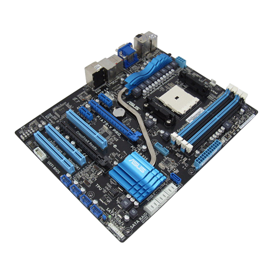
Page 18: Motherboard Layout
CPU_FAN USB56 ATX12V SPDIF_O2 USB34 MemOK! USB3_12 DRAM_LED LAN1_USB12 CHA_FAN1 AUDIO PWR_FAN USB3_34 PCIEX1_1 Lithium Cell CMOS Power 8111E PCIEX16_1 F1A75 PCIEX1_2 PCI1 Super ® A75 FCH PCIEX16_2 PCI2 32Mb BIOS PCI3 SB_PWR COM1 USB78 USB910 CHA_FAN2 PANEL CLRTC AAFP SPDIF_OUT 1.5.4... -
Page 19: Accelerated Processing Unit (Apu)
Installing the APU To install a APU: Locate the FM1 socket on the motherboard. F1A75 F1A75 processor socket FM1 Socket lever Press the lever sideways to unlock the socket, then lift it up to a 90°-100° angle. Ensure that the socket lever is lifted up to a 90°-100° angle; otherwise, the APU will not fit in completely. - Page 20 Connect the CPU fan cable to the CPU_FAN connector on the motherboard. CPU_FAN F1A75 F1A75 CPU fan connector DO NOT forget to connect the CPU fan connector! Hardware monitoring errors can occur if you fail to plug this connector. Chapter 1: Product introduction...
-
Page 21: Installing The Heatsink And Fan
Your boxed CPU heatsink and fan assembly should come with installation instructions for the CPU, heatsink, and the retention mechanism. If the instructions in this section do not match the CPU documentation, follow the latter. Attach one end of the retention bracket to the retention module base. ASUS F1A75... -
Page 22: System Memory
The figure illustrates the location of the DDR3 DIMM sockets: Channel Sockets Channel A DIMM_A1 and DIMM_A2 F1A75 Channel B DIMM_B1 and DIMM_B2 F1A75 240-pin DDR3 DIMM sockets 1-10 Chapter 1: Product introduction... -
Page 23: Memory Configurations
• The maximum 64GB memory capacity can be supported with 16GB or above DIMMs. ASUS will update the memory QVL once the DIMMs are available in the market. • The default memory operation frequency is dependent on its Serial Presence Detect (SPD), which is the standard way of accessing information from a memory module. - Page 24 F1A75 Motherboard Qualified Vendors Lists (QVL) DDR3-1866MHz capability DIMM socket support (Optional) Chip Vendors Part No. Size Brand Chip NO. Timing Voltage CORSAIR CMT4GX3M2A1866C9(XMP) 4GB(2 x 2GB) DS - 9-9-9-24 1.65V • • • CORSAIR CMZ8GX3M2A1866C9(XMP) 8GB(2 x 4GB) DS - 9-10-9-27 1.50V...
- Page 25 4GB(2 x 2GB) DS - 7-7-7-20 1.75V • • OCZ3P1333LV6GK 6GB(3 x 2GB) DS - 7-7-7-20 1.65V • • • AL7F8G73F-DJ2 SS PSC A3P1GF3FGF • • • AL8F8G73F-DJ2 DS PSC A3P1GF3FGF • • • (continued on the next page) ASUS F1A75 1-13...
- Page 26 • C*: Supports two pairs of modules inserted into both the blue slots and the black slots as two pairs of dual-channel memory configuration. Visit the ASUS website at www.asus.com for the latest QVL. 1-14 Chapter 1: Product introduction...
-
Page 27: Installing A Dimm
DIMM. Support the DIMM lightly with your fingers when pressing the retaining clips. The DIMM might get damaged when it flips out with extra force. DIMM notch Remove the DIMM from the socket. ASUS F1A75 1-15... -
Page 28: Expansion Slots
Expansion slots In the future, you may need to install expansion cards. The following sub-sections describe the slots and the expansion cards that they support. Unplug the power cord before adding or removing expansion cards. Failure to do so may cause you physical injury and damage motherboard components. -
Page 29: Jumpers
Normal Clear RTC (Default) F1A75 Clear RTC RAM To erase the RTC RAM: 1. Turn OFF the computer and unplug the power cord. 2. Move the jumper cap from pins 1-2 (default) to pins 2-3. Keep the cap on pins 2-3 for about 5~10 seconds, then move the cap back to pins 1-2. -
Page 30: Connectors
• If the steps above do not help, remove the onboard battery and move the jumper again to clear the CMOS RTC RAM data. After clearing the CMOS, reinstall the battery. • You do not need to clear the RTC when the system hangs due to overclocking. For system failure due to overclocking, use the CPU Parameter Recall (C.P.R) feature. - Page 31 Optical S/PDIF Out port. This port connects an external audio output device via an optical S/PDIF cable. USB 2.0 ports 5 and 6. These two 4-pin Universal Serial Bus (USB) ports are for USB 2.0/1.1 devices. PS/2 Keyboard port (purple). This port is for a PS/2 keyboard. ASUS F1A75 1-19...
-
Page 32: Internal Connectors
• The CPU_FAN connector supports a CPU fan of maximum 2A (24 W) fan power. • Only the CPU_FAN and CHA_FAN1/2 connectors support the ASUS Fan Xpert feature. • If you install two VGA cards, we recommend that you plug the rear chassis fan cable to the motherboard connector labeled CHA_FAN1/2 for better thermal environment. -
Page 33: Atx Power Connectors
The system may become unstable or may not boot up if the power is inadequate. • If you are uncertain about the minimum power supply requirement for your system, refer to the Recommended Power Supply Wattage Calculator at http://support.asus. com/PowerSupplyCalculator/PSCalculator.aspx?SLanguage=en-us for details. ASUS F1A75... - Page 34 This connector is for a serial (COM) port. Connect the serial port module cable to this connector, then install the module to a slot opening at the back of the system chassis. COM1 PIN 1 F1A75 F1A75 Serial port (COM1) connector The COM module is purchased separately. 1-22 Chapter 1: Product introduction...
-
Page 35: System Panel Connector
IDE_LED PWRSW RESET * Requires an ATX power supply F1A75 System panel connector • System power LED (2-pin PLED) This 2-pin connector is for the system power LED. Connect the chassis power LED cable to this connector. The system power LED lights up when you turn on the system power, and blinks when the system is in sleep mode. -
Page 36: Digital Audio Connector
Legacy AC’97 pin definition compliant definition F1A75 Front panel audio connector • We recommend that you connect a high-definition front panel audio module to this connector to avail of the motherboard high-definition audio capability. • If you want to connect a high definition front panel audio module to this connector, set the Front Panel Type item in the BIOS to [HD]. - Page 37 This connector is for the additional USB 3.0 ports. Connect the USB 3.0 bracket cable to this connector, then install the USB 3.0 bracket to the rear side of the chassis. If your chassis support customized front panel installation, with ASUS USB 3.0 header, you can have a front panel USB 3.0 solution.
-
Page 38: Onboard Switch
If the installed DIMMs still fail to boot after the whole tuning process, the DRAM_LED lights continuously. Replace the DIMMs with ones recommended in the Memory QVL (Qualified Vendors Lists) in this user manual or on the ASUS website at www.asus.com. -
Page 39: Onboard Leds
F1A75 Standby Power Powered Off F1A75 Onboard LED DRAM LED DRAM LED checks the DRAM in sequence during motherboard booting process. If an error is found , the LED next to the error device will continue lighting until the problem is solved. -
Page 40: Software Support
The contents of the Support DVD are subject to change at any time without notice. Visit the ASUS website at www.asus.com for updates. To run the Support DVD Place the Support DVD into the optical drive. -
Page 41: Chapter 2: Bios Information
BIOS in the future. Copy the original motherboard BIOS using the ASUS Update utility. 2.1.1 ASUS Update utility The ASUS Update is a utility that allows you to manage, save, and update the motherboard BIOS in Windows environment. ®... -
Page 42: Asus Ez Flash 2
Follow the onscreen instructions to complete the updating process. 2.1.2 ASUS EZ Flash 2 The ASUS EZ Flash 2 feature allows you to update the BIOS without using an OS-based utility. Before you start using this utility, download the latest BIOS file from the ASUS website at www.asus.com. -
Page 43: Asus Crashfree Bios 3 Utility
2.1.3 ASUS CrashFree BIOS 3 utility The ASUS CrashFree BIOS 3 is an auto recovery tool that allows you to restore the BIOS file when it fails or gets corrupted during the updating process. You can restore a corrupted BIOS file using the motherboard support DVD or a USB flash drive that contains the updated BIOS file. -
Page 44: Asus Bios Updater
2.1.4 ASUS BIOS Updater The ASUS BIOS Updater allows you to update BIOS in DOS environment. This utility also allows you to copy the current BIOS file that you can use as a backup when the BIOS fails or gets corrupted during the updating process. - Page 45 The BIOS Updater backup screen appears indicating the BIOS backup process. When BIOS backup is done, press any key to return to the DOS prompt. ASUSTek BIOS Updater for DOS V1.07 Current ROM Update ROM BOARD: F1A75 BOARD: Unknown VER: 0205 VER:...
-
Page 46: Updating The Bios File
• Ensure to load the BIOS default settings to ensure system compatibility and stability. Select the Load Optimized Defaults item under the Exit menu. Refer to section 2.9 Exit menu for details. • Ensure to connect all SATA hard disk drives after updating the BIOS file if you have disconnected them. ASUS F1A75... -
Page 47: Bios Setup Program
BIOS setup program Use the BIOS Setup program to update the BIOS or configure its parameters. The BIOS screens include navigation keys and brief online help to guide you in using the BIOS Setup program. Entering BIOS Setup at startup To enter BIOS Setup at startup: •... -
Page 48: Bios Menu Screen
Selects the boot device priority • The boot device options vary depending on the devices you installed to the system. • The Boot Menu(F8) button is available only when the boot device is installed to the system. ASUS F1A75... -
Page 49: Advanced Mode
The Advanced Mode provides advanced options for experienced end-users to configure the BIOS settings. The figure below shows an example of the Advanced Mode. Refer to the following sections for the detailed configurations. To access the EZ Mode, click Exit, then select ASUS EZ Mode. Back button Menu items... -
Page 50: Menu Items
You cannot select an item that is not user-configurable. A configurable field is highlighted when selected. To change the value of a field, select it and press <Enter> or click on it to display a list of options. 2-10 ASUS F1A75... -
Page 51: Main Menu
Main menu The Main menu screen appears when you enter the Advanced Mode of the BIOS Setup program. The Main menu provides you an overview of the basic system information, and allows you to set the system date, time, language, and security settings. EFI BIOS Utility - Advanced Mode Exit Main... -
Page 52: Administrator Password
To clear the user password, follow the same steps as in changing a user password, but press <Enter> when prompted to create/confirm the password. After you clear the password, the User Password item on top of the screen shows Not Installed. 2-12 ASUS F1A75... -
Page 53: Ai Tweaker Menu
Ai Tweaker menu The Ai Tweaker menu items allow you to configure overclocking-related items. Be cautious when changing the settings of the Ai Tweaker menu items. Incorrect field values can cause the system to malfunction. The configuration options for this section vary depending on the CPU and DIMM model you installed on the motherboard. -
Page 54: Ai Overclock Tuner [Auto]
This item appears only when The EPU Power Saving Mode is set to [Enabled] and allows you to set power saving mode. Configuration options: [Auto] [Light Power Saving Mode] [Medium Power Saving Mode] [Max Power Saving Mode] 2-14 ASUS F1A75... -
Page 55: Oc Tuner
2.4.5 OC Tuner OC Tuner automatically overclocks the frequency and voltage of CPU and DRAM for enhancing the system performance. Press <Enter> and select OK to start automatic overclocking. 2.4.6 DRAM Timing Control The sub-items in this menu allow you to set the DRAM timing control features. Use the <+> and <->... -
Page 56: Vsb Voltage [Auto]
This item allows you to set this function for better system performance. Configuration options: [Auto] [Disabled] [Enabled] The actual performance boost may vary depending on your CPU specification. 2.4.14 APU Spread Spectrum [Auto] [Auto] Automatic configuration. [Disabled] Enhances the PCIE overclocking ability. [Enabled] Sets to [Enabled] for EMI control. 2-16 ASUS F1A75... -
Page 57: Advanced Menu
Advanced menu The Advanced menu items allow you to change the settings for the CPU and other system devices. Be cautious when changing the settings of the Advanced menu items. Incorrect field values can cause the system to malfunction. EFI BIOS Utility - Advanced Mode Exit Main Ai Tweaker... -
Page 58: Sata Configuration
The USB devices can be used only for the BIOS setup program. [Auto] Allows the system to detect the presence of USB devices at startup. If detected, the USB controller legacy mode is enabled. If no USB device is detected, the legacy USB support is disabled. 2-18 ASUS F1A75... -
Page 59: Nb Configuration
Legacy USB3.0 Support [Enabled] [Enabled] Enables the support for USB 3.0 devices on legacy operating systems (OS). [Disabled] Disables the function. EHCI Hand-off [Disabled] [Enabled] Enables the support for operating systems without an EHCI hand-off feature. [Disabled] Disables the function. 2.5.4 NB Configuration Primary Video Device [PCIE / PCI Video]... -
Page 60: Apm
Enables Ring to generate a wake event. Power On By RTC [Disabled] [Disabled] Disables RTC to generate a wake event. When set to [Enabled], the items RTC Alarm Date (Days) and Hour/ [Enabled] Minute/Second will become user-configurable with set values. 2-20 ASUS F1A75... -
Page 61: Monitor Menu
Monitor menu The Monitor menu displays the system temperature/power status, and allows you to change the fan settings. EFI BIOS Utility - Advanced Mode Exit Ai Tweaker Main Advanced Monitor Boot Tool CPU Temperature CPU Temperature +45ºC / +113ºF MB Temperature +34ºC / +93ºF CPU Fan Speed 4515 RPM... -
Page 62: Chassis Q-Fan Control [Disabled]
[Silent] Sets to [Silent] to minimize the fan speed for quiet chassis fan operation. [Turbo] Sets to [Turbo] to achieve maximum chassis fan speed. [Manual] Sets to [Manual] to assign detailed fan speed control parameters. 2-22 ASUS F1A75... -
Page 63: Cpu Voltage, 3.3V Voltage, 5V Voltage, 12V Voltage
The following four items appear only when you set Chassis Fan Profile to [Manual]. Chassis Upper Temperature [70ºC] Use the <+> and <-> keys to adjust the upper limit of the CPU temperature. The values range from 20ºC to 90ºC. Chassis Fan Max. -
Page 64: Boot Menu
[Disabled] Disables the full screen logo display feature. Set this item to [Enabled] to use the ASUS MyLogo 2™ feature. Post Report [5 sec] This item appears only when the Full Screen Logo item is set to [Disabled] and allows you to set the waiting time for the system to display the post report. -
Page 65: Option Rom Messages [Force Bios]
• To select the boot device during system startup, press <F8> when ASUS Logo appears. • To access Windows OS in Safe Mode, press <F8> after POST. -
Page 66: Tools Menu
> ASUS SPD Information 2.8.1 ASUS EZ Flash 2 Utility Allows you to run ASUS EZ Flash 2. Press [Enter] to launch the ASUS EZ Flash 2 screen. For more details, see section 2.1.2 ASUS EZ Flash 2. 2.8.2 ASUS O.C. Profile This item allows you to store or load multiple BIOS settings. -
Page 67: Exit Menu
Load Optimized Defaults Save Changes & Reset Discard Changes & Exit ASUS EZ Mode Launch EFI Shell from filesystem device Load Optimized Defaults This option allows you to load the default values for each of the parameters on the Setup menus. - Page 68 2-28 ASUS F1A75...
-
Page 69: Asus Contact Information
+1-510-739-3777 +1-510-608-4555 Web site usa.asus.com Technical Support Telephone +1-812-282-2787 Support fax +1-812-284-0883 Online support support.asus.com ASUS COMPUTER GmbH (Germany and Austria) Address Harkort Str. 21-23, D-40880 Ratingen, Germany +49-2102-959911 Web site www.asus.de Online contact www.asus.de/sales Technical Support Telephone (Component) +49-1805-010923*...