Biostar M7VIG PRO User Manual
M7vig pro user's manual
Hide thumbs
Also See for M7VIG PRO:
- Bios setup manual (30 pages) ,
- Test report (58 pages) ,
- User manual (50 pages)
Table of Contents
Advertisement
Available languages
Available languages
M
7
V
I
G
P
r
o
M
7
V
I
G
P
r
o
M
7
V
I
G
P
r
o
FCC Statement and Copyright
This equipment has been tested and found to comply with the limits of a
Class B digital device, pursuant to Part 15 of the FCC Rules. These limits
are designed to provide reasonable protection against harmful interference
in a residential installation. This equipment generates, uses and can
radiate radio frequency energy and, if not installed and used in
accordance with the instructions, may cause harmful interference to radio
communications. There is no guarantee that interference will not occur in a
particular installation.
The vendor makes no representations or warranties with respect to the
contents here of and specially disclaims any implied warranties of
merchantability or fitness for any purpose. Further the vendor reserves the
right to revise this publication and to make changes to the contents here of
without obligation to notify any party beforehand.
Duplication of this publication, in part or in whole is not allowed without
first obtaining the vendor's approval in writing.
The content of this user's is subject to be changed without notice and we
will not be responsible for any mistakes found in this user's manual. All the
brand and product names are trademarks of their respective companies.
i
Advertisement
Table of Contents

Related Manuals for Biostar M7VIG PRO


Summary of Contents for Biostar M7VIG PRO
- Page 1 FCC Statement and Copyright This equipment has been tested and found to comply with the limits of a Class B digital device, pursuant to Part 15 of the FCC Rules. These limits are designed to provide reasonable protection against harmful interference in a residential installation.
-
Page 2: Table Of Contents
DDR DIMM Modules: DDR1-2 ................... 4 SDR DIMM Modules: SDR1-2.................... 4 Jumpers, Headers, Connectors & Slots ................6 ESPAÑOL ....................11 Características del M7VIG Pro ..................11 Contenido del Paquete....................12 Disposición del M7VIG Pro..................... 12 Instalación de la CPU ...................... 13 Módulos DDR DIMM: DDR1-2 .................. -
Page 3: English
English M7VIG Pro Features Use VIA VT8375 (KM266)/ VT8235 Chipset, Winbond W83697HF, LAN Chip- VT6103 (optional). Contains on board I/O facilities, which include one serial port, one VGA port, a parallel port, a PS/2 mouse port, a PS/2 keyboard port, audio ports, USB 2.0 ports, a LAN port (optional) and a game port. -
Page 4: Package Contents
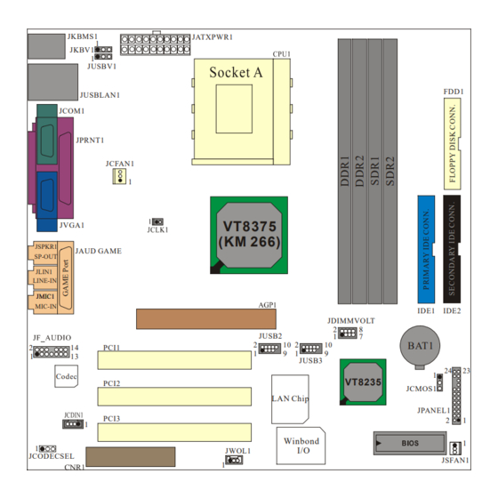
HDD Cable X 1, FDD Cable X 1, Fully Setup Driver CD X 1 Flash Memory Writer for BIOS update X 1 USB Cable X 2 (Optional) Rear I/O Panel for ATX Case X 1 (Optional) Layout of M7VIG Pro JKBMS1 JATXPWR1 JKBV1... -
Page 5: Cpu Installation
CPU Installation Pull the lever sideways away from the socket then raise the lever up to 90-degree angle. Locate Pin A in the socket and lock for the white dot or cut edge in the CPU. Match Pin A with the white dot/cut edge then insert the CPU. -
Page 6: Ddr Dimm Modules: Ddr1-2
DDR DIMM Modules: DDR1-2 DRAM Access Time: 2.5V Unbuffered DDR 200/266 MHz Type required. DRAM Type: 64MB/ 128MB/ 256MB/ 512MB/ 1GB DIMM Module (184 pin) DIMM Socket DDR Module Total Memory Location Size (MB) DDR 1 64MB/128MB/256MB/512MB/1GB Max is DDR 2 64MB/128MB/256MB/512MB/1GB The list shown above for DRAM configuration is only for reference. - Page 7 How to install a DIMM Module DDR SDRAM 1. The DIMM socket has a “ Plastic Safety Tab”, and the DIMM memory module has an “Asymmetrical notch”, DIMM memory module can only fit into the slot in one direction. 2. Push the tabs out. Insert the DIMM memory modules into the socket at a 90-degree angle, then push down vertically so that it will...
-
Page 8: Jumpers, Headers, Connectors & Slots
Jumpers, Headers, Connectors & Slots Hard Disk Connectors: IDE1/ IDE2 The motherboard has a 32-bit Enhanced PCI IDE Controller that provides PIO Mode 0~4, Bus Master, and Ultra DMA / 33/ 66/ 100/ 133 functionality. It has two HDD connectors IDE1 (primary) and IDE2 (secondary). - Page 9 Power Connectors: JATXPWR1 JATXPWR1 JATXPWR1 (ATX Main Power Conn.) (ATX Main Power Conn.) DIMM Power Selection Connector: JDIMMVOLT Pin 1-2 on ==> 2.5V Pin 3-4 on ==> 2.6V JDIMMVOLT Pin 5-6 on ==> 2.7V Pin 7-8 on ==> 2.8V (Default ==> 2.5V) It strongly recommended to set DDR DIMM voltage in default setting 2.5V, and it for over voltage function.
- Page 10 Front USB Header: JUSB2/ JUSB3 Pin1,2 ==> +5V Pin3,4 ==> Data(-) Pin5,6 ==> Data(+) Pin7,8 ==> Ground Pin9 ==> KEY JUSB2/3 Pin10 ==> NA 5V/ 5VSB Selection for USB: JUSBV1 Pin 1-2 on ==> 5V Pin 2-3 on ==> 5V_SB JUSBV1 CPU Frequency Selection: JCLK1 On ==>...
- Page 11 CNR Codec Primary/ Secondary Selection: JCODECSEL Pin 1-2 ==> On board primary Codec (Default) Pin 2-3 ==> CNR primary Codec JCODECSEL Front Panel Connector: JPANEL1 ==> Speaker Conn. HLED ==> Hard Driver LED ==> Reset Button ON/OFF ==> Infrared Conn. HLED PWR_LED ==>...
- Page 12 JF_AUDIO Pin1 ==> Mic In Pin2 ==> Ground Pin3 ==> Mic Power Pin4 ==> Audio Power Pin5 ==> RT Line Out Pin6 ==> RT Line Out Pin7 ==> Reserved Pin8 ==> KEY Pin9 ==> LFT Line Out Pin10 ==> LFT Line Out Pin11==>...
-
Page 13: Español
Español Características del M7VIG Pro Usa Chipset VIA VT8375 (KM266)/ VT8235, Winbond W83697HF, LAN Chip- VT6103 (opcional). Contiene facilidades I/O integrados en la placa madre en el que incluye un puerto en serie, un puerto VGA, un puerto paralelo, un puerto de ratón PS/2, un puerto de teclado PS/2, puerto de audio, puertos USB 2.0, un... -
Page 14: Contenido Del Paquete
Cable HDD X 1, Cable FDD X 1, Configuración Completa del Driver CD X Flash Memory Writer para actualización del BIOS X 1 Cable USB X 2 (Opcional) Panel Trasero I/O para Caja ATX X 1 (Opcional) Disposición del M7VIG Pro JKBMS1 JATXPWR1 JKBV1... -
Page 15: Instalación De La Cpu
Instalación de la CPU Tire de la palanca del lado del zócalo, luego levante la palanca hasta un ángulo de 90 grados. Sitúe el contacto A del zócalo y busque el punto blanco o corte el borde en la CPU. Empareje el contacto A con el punto blanco/ corte del borde, luego inserte la CPU. -
Page 16: Módulos Ddr Dimm: Ddr1-2
Módulos DDR DIMM: DDR1-2 DRAM Tiempo de Acceso: 2.5V Unbuffered DDR 200/266 MHz Tipo requerido. DRAM Tipo: 64MB/ 128MB/ 256MB/ 512MB/ 1GB Módulo DIMM (184 pin) Localización Total del del Módulo Tamaño de Módulo DDR DIMM Memoria (MB) DDR 1 64MB/128MB/256MB/512MB/1GB Máximo de DDR 2... - Page 17 Para la configuración arriba mencionada, usted solamente puede utilizar un sólo tipo de memoria en ésta placa madre. Está prohibido insertar los dos tipos de memoria simultáneamente. Solamente puede insertar DDR o SDRAM. Cómo instalar un Módulo DIMM DDR SDRAM 1.
-
Page 18: Conectores, Cabezales, Puentes Y Ranuras
Conectores, Cabezales, Puentes y Ranuras Conectores del Disco Duro: IDE1/ IDE2 La placa madre tiene un controlador de 32-bit PCI IDE que proporciona Modo PIO 0~4, Bus Master, y funcionalidad Ultra DMA / 33/ 66/ 100. Tiene dos conectores HDD IDE1 (primario) y IDE2 (secundario). El conector IDE puede conectar a un master y un drive esclavo, así... - Page 19 Conectores de Corriente: JATXPWR1 JATXPWR1 JATXPWR1 (ATX Main Power Conn.) (ATX Conector de Corriente Principal.) Conector de Selección de la Corriente DIMM: JDIMMVOLT Contacto 1-2 on ==> 2.6V Contacto 3-4 on ==> 2.7V JDIMMVOLT Contacto 5-6 on ==> 2.8V Contacto 7-8 on ==> 2.9V (Predeterminado ==>...
- Page 20 Cabezal Frontal USB: JUSB2/ JUSB3 Contacto1,2 ==> +5V Contacto3,4 ==> Dato(-) Contacto5,6 ==> Dato(+) Contacto7,8 ==> Tierra JUSB2/3 Contacto9 ==> KEY Contacto10 ==> NA 5V/ 5VSB Selección para USB: JUSBV1 Contacto 1-2 on ==> 5V Contacto 2-3 on ==> 5V_SB JUSBV1 Selección de Frecuencia del CPU: JCLK1 On ==>...
- Page 21 CNR Codec de Selección Primario/ Secundario: JCODECSEL JCODECSEL Contacto 1-2 ==> Codec Primario On-board (Predeterminado) Contacto 2-3 ==> Codec Primario CNR Conector del Panel Frontal: JPANEL1 ==> Conector del Altavoz HLED ==> LED del Disco Duro ==> Boton de Reinicio ON/OFF ==>...
- Page 22 JAUDIO1 Pin1 ==> Entrada del Mic Pin2 ==> Tierra Pin3 ==> Corriente del Mic Pin4 ==> Corriente del Audio Pin5 ==> RT Salida de Linea Pin6 ==> RT Salida de Linea Pin7 ==> Reservado Pin8 ==> KEY Pin9 ==> LFT Salida de Linea Pin10 ==>...
-
Page 23: Trouble Shooting
Trouble Shooting PROBABLE SOLUTION No power to the system at all Power light don’t * Make sure power cable is securely plugged in illuminate, fan inside power supply does not turn * Replace cable on. Indicator light on keyboard does not turn on * Contact technical support PROBABLE SOLUTION... -
Page 24: Solución De Problemas
Solución de Problemas CAUSA PROBABLE SOLUCIÓN No hay corriente en el sistema. La luz de * Asegúrese que el cable de transmisión esté corriente no ilumina, ventilador dentro de la seguramente enchufado. fuente de alimentación apagada. Indicador de * Reemplace el cable. luz del teclado apagado. - Page 25 11/19/2002...