Table of Contents
Advertisement
M
7
V
I
G
4
0
0
M
7
V
I
G
4
0
0
M
7
V
I
G
4
0
0
FCC Information and Copyright
This equipment has been tested and found to comply with the limits of a
Class B digital device, pursuant to Part 15 of the FCC Rules. These limits
are
designed
to
provide
reasonable
protection
against
harmful
interference in a residential installation. This equipment generates, uses
and can radiate radio frequency energy and, if not installed and used in
accordance with the instructions, may cause harmful interference to radio
communications. There is no guarantee that interference will not occur in
a particular installation.
The vendor makes no representations or warranties with respect to the
contents here of and specially disclaims any implied
of
warranties
merchantability or fitness for any purpose. Further the vendor reserves
the right to revise this publication and to make changes to the contents
here of without obligation to notify any party beforehand.
Duplication of this publication, in part or in whole, is not allowed without
first obtaining the vendor's approval in writing.
The content of this user's manual is subject to be changed without notice
and we will not be responsible for any mistakes found in this user's
manual. All the brand and product names are trademarks of their
respective companies.
i
Advertisement
Table of Contents

Related Manuals for Biostar M7VIG400


Summary of Contents for Biostar M7VIG400
- Page 1 FCC Information and Copyright This equipment has been tested and found to comply with the limits of a Class B digital device, pursuant to Part 15 of the FCC Rules. These limits designed provide reasonable protection against harmful interference in a residential installation. This equipment generates, uses and can radiate radio frequency energy and, if not installed and used in accordance with the instructions, may cause harmful interference to radio communications.
-
Page 2: Table Of Contents
LAYOUT OF M7VIG 400... 1 COMPONENT INDEX... 2 M7VIG 400 SYSTEM STRUCTURE... 3 ENGLISH... 4 M7VIG 400 Features ...4 Package contents...5 How to set up Jumper...6 CPU Installation...6 DDR DIMM Modules: DDR1, DDR2...7 Installing DDR Module ...8 Jumpers, Headers, Connectors & Slots ...8 FRANÇAIS ... -
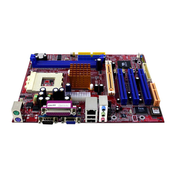
Page 3: Layout Of M7Vig 400
Layout of M7VIG 400 NOTE: ●represents the first pin. -
Page 4: Component Index
Components Index A. Back Panel Connectors B. CPU Fan Connector (JCFAN1) C. ATX Power Connector (JATXPWER1) D. North Bridge Fan Connector (JNFAN1)* N. System FAN Header (JSFAN1) E. CD-ROM Audio-In Header (JCDIN1) F. Front Audio Header (JF_AUDIO1) G. Accelerated Graphics Port Slot (AGP1) Q. Frequency Selection (JCLK1) H. -
Page 5: M7Vig 400 System Structure
M7VIG 400 System Structure... -
Page 6: English
English M7VIG 400 Features A. Hardware Provides Socket A. ® Supports single AMD Athlon XP/ Duron Family processor. Front Side Bus at 200/266/333 MHz. Chipset North Bridge: VIA KM266 Pro. South Bridge: VIA VT8235. Main Memory Supports up to 2 DDR devices. Supports 200/266/333 MHz (without ECC) DDR devices. -
Page 7: Package Contents
On Board Peripherals a. Rear side 1 serial port. 1 VGA port. 1 parallel port. (SPP/EPP/ECP mode) Audio ports in vertical position. 1 RJ-45 LAN jack. PS/2 mouse and PS/2 keyboard. 4 USB2.0 ports. b. Front Side 1 floppy port supports 2 FDDs with 360K, 720K, 1.2M, 1.44M and 2.88Mbytes. 2 USB2.0 ports. -
Page 8: How To Set Up Jumper
How to set up Jumper The illustration shows how to set up a jumper. When the Jumper cap is placed on pins, the jumper is “close”. If no jumper cap is placed on the pins, the jumper is ”open”. The illustration shows a 3-pin jumper whose pin 1 and 2 are “close”... -
Page 9: Ddr Dimm Modules: Ddr1, Ddr2
CPU Fan Header: JCFAN1 JCFAN1 System Fan Header: JSFAN1 JSFAN1 North Bridge Fan Header: JNFAN1 (optional) JNFAN1 DDR DIMM Modules: DDR1, DDR2 DRAM Access Time: 2.5V Unbuffered/ DDR 200 MHz (PC1600)/DDR 266 MHz (PC2100)/ DDR 333 MHz (PC2700) Type required. DRAM Type: 64MB/ 128MB/ 256MB/ 512MB/ 1GB DIMM Module (184 pin) DIMM Socket DDR Module... -
Page 10: Installing Ddr Module
The first hard drive should always be connected to IDE1. Peripheral Component Interconnect Slots: PCI 1-3 This motherboard is equipped with 3 standard PCI slots. PCI stands for Peripheral Component Interconnect, and it is a bus standard for expansion cards. This PCI slot is designated as 32 bits. -
Page 11: Front Panel Connector: Jpanel1
JCI1 Front Panel Connector: JPANEL1 PWR_LED (+ ) JPANEL1 Assignment Function Speaker Connector Speaker HDD LED (+) Hard Drive HDD LED (-) Ground Reset Button Reset Control IrDA Connector IRTX Power Connectors: JATXPWER1 Assignment Standby Voltage Ground ON/ OFF (+ ) (- ) (+ ) (- ) HLED... - Page 12 JATXPWER1 Clear CMOS Jumper: JCMOS1 JCMOS1 Pin 1-2 Close Pin 2-3 Close ※ Clear CMOS Procedures: 1. Remove AC power line. 2. Set the jumper to “Pin 2-3 Close”. 3. Wait for five seconds. 4. Set the jumper to “Pin 1-2 Close”. 5.
- Page 13 Front Panel Audio Header: JF_AUDIO1 Assignment Mic In/ Center Mic Power/ Bass Right Line Out/ Speaker Out Right Reserved Left Line Out/ Speaker Out Left Right Line In/ Rear Speaker Right Left Line In/ Rear Speaker Left Front USB Header: JUSB2 Assignment JUSB1/ JUSB2 Back Panel Connectors...
- Page 14 6 Channel Speakers Speaker Out/ Front Speaker (Right & Left) Line In/ Rear Speaker (Left & Right) Mic In/ Center & Bass...
-
Page 15: Français
Français Caractéristiques de M7VIG 400 A. Matériel Processeur Avec socket A. Prise en charge du processeur AMD Bus frontal à 200/266/333 MHz. Jeu de puces North Bridge : VIA KM266 Pro. South Bridge : VIA VT8235. Mémoire principale Prise en charge de deux périphériques 2 DDR. Prise en charge des périphériques DDR 200/266/333 MHz (sans ECC). -
Page 16: Contenu De L'emballage
Puce: CMI 9761A Conforme aux spécifications AC’97. Interface AC’97 2.3. Prise en charge de 6 canaux. Prise en charge de la microphone stereo. Périphériques intégrés a. Côté arrière 1 port série. 1 port VGA. 1 port parallèle (mode SPP/EPP/ECP) 1 port audio en position verticale. 1 RJ-45 LAN Jack. -
Page 17: Warpspeeder
WarpSpeeder™ Introduction [ WarpSpeeder™ ], a new powerful control utility, features three user-friendly functions including Overclock Manager, Overvoltage Manager, and Hardware Monitor. With the Overclock Manager, users can easily adjust the frequency they prefer or they can get the best CPU performance with just one click. The Overvoltage Manager, on the other hand, helps to power up CPU core voltage and Memory voltage. -
Page 18: Installation
Installation Execute the setup execution file, and then the following dialog will pop up. Please click “Next” button and follow the default procedure to install. When you see the following dialog in setup procedure, it means setup is completed. If the “Launch the WarpSpeeder Tray Utility” checkbox is checked, the Tray Icon utility and [WarpSpeeder™] utility will be automatically and immediately launched after you click “Finish”... -
Page 19: Usage
Usage The following figures are just only for reference, the screen printed in this user manual will change according to your motherboard on hand. [WarpSpeeder™] includes 1 tray icon and 5 panels: 1. Tray Icon: Whenever the Tray Icon utility is launched, it will display a little tray icon on the right side of... - Page 20 This utility is responsible for conveniently invoking [WarpSpeeder™] Utility. You can use the mouse by clicking the left button in order to invoke [WarpSpeeder™] directly from the little tray icon or you can right-click the little tray icon to pop up a popup menu as following figure.
- Page 21 3. Voltage Panel Click the Voltage button in Main Panel, the button will be highlighted and the Voltage Panel will slide out to up as the following figure. In this panel, you can decide to increase CPU core voltage and Memory voltage or not. The default setting is “No”.
- Page 22 4. Overclock Panel Click the Overclock button in Main Panel, the button will be highlighted and the Overclock Panel will slide out to left as the following figure.
- Page 23 Overclock Panel contains the these features: a. “–3MHz button”, “-1MHz button”, “+1MHz button”, and “+3MHz button”: provide user the ability to do real-time overclock adjustment. Warning: Manually overclock is potentially dangerous, especially when the overclocking percentage is over 110 %. We strongly recommend you verify every speed you overclock by click the Verify button.
- Page 24 “Auto-overclock button”: User can click this button and [ WarpSpeeder™ ] will set the best and stable performance and frequency automatically. [ WarpSpeeder™ ] utility will execute a series of testing until system fail. Then system will do fail-safe reboot by using Watchdog function. After reboot, the [ WarpSpeeder™ ] utility will restore to the hardware default setting or load the verified best and stable frequency according to the Recovery Dialog’s setting.
- Page 25 5. Hardware Monitor Panel Click the Hardware Monitor button in Main Panel, the button will be highlighted and the Hardware Monitor panel will slide out to left as the following figure. In this panel, you can get the real-time status information of your system. The information will be refreshed every 1 second.
- Page 26 Note: Because the overclock, overvoltage, and hardware monitor features are controlled by several separate chipset, [ WarpSpeeder™ ] divide these features to separate panels. If one chipset is not on board, the correlative button in Main panel will be disabled, but will not interfere other panels’ functions.
-
Page 27: Trouble Shooting
Trouble Shooting PROBABLE No power to the system at all Power light don’t illuminate, fan inside power supply does not turn on. Indicator light on keyboard does not turn on PROBABLE System inoperative. Keyboard lights are on, power indicator lights are lit, hard drive is spinning. - Page 28 3/26/2004...