Table of Contents
Advertisement
Quick Links
®
Intel
Core i7 Series Processor Motherboard
USER'S MANUAL
*
The WEEE marking on the product indicates this product must not be disposed of with user's
other household waste and must be handed over to a designated collection point for the
recycling of waste electrical and electronic equipment!!
*
The WEEE marking applies only in European Union's member states.
GA-6TXSL-RH
®
TM
Intel
Core
2 Quad processorMotherboard
Rev. 1001
Advertisement
Table of Contents

Related Manuals for Gigabyte GA-6TXSL


Summary of Contents for Gigabyte GA-6TXSL
- Page 1 GA-6TXSL-RH ® Intel Core i7 Series Processor Motherboard USER’S MANUAL ® Intel Core 2 Quad processorMotherboard Rev. 1001 The WEEE marking on the product indicates this product must not be disposed of with user's other household waste and must be handed over to a designated collection point for the recycling of waste electrical and electronic equipment!! The WEEE marking applies only in European Union's member states.
- Page 2 Gigabyte's prior written permission. Specifications and features are subject to change without prior notice. Product Manual Classification In order to assist in the use of this product, Gigabyte has categorized the user manual in the following: For detailed product information and specifications, please carefully read the "Product User Manual".
-
Page 3: Table Of Contents
Table of Contents Item Checklist .........................4 Chapter 1 Introduction ....................5 1-1 Features Summary ....................5 1.2 GA-6TXSL-RH Motherboard Components ............7 Chapter 2 Hardware Installation Process ...............9 2-1: Install Memory Modules ..................9 2-2: Connect ribbon cables, cabinet wires, and power supply ........ 11 2-3: Connectors Introduction &... -
Page 4: Item Checklist
Floppy cable I/O Shield Kit CD for motherboard driver & utility SATA Power cable x 6 GA-6TXSL-RH Quick Reference Guide USB+1394 cable x 1 WARNING! Computer motherboards and expansion cards contain very delicate Integrated Circuit (IC) chips. -
Page 5: Chapter 1 Introduction
Introduction Chapter 1 Introduction Features Summary Form Factor 12” x 9.6”(3.5cm X 24.4cm) ATX form factor, 6 layers PCB. Supports single Intel ® Core i7 processor Intel ® Dual Core/Quad Core in LGA 1366 socket L3 cache varies with CPU up to 12M ®... - Page 6 GA-6TXSL-RH Motherboard On-Board LAN Intel ® 82567LM GbE controller Supports WOL, PXE On-Board Peripherals 1 x Floppy connector 2 x PS/2 connectors 1 x Parallel port supports Normal/EPP/ECP mode 2 x Serial port (COM) ...
-
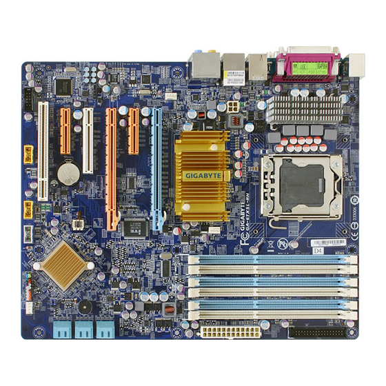
Page 7: Ga-6Txsl-Rh Motherboard Components
Introduction GA-6TXSL-RH Motherboard Components 1. CPU 24. SATA Cable1.4 2. Intel X58 ICH 25. SATA Cable2.5 3. Intel 82801IJR ICH10R 26. SATA Cable3.6 4. ITE IT 8720 27. 24pin ATX power connector 5. PCIE x 16 Slot 28. Floppy connector 6. - Page 8 GA-6TXSL-RH Motherboard...
-
Page 9: Chapter 2 Hardware Installation Process
Hardware Installation Process 2-1: Install Memory Modules GA-6TXSL-RH has 6 triple inline memory module (DIMM) sokcets. It supports Triple Channels Technology. The BIOS will automatically detects memory type and size during system boot. For detail DIMM installation, please refer to the following instructions. - Page 10 GA-6TXSL-RH Motherboard Table 1. Supported DIMM Module Type Dual Channel Memory Configurations Table DDR3_2 DDR3_1 DDR3_4 DDR3_3 DDR3_6 DDR3_5 Two M odules DS/SS DS/SS Four M odules DS/SS DS/SS DS/SS DS/SS 3 Channel Memory Configurations Table DDR3_2 DDR3_1 DDR3_4 DDR3_3 DDR3_6 DDR3_5...
-
Page 11: 2-2: Connect Ribbon Cables, Cabinet Wires, And Power Supply
Hardware Installation Process 2-2: Connect ribbon cables, cabinet wires, and power supply 2-2-1 : I/O Back Panel Introduction... -
Page 12: 2-3: Connectors Introduction & Jumper Setting
GA-6TXSL-RH Motherboard 2-3: Connectors Introduction & Jumper Setting 18 17 1. 24pin ATX power connector 2. 4pin 12V ATX power connector 3. Floppy connector 4. SATA Cable1.4 5. SATA Cable2.5 6. SATA Cable3.6 7. Front Auio Cable connector 8. Front USB connector 9. - Page 13 Connector Introduction 1) ATX1 (Auxuliary Power Connector) AC power cord should only be connected to your power supply unit after ATX power cable and other related devices are firmly connected to the mainboard. PIN No. Definition +3.3V +3.3V 5VSB +12V Secure Gigital / +12V Memory Stick...
- Page 14 GA-6TXSL-RH Motherboard 3 ) FDD (Floppy Connector) ATX_12V Please connect the floppy drive ribbon cables to FDD. It supports 720K,1.2M,1.44M and 2.88Mbytes floppy disk types. The red stripe of the ribbon cable must be the same side with the Pin1.
- Page 15 Memory Stick Connector Introduction 4/5/6) S_ATA 1~6 (Serial ATA cable connectors) You can connect the Serial ATA device to this connector, it provides you high speed transfer rates (3.0Gb/s). Serial ATA Pin No. Definition SPDIF AUX_IN CD_IN 7) FAUDIO_ACZ (Front AUDIO cable connector) CPU_FAN If you want to use Front Audio connector, you must remove 5-6, 9-10 Jumper.
- Page 16 GA-6TXSL-RH Motherboard 8 ) F_USB1 (Internal USB cable connector) Be careful with the polarity of the front USB connector. Check the pin assignment carefully while you connect the front USB cable, incorrect connection between the cable and connector will make the device unable to work or even damage it. For optional front USB cable, please contact your local dealer.
- Page 17 Connector Introduction 10 ) 1394 (IEEE 1394 cable connectors) Pin No. Definition TPA 1+ TPA 1- TPB 1+ TPB 1- BUS VCC BUS VCC No Pin 11 ) PWR_LED(System Power LED Header) This header can be used to connect a system power LED on the chasis to indicate system power status.
- Page 18 GA-6TXSL-RH Motherboard 12 ) F_Panel (2X10 Pins Front Panel connector) Please connect the power LED, PC speaker, reset switch and power switch of your chassis front panel to the F_PANEL connector according to the pin assignment above. NOTE!! Please note that the onborad front panel connector must attach with adapt cable to enable front panel function.
- Page 19 Connector Introduction 13 ) BAT1 (Battery) Power CAUTION Danger of explosion if battery is incorrectly replaced. Replace only with the same or equivalent F2_1394 type recommended by the manufacturer. Dispose of used batteries according to the manufacturer’s instructions. If you want to erase CMOS...
- Page 20 GA-6TXSL-RH Motherboard 15 ) REAR_FAN (Front Fan and Rear fan cable connectors) This connector allows you to link with the cooling fan on the system case to lower the system temperature. These connectors are for system use only. Pin No.
- Page 21 Connector Introduction 17 ) JP2 (Skip password jumper) 1-2 Close: Normal operation (Default setting) 2-3 Close: Skip Supervisor Password inBIOS setup menu 18 ) JP3 (BIOS recovery jumper) 1-2 Close: Normal operation (Default setting) 2-3 Close: Enable BIOS Recovery mode...
- Page 22 GA-6TXSL-RH Motherboard 19 ) JP1 (Clear CMOS jumper) You may clear the CMOS data to restore its default values by this jumper. Default value doesn’t include the “Shunter” to prevent from improper use this jumper. To clear CMOS, temporarily short 1-2 pin.
-
Page 23: 2-4: Block Diagram
Block Diagram 2-4: Block Diagram CLOCK GENERATOR CK505 INTEL LGA1366 VID0~5 VRD 11.1 core i7 1333/1066/800 CHANNEL A DDR3 1066/1333 PCI-E Graphic Card un-Buffered ECC/Non ECC/Reg ECC D/MMX2 PCIE x16 PCIE x16 Slot PCIE x4 PCIE x4 Slot CHANNEL B DDR3 1066/1333 PCIE x8 PCIE x8 Slot... -
Page 24: Chapter 3 Bios Setup
GA-6TXSL-RH Motherboard Chapter 3 BIOS Setup BIOS (Basic Input and Output System) includes a CMOS SETUP utility which allows user to configure required settings or to activate certain system features. The CMOS SETUP saves the configuration in the CMOS SRAM of the motherboard. -
Page 25: Getting Help
BIOS Setup GETTING HELP Main Menu The on-line description of the highlighted setup function is displayed at the bottom of the screen. Status Page Setup Menu / Option Page Setup Menu Press F1 to pop up a small help window that describes the appropriate keys to use and the possible selections for the highlighted item. -
Page 26: 3-1: Main
GA-6TXSL-RH Motherboard 3-1 Main Once you enter Phoenix BIOS Setup Utility, the Main Menu (Figure 1) will appear on the screen. Use arrow keys to select among the items and press <Enter> to accept or enter the sub-menu. System Date Set the System Date. -
Page 27: 3-2: Advanced
BIOS Setup 3-2 Advanced... -
Page 28: 3-2-1:Processor Configuration
GA-6TXSL-RH Motherboard Processor Configuration... -
Page 29: Execute Disable Bit
BIOS Setup Processor Configuration This category includes the information of CPU Speed/Processor CPUID/Processor L2,L3 Cache/QPI Frequency Multiprocessor Specification This option allows user to configure the multiprocessor(MP) specification revision level.ome operating system will require 1.1 for compatibility reasons. Support MPS Version 1.4 . (Default setting) Support M PS Version 1.1. -
Page 30: Cpu Thermal Trip
GA-6TXSL-RH Motherboard Enabled Adjacent Cache Line Prefetch. (Default setting) Disabled Disables this function. CPU Thermal Trip Enabled Enable CPU Thermal Trip. (Default setting) Disabled Disable CPU Thermal Trip. Processor Retest Enabled Enable Processor Retest. Disabled Disable Processor Retest. (Default setting) -
Page 31: Thermal Management
BIOS Setup Set Max Ext CPUID=3 Enabled Enable Set Max Ext CPUID=3. Disabled Disable Set Max Ext CPUID=3. (Default setting) Echo TPR Enabled Enable Echo TPR. Disabled Disable Echo TPR.(Default setting) Discrete MTRR Allocation Enabled Enable Discrete MTRR Allocation. Disabled Disable Discrete MTRR Allocation. -
Page 32: 3-2-2:Memory Configuration
GA-6TXSL-RH Motherboard Memory Configuration... -
Page 33: Memory Frequency
BIOS Setup Base Memory/Extended Memory/memory Frequency/DIMM Status These category is display-only which is determined by POST (Power On Self Test) of the BIOS. Memory Reset Select ‘Yes’, system will clear the memory error status. Save the changes and restart system. After rebooting system, the Memory Reset item will set to ‘No’... -
Page 34: 3-2-3:Advanced Chipset Configuration
GA-6TXSL-RH Motherboard Advanced Chipset Configuration Course Grain Clocking Gating Enabled Enable Course Grain Clocking Gating. Disabled Disable Course Grain Clocking Gating. (Default setting) Intel (R) I/OAT Enabled Enable configuration mapped accesses to the I/OAT configura tion sapce. (Default setting) Disabled Disable I/OAT. - Page 35 BIOS Setup QPI Control Settings Enabled Enable QPI Control settings. (Default setting) Disabled QPI Control settings. QPI Link Fast Mode Enabled Enable QPI Link Fast Mode. (Default setting) Disabled Disable QPI Link Fast Mode. QPI Frequency Selection Identify the desire value of QPI frequency. Option available: Auto, 4.800GT, 5.866GT.
-
Page 36: 3-2-4:Intel Vt For Directed I/O (Vt-D)
GA-6TXSL-RH Motherboard Intel VT for Directed I/O (VT-d) - Page 37 BIOS Setup Intel VT for Directed I/O (VT-d) Enabled Intel VT for Directed I/O (VT-d). (Default setting) Disabled Disable Intel VT for Directed I/O (VT-d). Interrupt Remapping Enabled Enable Interrupt Remapping. (Default setting) Disabled Disable Interrupt Remapping. Coherency Support Enabled Enable Coherency Support.
-
Page 38: 3-2-5:Pci Configuration
GA-6TXSL-RH Motherboard PCI Configuration... -
Page 39: Legacy Usb Support
BIOS Setup PCI Slot 1/2/3/4/5/6 Option ROM Enabled Enable this item to initialize device expansion ROM. (Defualt setting) Disabled Disable this function. Slot 1/Slot2/Slot3/Slot4/Slot5/Slot6 Latency Timer Defualt setting is to Defualt Onboard Swith LAN1Option ROM Enabled Enable onboard LAN1 device and initialize device expansion ROM. -
Page 40: 3-2-6:Sata Configuration
GA-6TXSL-RH Motherboard SATA Configuration... -
Page 41: Serial Ata
BIOS Setup Serial ATA Enabled Enables on-board serial ATA function. (Default setting) Disabled Disables on-board serial ATA function. Native Mode Operation This option allows user to set the native mode for Serial ATA function. Auto Auto detected. (Default setting) Serial ATA Set Native mode to Serial ATA. - Page 42 GA-6TXSL-RH Motherboard TYPE 1-39: Predefined types. Users: Set parameters by User. Auto: Set parameters automatically. (Default setting) CD-ROM: Use for ATAPI CD-ROM drives or double click [Auto] to set all HDD param eters automatically. ATAPI Removable: Removable disk drive is installed here.
-
Page 43: 3-2-7:I/O Deviceconfiguration
BIOS Setup I/O DeviceConfiguration Serial Port A This allows users to configure serial prot A by using this option. Enabled Enable the configuration. (Default setting) Disabled Disable the configuration. Base I/O Address/IRQ 3F8/IRQ4 Set IO address to 3F8/IRQ4.(Default setting) 2F8/IRQ3 Set IO address to 2F8/IRQ3. -
Page 44: Floppy Disk Controller
GA-6TXSL-RH Motherboard 2F8/IRQ3 Set IO address to 2F8/IRQ3. (Default setting) 3E8/IRQ7 Set IO address to 3E8/IRQ7. 2E8/IRQ5 Set IO address to 2E8/IRQ5. 3E8/IRQ7 Set IO address to 3E8/IRQ7. 2E8/IRQ5 Set IO address to 2E8/IRQ5. NumLock Enable NumLock function. (Default setting) Disabled Disable NumLock function. -
Page 45: 3-2-8:Boot Configuration
BIOS Setup Boot Configuration Boot -time Diagnostic Screen When this item is enabled, system will shows Diagnostic status when system boot. Enabled Enable Boot-time Diagnostic screen. Disabled Disable this function. (Default setting) Post Error Pause The category determines whether the computer will stop if an error is detected during power up. All Error Whenever the BIOS detects a non-fatal error the system will be stopped. -
Page 46: 3-2-9:Thermal And Acoustic Configuration
GA-6TXSL-RH Motherboard Thermal and Acoustic Configuration Open loop Thermal Throttle Enabled Open loop Thermal Throttle. (Default setting) Disabled Disable Open loop Thermal Throttle. Temperature Chassis inlet This item is user defined. Use nuber key to adjust desired value. Temperature Rise This item is user defined. - Page 47 BIOS Setup Close loop Thermal Throttle Enabled Close loop Thermal Throttle. (Default setting) Disabled Disable Close loop Thermal Throttle. Temperature hysteresis This item is user defined. Use nuber key to adjust desired value. Temperature guardband This item is user defined. Use nuber key to adjust desired value. Temperature Chassis inlet This item is user defined.
-
Page 48: 3-3: Power
GA-6TXSL-RH Motherboard 3-3 Power Power On by RTC Alarm You can set item to Enabled and key in Date/Time to power on system. Enable alarm function to POWER ON system. (Default setting) Disable this function. If Resume On Time is set to On status:... -
Page 49: After Power Failure
BIOS Setup Wake Up by PS/2 KB/Mouse Enabled Enable Wake Up by PS/2 KB/Mouse. (Default setting) Disabled Disable Wake Up by PS/2 KB/Mouse function. Wake Up by USB KB/Mouse Enabled Enable Wake Up by USB KB/Mouse. (Default setting) Disabled Disable Wake Up by USB KB/Mouse function. After Power Failure This option provides user to set the mode of operation if an AC / power loss occurs. -
Page 50: 3-4: Security
GA-6TXSL-RH Motherboard 3-4 Security Set Supervisor Password You can install and change this options for the setup menus. Type the password up to 6 characters in lengh and press <Enter>. The password typed now will clear any previously entered password from the CMOS memory. You will be asked to confirm the entered password. -
Page 51: Set User Password
BIOS Setup Set User Password You can only enter but do not have the right to change the options of the setup menus. When you select this function, the following message will appear at the center of the screen to assist you in creating a password. Type the password up to 6 characters in lengh and press <Enter>. -
Page 52: 3-5: Server
GA-6TXSL-RH Motherboard 3-5 Server... -
Page 53: 3-5-1:System Management
GA-6TXSL-RH Motherboard 3-6 System Management This category allows user to view the system management features. Including infor mation of System Manufacture, System Product Name, System Serial Number, Base Board Product Name, Base Board Serial Number and UUID. -
Page 54: 3-5-2:Console Redirectionn
BIOS Setup Console Redirection Console Redirection If this option is set to enabled, it will use a port on the motherboard to run console redirection function. On-board COM A Use Serial Port A as the COM port address. On-board COM B Use Serial Port B as the COM port address. Disabled Disable this function. -
Page 55: Baud Rate
GA-6TXSL-RH Motherboard Baud Rate This option allows user to set the specified baud rate. Options 300, 1200, 2400, 9600, 19.2K, 38.4K, 57.6K, 115.2K. TerminalType This option allows user to select the specified terminal type. This is defined by IEEE. Options VT100, VT100 8bit, PC-ANSI 7bit, PC-ANSI, VT100+, VT- UTF8, ASCII. -
Page 56: 3-6: Boot
BIOS Setup 3-7 Boot Boot Priority Order This field determines which type of device the system attempt to boot from after PhoenixBIOS Post completed. Specifies the boot sequence from the available de vices. If the first device is not a bootable device, the system will seek for next avail able device. -
Page 57: 3-7: Exit
GA-6TXSL-RH Motherboard 3-8 Exit About This Section: Exit Once you have changed all of the set values in the BIOS setup, you should save your changes and exit BIOS setup program. Select “Exit” from the menu bar, to display the following sub-menu. -
Page 58: Exit Saving Changes
BIOS Setup Exit Saving Changes This option allows user to exit system setup with saving the changes. Press <Enter> on this item to ask for the following confirmation message: Pressing ‘Y’ to store all the present setting values tha user made in this time into CMOS. Therefore, whenyou boot up your computer next time, the BIOS will reconfigure your system according data in CMOS. - Page 59 BIOS Setup...