Asus A8N-SLI - Motherboard - ATX User Manual
A8n-sli english edition user's manual, version e2068
Hide thumbs
Also See for A8N-SLI - Motherboard - ATX:
- User manual (182 pages) ,
- Manual (182 pages) ,
- Update manual (2 pages)
Table of Contents
Advertisement
Advertisement
Table of Contents

Related Manuals for Asus A8N-SLI - Motherboard - ATX


Summary of Contents for Asus A8N-SLI - Motherboard - ATX
- Page 1 A8N-SLI...
- Page 2 Product warranty or service will not be extended if: (1) the product is repaired, modified or altered, unless such repair, modification of alteration is authorized in writing by ASUS; or (2) the serial number of the product is defaced or missing.
-
Page 3: Table Of Contents
Contents Notices ....................vi Safety information ................vii A8N-SLI specifications summary ............viii Chapter 1: Chapter 1: Chapter 1: Hardware information Hardware information Hardware information Chapter 1: Chapter 1: Hardware information Hardware information Before you proceed .............. 1-2 Motherboard overview ............1-3 1.2.1 Placement direction .......... - Page 4 Managing and updating your BIOS ........2-2 2.1.1 Creating a bootable floppy disk ......2-2 2.1.2 AwardBIOS Flash Utility .......... 2-3 2.1.3 ASUS CrashFree BIOS 2 utility ........ 2-7 BIOS Setup program ............. 2-8 2.2.1 BIOS menu bar ............2-9 2.2.2 Legend bar ............. 2-9 Main Menu ................
- Page 5 Requirements ............3-2 3.1.2 ASUS Certified SLI Graphics cards ......3-2 Dual graphics card setup ............3-4 3.2.1 Setting the ASUS EZ selector card ......3-4 3.2.2 Installing SLI-ready graphics cards ......3-6 3.2.3 Installing the device drivers ........3-10 ®...
-
Page 6: Notices
Notices Federal Communications Commission Statement Federal Communications Commission Statement Federal Communications Commission Statement Federal Communications Commission Statement Federal Communications Commission Statement This device complies with Part 15 of the FCC Rules. Operation is subject to the following two conditions: • This device may not cause harmful interference, and •... -
Page 7: Safety Information
Safety information Electrical safety Electrical safety Electrical safety Electrical safety Electrical safety • To prevent electrical shock hazard, disconnect the power cable from the electrical outlet before relocating the system. • When adding or removing devices to or from the system, ensure that the power cables for the devices are unplugged before the signal cables are connected. -
Page 8: A8N-Sli Specifications Summary
S p e c i a l f e a t u r e s S p e c i a l f e a t u r e s ASUS My Logo2™ ASUS EZ Flash ASUS Crash Free BIOS 2 (continued on the next page) v i i i v i i i... - Page 9 A8N-SLI specifications summary R e a r p a n e l R e a r p a n e l R e a r p a n e l R e a r p a n e l R e a r p a n e l 1 x PS/2 mouse port 1 x Parallel port 1 x IEEE 1394a port...
- Page 10 x x x x x...
-
Page 11: Chapter 1: Hardware Information
This chapter lists the hardware setup procedures that you have to perform when installing system components. It includes description of the jumpers and connectors on the motherboard. Hardware information... -
Page 12: Before You Proceed
The red warning LED lights up when you installed two graphics cards but did not connect the ASUS EZ Plug™. The illustration below shows the location of the onboard LEDs. SLI_WARN_LED... -
Page 13: Motherboard Overview
Motherboard overview Before you install the motherboard, study the configuration of your chassis to ensure that the motherboard fits into it. Refer to the chassis documentation before installing the motherboard. Make sure to unplug the power cord before installing or removing the motherboard. -
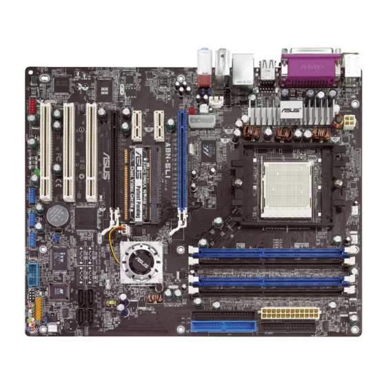
Page 14: Motherboard Layout
1.2.3 1.2.3 1.2.3 Motherboard layout Motherboard layout Motherboard layout 1.2.3 1.2.3 Motherboard layout Motherboard layout 24.5cm (9.6in) PS/2KBMS T: Mouse CPU_FAN CHA2_FAN B: Keyboard ATX12V SPDIF_O SPDIF_O2 USB12 LAN1_USB34 Top:Rear Speaker Out Center: Side Speaker Out Below: Center/Subwoofer ® Marvell Top:Line In 88E1111 Center:Line Out... -
Page 15: Layout Contents
1.2.4 1.2.4 1.2.4 Layout contents Layout contents Layout contents 1.2.4 1.2.4 Layout contents Layout contents S l o t s S l o t s S l o t s S l o t s S l o t s P a g e P a g e P a g e... - Page 16 I n t e r n a l c o n n e c t o r s I n t e r n a l c o n n e c t o r s I n t e r n a l c o n n e c t o r s I n t e r n a l c o n n e c t o r s I n t e r n a l c o n n e c t o r s P a g e...
-
Page 17: Central Processing Unit (Cpu)
Central Processing Unit (CPU) The motherboard comes with a surface mount 939-pin Zero Insertion Force (ZIF) socket designed for the AMD Athlon™ 64FX or AMD Athlon™ 64 processor. The 128-bit-wide data paths of these processors can run applications faster than processors with only 32-bit or 64-bit wide data paths. Take note of the marked corner (with gold triangle) on the CPU. - Page 18 Unlock the socket by pressing the lever sideways, then lift it up to a 90°-100° angle. S o c k e t l e v e r S o c k e t l e v e r S o c k e t l e v e r S o c k e t l e v e r S o c k e t l e v e r Make sure that the socket lever is lifted up to 90°-100°...
-
Page 19: Installing The Heatsink And Fan
1.3.2 1.3.2 1.3.2 1.3.2 1.3.2 Installing the heatsink and fan Installing the heatsink and fan Installing the heatsink and fan Installing the heatsink and fan Installing the heatsink and fan The AMD Athlon™ 64FX or AMD Athlon™ 64 processor requires a specially designed heatsink and fan assembly to ensure optimum thermal condition and performance. - Page 20 Attach one end of the retention bracket to the retention module base. Align the other end of the retention bracket (near the retention bracket lock) to the retention module base. A clicking sound denotes that the retention bracket is in place. Make sure that the fan and heatsink assembly perfectly fits the retention mechanism...
- Page 21 When the fan and heatsink assembly is in place, connect the CPU fan cable to the connector on the motherboard labeled CPU_FAN. CPU_FAN A8N-SLI ® A8N-SLI CPU fan connector Do not forget to connect the CPU fan connector! Hardware monitoring errors can occur if you fail to plug this connector.
-
Page 22: System Memory
System memory 1.4.1 1.4.1 1.4.1 1.4.1 1.4.1 Overview Overview Overview Overview Overview The motherboard comes with four 184-pin Double Data Rate (DDR) Dual Inline Memory Modules (DIMM) sockets. The following figure illustrates the location of the sockets: A8N-SLI ® A8N-SLI 184-pin DDR DIMM sockets C h a n n e l C h a n n e l S o c k e t s... -
Page 23: Installing A Dimm
1.4.3 1.4.3 Installing a DIMM Installing a DIMM 1.4.3 1.4.3 1.4.3 Installing a DIMM Installing a DIMM Installing a DIMM Make sure to unplug the power supply before adding or removing DIMMs or other system components. Failure to do so may cause severe damage to both the motherboard and the components. -
Page 24: Expansion Slots
Expansion slots In the future, you may need to install expansion cards. The following sub-sections describe the slots and the expansion cards that they support. Make sure to unplug the power cord before adding or removing expansion cards. Failure to do so may cause you physical injury and damage motherboard components. - Page 25 Standard interrupt assignments Standard interrupt assignments Standard interrupt assignments Standard interrupt assignments Standard interrupt assignments I R Q I R Q I R Q P r i o r i t y P r i o r i t y P r i o r i t y S t a n d a r d F u n c t i o n S t a n d a r d F u n c t i o n...
-
Page 26: Pci Slots
1.5.3 1.5.3 1.5.3 PCI slots PCI slots PCI slots 1.5.3 1.5.3 PCI slots PCI slots The PCI slots support cards such as a LAN card, SCSI card, USB card, and other cards that comply with PCI specifications. The figure shows a LAN card installed on a PCI slot. -
Page 27: Jumper
Jumper C l e a r R T C R A M ( C L R T C ) C l e a r R T C R A M ( C L R T C ) C l e a r R T C R A M ( C L R T C ) C l e a r R T C R A M ( C L R T C ) C l e a r R T C R A M ( C L R T C ) This jumper allows you to clear the Real Time Clock (RTC) RAM in CMOS. -
Page 28: Connectors
Connectors 1.7.1 1.7.1 1.7.1 1.7.1 1.7.1 Rear panel connectors Rear panel connectors Rear panel connectors Rear panel connectors Rear panel connectors 1 . 1 . P S / 2 m o u s e p o r t ( g r e e n ) . P S / 2 m o u s e p o r t ( g r e e n ) . - Page 29 8 . 8 . M i c r o p h o n e p o r t ( p i n k ) . M i c r o p h o n e p o r t ( p i n k ) . This port connects a microphone. M i c r o p h o n e p o r t ( p i n k ) .
-
Page 30: Internal Connectors
1.7.2 1.7.2 1.7.2 Internal connectors Internal connectors Internal connectors 1.7.2 1.7.2 Internal connectors Internal connectors 1 . 1 . F l o p p y d i s k d r i v e c o n n e c t o r ( 3 4 - 1 p i n F L O P P Y ) F l o p p y d i s k d r i v e c o n n e c t o r ( 3 4 - 1 p i n F L O P P Y ) F l o p p y d i s k d r i v e c o n n e c t o r ( 3 4 - 1 p i n F L O P P Y ) F l o p p y d i s k d r i v e c o n n e c t o r ( 3 4 - 1 p i n F L O P P Y ) -
Page 31: Jumper Settings
3 . 3 . I D E c o n n e c t o r s ( 4 0 - 1 p i n P R I _ I D E , S E C _ I D E ) I D E c o n n e c t o r s ( 4 0 - 1 p i n P R I _ I D E , S E C _ I D E ) I D E c o n n e c t o r s ( 4 0 - 1 p i n P R I _ I D E , S E C _ I D E ) I D E c o n n e c t o r s ( 4 0 - 1 p i n P R I _ I D E , S E C _ I D E ) - Page 32 4 . 4 . S e r i a l A T A c o n n e c t o r s S e r i a l A T A c o n n e c t o r s S e r i a l A T A c o n n e c t o r s S e r i a l A T A c o n n e c t o r s S e r i a l A T A c o n n e c t o r s...
- Page 33 5 . 5 . C P U , c h a s s i s , p o w e r , a n d c h i p s e t f a n c o n n e c t o r s ( 3 - p i n C P U , c h a s s i s , p o w e r , a n d c h i p s e t f a n c o n n e c t o r s ( 3 - p i n C P U , c h a s s i s , p o w e r , a n d c h i p s e t f a n c o n n e c t o r s ( 3 - p i n C P U , c h a s s i s , p o w e r , a n d c h i p s e t f a n c o n n e c t o r s ( 3 - p i n...
- Page 34 6 . 6 . U S B c o n n e c t o r s ( 1 0 - 1 p i n U S B 7 8 , U S B 5 6 , U S B 9 1 0 ) U S B c o n n e c t o r s ( 1 0 - 1 p i n U S B 7 8 , U S B 5 6 , U S B 9 1 0 ) U S B c o n n e c t o r s ( 1 0 - 1 p i n U S B 7 8 , U S B 5 6 , U S B 9 1 0 ) U S B c o n n e c t o r s ( 1 0 - 1 p i n U S B 7 8 , U S B 5 6 , U S B 9 1 0 )
- Page 35 8 . 8 . A T X p o w e r c o n n e c t o r s ( 2 4 - p i n E A T X P W R , 4 - p i n A T X 1 2 V 1 , A T X p o w e r c o n n e c t o r s ( 2 4 - p i n E A T X P W R , 4 - p i n A T X 1 2 V 1 , A T X p o w e r c o n n e c t o r s ( 2 4 - p i n E A T X P W R , 4 - p i n A T X 1 2 V 1 , A T X p o w e r c o n n e c t o r s ( 2 4 - p i n E A T X P W R , 4 - p i n A T X 1 2 V 1 ,...
- Page 36 9 . 9 . I n t e r n a l a u d i o c o n n e c t o r s ( 4 - p i n A U X , 4 - p i n C D ) I n t e r n a l a u d i o c o n n e c t o r s ( 4 - p i n A U X , 4 - p i n C D ) I n t e r n a l a u d i o c o n n e c t o r s ( 4 - p i n A U X , 4 - p i n C D ) I n t e r n a l a u d i o c o n n e c t o r s ( 4 - p i n A U X , 4 - p i n C D )
- Page 37 1 1 . 1 1 . 1 1 . 1 1 . 1 1 . C h a s s i s i n t r u s i o n c o n n e c t o r ( 4 - 1 p i n C H A S S I S ) C h a s s i s i n t r u s i o n c o n n e c t o r ( 4 - 1 p i n C H A S S I S ) C h a s s i s i n t r u s i o n c o n n e c t o r ( 4 - 1 p i n C H A S S I S ) C h a s s i s i n t r u s i o n c o n n e c t o r ( 4 - 1 p i n C H A S S I S )
-
Page 38: System Panel Connector
1 2 . 1 2 . S y s t e m p a n e l c o n n e c t o r ( 1 0 - 1 p i n F _ P A N E L ) 1 2 . -
Page 39: Chapter 2: Bios Setup
This chapter tells how to change the system settings through the BIOS Setup menus. Detailed descriptions of the BIOS parameters are also provided. BIOS setup... -
Page 40: Managing And Updating Your Bios
Copy the original motherboard BIOS using the ASUS Update or AFLASH utilities. -
Page 41: Awardbios Flash Utility
a. Insert a formatted, high density 1.44 MB floppy disk into the drive. b. Insert the Windows ® 2000 CD to the optical drive. c. Click S t a r t S t a r t S t a r t, then select R u n S t a r t R u n R u n... - Page 42 BIOS file and the Award BIOS Flash Utility. At the prompt, type AwardBIOS Flash Utility for ASUS V1.09 a w d f l a s h a w d f l a s h a w d f l a s h then press...
- Page 43 The utility verifies the AwardBIOS Flash Utility for ASUS V1.09 BIOS file in the floppy (C) Phoenix Technologies Ltd. All Rights Reserved disk and starts flashing For NF-KC804-A8N-SLI-00 DATE: 11/30/2004 the BIOS file. Flash Type - SST 49LF004A/B /3.3V File Name to Program: 1001-001.bin...
- Page 44 To save the current BIOS file using the AwardBIOS Flash Utility: Follow steps 1 to 6 of the previous section. Press <Y> when the utility prompts you to AwardBIOS Flash Utility for ASUS V1.09 (C) Phoenix Technologies Ltd. All Rights Reserved save the current BIOS For NF-KC804-A8N-SLI-00 DATE: 11/30/2004 file.
-
Page 45: Asus Crashfree Bios 2 Utility
ASUS CrashFree BIOS 2 utility ASUS CrashFree BIOS 2 utility The ASUS CrashFree BIOS is an auto recovery tool that allows you to restore the BIOS file when it fails or gets corrupted during the updating process. You can update a corrupted BIOS file using the motherboard support CD or the floppy disk that contains the updated BIOS file. -
Page 46: Bios Setup Program
BIOS Setup program This motherboard supports a programmable Flash ROM that you can update using the provided utility described in section “2.1 Managing and updating your BIOS.” Use the BIOS Setup program when you are installing a motherboard, reconfiguring your system, or prompted to “Run Setup.” This section explains how to configure your system using this utility. -
Page 47: Bios Menu Bar
2.2.1 2.2.1 2.2.1 BIOS menu bar BIOS menu bar BIOS menu bar 2.2.1 2.2.1 BIOS menu bar BIOS menu bar The top of the screen has a menu bar with the following selections: M A I N M A I N M A I N M A I N M A I N... - Page 48 General help General help General help General help General help In addition to the Item Specific Help window, the BIOS setup program also provides a General Help screen. You may launch this screen from any menu by simply pressing <F1>. The General Help screen lists the legend keys and their corresponding functions.
-
Page 49: Main Menu
Thu, Mar 17 2005 Item Specific Help Legacy Diskette A [1.44M, 3.5 in.] Change the internal clock. Primary IDE Master [ST320410A] Primary IDE Slave [ASUS CD--S520/] Secondary IDE Master [None] Secondary IDE Slave [None] First SATA Master [None] Second SATA Master [None]... -
Page 50: Primary And Secondary Ide Master/Slave
2.3.5 2.3.5 2.3.5 Primary and Secondary IDE Master/Slave Primary and Secondary IDE Master/Slave Primary and Secondary IDE Master/Slave 2.3.5 2.3.5 Primary and Secondary IDE Master/Slave Primary and Secondary IDE Master/Slave Primary IDE Master Select Menu Item Specific Help Auto Acoustic Management Disabled Press [Enter] to select. - Page 51 Capacity Capacity Capacity Capacity Capacity Displays the auto-detected hard disk capacity. This item is not configurable. Cylinder Cylinder Cylinder Cylinder Cylinder Shows the number of the hard disk cylinders. This item is not configurable. H e a d H e a d H e a d H e a d H e a d...
-
Page 52: First, Second, Third, And Fourth Sata Master
2.3.6 2.3.6 2.3.6 First, Second, Third, and Fourth SATA Master First, Second, Third, and Fourth SATA Master First, Second, Third, and Fourth SATA Master 2.3.6 2.3.6 First, Second, Third, and Fourth SATA Master First, Second, Third, and Fourth SATA Master First SATA Master Select Menu Auto Acoustic Management... -
Page 53: Installed Memory
Capacity Capacity Capacity Capacity Capacity Displays the auto-detected hard disk capacity. This item is not configurable. Cylinder Cylinder Cylinder Cylinder Cylinder Shows the number of the hard disk cylinders. This item is not configurable. H e a d H e a d H e a d H e a d H e a d... -
Page 54: Advanced Menu
Advanced Menu The Advanced menu items allow you to change the settings for the CPU and other system devices. Take caution when changing the settings of the Advanced menu items. Incorrect field values may cause the system to malfunction. Select Menu CPU Configuration Chipset Item Specific Help... -
Page 55: Cpu Configuration
2.4.1 2.4.1 2.4.1 2.4.1 2.4.1 CPU configuration CPU configuration CPU configuration CPU configuration CPU configuration The items in this menu show the CPU-related information auto-detected by the BIOS. Select Menu CPU Configuration Item Specific Help CPU Type AMD Athlon(tm) 64 Processor 3400+ CPU Speed 2200MHz Enable/Disable... -
Page 56: Chipset Configuration
2.4.2 2.4.2 2.4.2 Chipset configuration Chipset configuration Chipset configuration 2.4.2 2.4.2 Chipset configuration Chipset configuration The items in this menu show the chipset configuration settings. Select an item then press <Enter> to display a pop-up menu with the configuration options. Chipset Select Menu DRAM Configuration... - Page 57 Timing Mode [Auto] Sets the timing mode. Configuration options: [Auto] [Manual] Memclock index value [200Mhz] Sets the DRAM frequency. Configuration options: [100Mhz] [133Mhz] [166Mhz] [200Mhz] CAS# latency (Tcl) [2.5] Sets the CAS# latency. Configuration options: [2] [2.5] [3] Min RAS# active time (Tras) [8T] Sets the minimum RAS# active time.
-
Page 58: Pcipnp
MTRR mapping mode [Continuous] Sets the MTRR mapping mode. Configuration options: [Continuous] [Discrete] Errata 94 Enhanced [Auto] Errata 94 Enhanced [Auto] Errata 94 Enhanced [Auto] Errata 94 Enhanced [Auto] Errata 94 Enhanced [Auto] Configuration options: [Auto] [Disabled] 2.4.3 2.4.3 PCIPnP PCIPnP 2.4.3 2.4.3... - Page 59 When the item Resources Controlled By is set to [Auto], the item IRQ Resources is grayed out and is not configurable. Refer to the section “IRQ Resources” for information on how to enable this item. IRQ Resources IRQ Resources IRQ Resources IRQ Resources IRQ Resources R e s o u r c e s C o n t r o l l e d B y...
-
Page 60: Onboard Device Configuration
2.4.4 2.4.4 2.4.4 Onboard device configuration Onboard device configuration Onboard device configuration 2.4.4 2.4.4 Onboard device configuration Onboard device configuration The items in this menu show the onboard device configuration settings. Select an item then press <Enter> to display a pop-up menu with the configuration options. - Page 61 IDE Function Setup IDE Function Setup IDE Function Setup IDE Function Setup IDE Function Setup This sub-menu contains IDE function-related items. Select an item then press <Enter> to edit. IDE Function Setup Select Menu OnChip Channel0 [Enabled] Item Specific Help OnChip IDE Channel1 [Enabled] IDE DMA transfer access...
- Page 62 Serial-ATA 2 [Enabled] Allows you to enable or disable the Serial ATA 2 port. Configuration options: [Disabled] [Enabled] SATA2 DMA transfer [Enabled] Allows you to enable or disable the SATA2 DMA transfer access. Configuration options: [Disabled] [Enabled] IDE Prefetch Mode [Enabled] Allows you to enable or disable the IDE prefetch mode.
- Page 63 First, Second, Third, Fourth SATA Master RAID [Disabled] Enables or disables the RAID function of the first, second, third or fourth SATA master drive. Configuration options: [Enabled] [Disabled] USB configuration USB configuration USB configuration USB configuration USB configuration The items in this menu show the USB configuration settings. Select an item then press <Enter>...
- Page 64 Onboard LAN [Enabled] Onboard LAN [Enabled] Onboard LAN [Enabled] Onboard LAN [Enabled] Onboard LAN [Enabled] Allows you to enable or disable the onboard LAN controller. Keep the default [Enabled] if you wish to use the onboard LAN feature. Set to [Disabled] if you installed a PCI LAN card.
- Page 65 SLI configuration SLI configuration SLI configuration SLI configuration SLI configuration Select Menu SLI Configuration Item Specific Help EZ-Plug Warning [Enabled] EZ-Plug Warning [Enabled] EZ-Plug Warning [Enabled] EZ-Plug Warning [Enabled] EZ-Plug Warning [Enabled] EZ-Plug Warning [Enabled] Allows you to enable or disable the EZ-Plug warning feature. Configuration options: [Disabled] [Enabled] A S U S A 8 N - S L I A S U S A 8 N - S L I...
-
Page 66: Power Menu
Power Menu The Power menu allows you to reduce power consumption. This feature turns off the video display and shuts down the hard disk after a period of inactivity. Select Menu ACPI Suspend Type [S3(STR)] ACPI APIC Support [Enabled] Item Specific Help APM Configuration Hardware Monitor Select the ACPI state... -
Page 67: Apm Configuration
2.5.1 2.5.1 2.5.1 APM configuration APM configuration APM configuration 2.5.1 2.5.1 APM configuration APM configuration This menu shows the Advanced Power Management (APM) configuration settings. Select an item then press <Enter> to display a pop-up menu with the configuration options. Select Menu APM Configuration Item Specific Help... - Page 68 Power-On By Alarm [Disabled] Power-On By Alarm [Disabled] Power-On By Alarm [Disabled] Power-On By Alarm [Disabled] Power-On By Alarm [Disabled] Allows you to enable or disable RTC to generate a wake event. When this item is set to Enabled, the items Date of Month Alarm and Time (hh:mm:ss) Alarm items become user-configurable with set values.
-
Page 69: Hardware Monitor
2.5.2 2.5.2 2.5.2 Hardware monitor Hardware monitor Hardware monitor 2.5.2 2.5.2 Hardware monitor Hardware monitor This menu shows the hardware monitor settings auto-detected by the BIOS. Select Menu Hardware Monitor Item Specific Help Q-Fan Controller [Enabled] Vcore Voltage 1.50V Press [Enter] to enable 3.3V Voltage 3.31V or disable. -
Page 70: Boot Menu
CPU Target Temperature [66ºC] CPU Target Temperature [66ºC] CPU Target Temperature [66ºC] CPU Target Temperature [66ºC] CPU Target Temperature [66ºC] Allows you to set the CPU temperature threshold. When the CPU temperature reaches the value you set, the CPU fan runs at full speed. Configuration options: [51ºC] [54ºC] [57ºC] [60ºC] [63ºC] [66ºC] [69ºC] [72ºC] [75ºC] [78ºC] [81ºC] This item becomes configurable only when the Q - F a n C o n t r o l l e r... -
Page 71: Boot Device Priority
2.6.1 2.6.1 2.6.1 Boot Device Priority Boot Device Priority Boot Device Priority 2.6.1 2.6.1 Boot Device Priority Boot Device Priority Boot Device Priority Select Menu 1st Boot Device [CDROM] Item Specific Help 2nd Boot Device [Removable] Select your boot device 3rd Boot Device [Hard Disk] 4th Boot Device... -
Page 72: Boot Settings Configuration
2.6.3 2.6.3 2.6.3 Boot settings configuration Boot settings configuration Boot settings configuration 2.6.3 2.6.3 Boot settings configuration Boot settings configuration Boot Settings Configuration Select Menu Item Specific Help Case Open Warning [Disabled] Quick Boot [Enabled] Press [Enter] to enable Boot Up Floppy Seek [Enabled] or disable. - Page 73 Full Screen Logo [Enabled] Allows you to enable or disable the full screen logo display feature. Configuration options: [Disabled] [Enabled] Set this item to [Enabled] to use the ASUS MyLogo™ feature. Halt On [No Errors] Halt On [No Errors] Halt On [No Errors]...
-
Page 74: Security
2.6.4 2.6.4 2.6.4 Security Security Security 2.6.4 2.6.4 Security Security Security Select Menu Supervisor Password Clear Item Specific Help User Password Clear Password Check [Setup] Supervisor password controls full access. <Enter> to change password. Supervisor Password [Clear] Supervisor Password [Clear] Supervisor Password [Clear] Supervisor Password [Clear] Supervisor Password [Clear]... -
Page 75: Exit Menu
Forgot the password? If you forget your password, you can clear it by erasing the CMOS Real Time Clock (RTC) RAM. The RAM data containing the password information is powered by the onboard button cell battery. If you need to erase the CMOS RAM, refer to section “1.6 Jumpers” for instructions. - Page 76 Exit & Discard Changes Exit & Discard Changes Exit & Discard Changes Exit & Discard Changes Exit & Discard Changes Select this option only if you do not want to save the changes that you made to the Setup program. If you made changes to fields other than system date, system time, and password, the BIOS asks for a confirmation before exiting.
- Page 77 This chapter tells how to install SLI-ready PCI Express graphics cards. ® NVIDIA SLI™ technology support...
-
Page 78: Nvidia Nvidia
3.1.2 ASUS Certified SLI Graphics cards ASUS Certified SLI Graphics cards ASUS Certified SLI Graphics cards Use only ASUS certified PCI Express x16 SLI graphics cards to ensure optimum peformance. GeForce 6800 Ultra models GeForce 6800 Ultra models GeForce 6800 Ultra models... - Page 79 V e n d o r M o d e l N u m b e r M o d e l N u m b e r M o d e l N u m b e r ASUS EN6800GT BFG BFGO68256GTOCX eVGA...
-
Page 80: Dual Graphics Card Setup
Setting the ASUS EZ selector card Your motherboard package comes with a pre- installed ASUS EZ selector card. By default, the card is set for a single graphics card. To use two graphics cards on this motherboard, you must first set the... - Page 81 When released, pull the selector card out of the slot. Invert the selector card and D u a l D u a l insert the edge labeled D u a l D u a l D u a l V i d e o C a r d s V i d e o C a r d s V i d e o C a r d s V i d e o C a r d s.
-
Page 82: Installing Sli-Ready Graphics Cards
3.2.2 3.2.2 3.2.2 Installing SLI-ready graphics cards Installing SLI-ready graphics cards Installing SLI-ready graphics cards 3.2.2 3.2.2 Installing SLI-ready graphics cards Installing SLI-ready graphics cards Install only identical SLI-ready graphics cards that are NVIDIA ® certified. Different types of graphics cards will not work together properly. To install the graphics cards: Prepare two graphics cards. - Page 83 Insert one graphics card into the blue slot labeled P C I E X 1 6 _ 1 P C I E X 1 6 _ 1 P C I E X 1 6 _ 1 P C I E X 1 6 _ 1. Make P C I E X 1 6 _ 1 sure that the card is properly seated on the slot.
- Page 84 Align and insert the SLI connector to the goldfingers on each graphics card. Make sure that the connector is firmly in place. S L I c o n n e c t o r S L I c o n n e c t o r S L I c o n n e c t o r S L I c o n n e c t o r S L I c o n n e c t o r...
- Page 85 Remove any of the two bracket covers between the graphics cards. B r a c k e t s l o t B r a c k e t s l o t B r a c k e t s l o t B r a c k e t s l o t B r a c k e t s l o t Align and insert the retention...
-
Page 86: Installing The Device Drivers
3.2.3 3.2.3 3.2.3 Installing the device drivers Installing the device drivers Installing the device drivers 3.2.3 3.2.3 Installing the device drivers Installing the device drivers Refer to the documentation that came with your graphics card package to install the device drivers. Make sure that your PCI Express graphics card driver supports the NVIDIA SLI technology. - Page 87 From the nView Desktop Manager D e s k t o p D e s k t o p window, select the D e s k t o p D e s k t o p D e s k t o p M a n a g e m e n t M a n a g e m e n t M a n a g e m e n t...
- Page 88 Click the slider to display the following screen, then select the S L I S L I S L I S L I S L I m u l t i - G P U m u l t i - G P U m u l t i - G P U item.