Table of Contents
Advertisement
Advertisement
Table of Contents

Related Manuals for Asus A8N-VM


Summary of Contents for Asus A8N-VM
- Page 1 A8N-VM...
- Page 2 Product warranty or service will not be extended if: (1) the product is repaired, modified or altered, unless such repair, modification of alteration is authorized in writing by ASUS; or (2) the serial number of the product is defaced or missing.
-
Page 3: Table Of Contents
Contents Notices ... vi Safety information ... vii A8N-VM specifications summary ... viii Chapter 1: Product introduction Chapter 1: Product introduction Chapter 1: Product introduction Chapter 1: Product introduction Chapter 1: Product introduction Welcome! ... 1-2 Package contents ... 1-2 Special features ... - Page 4 Creating a bootable floppy disk ... 2-2 2.1.2 ASUS EZ Flash utility ... 2-3 2.1.3 AFUDOS utility ... 2-4 2.1.4 ASUS CrashFree BIOS 2 utility ... 2-6 2.1.5 ASUS Update utility ... 2-8 BIOS setup program ... 2-11 2.2.1 BIOS menu screen ... 2-12 2.2.2...
- Page 5 Running the support CD ... 3-2 3.2.2 Drivers menu ... 3-3 3.2.3 Utilities menu ... 3-4 3.2.4 Make Disk menu ... 3-5 3.2.5 Manual menu ... 3-6 3.2.6 ASUS Contact information ... 3-7 3.2.7 Other information ... 3-7 v v v v v...
-
Page 6: Notices
Notices Federal Communications Commission Statement Federal Communications Commission Statement Federal Communications Commission Statement Federal Communications Commission Statement Federal Communications Commission Statement This device complies with Part 15 of the FCC Rules. Operation is subject to the following two conditions: • This device may not cause harmful interference, and •... -
Page 7: Safety Information
Safety information Electrical safety Electrical safety Electrical safety Electrical safety Electrical safety • To prevent electrical shock hazard, disconnect the power cable from the electrical outlet before relocating the system. • When adding or removing devices to or from the system, ensure that the power cables for the devices are unplugged before the signal cables are connected. -
Page 8: A8N-Vm Specifications Summary
Supports Jack Sensing technology S/PDIF out interface Integrated 10/100 Mb MAC with Realtek external PHY Supports up to 8 USB 2.0 ports ASUS C.P.R. (CPU Parameter Recall) ASUS CrashFree BIOS 2 ASUS EZ Flash ASUS MyLogo2™ Stepless Frequency Selection (SFS) allows FSB tuning... - Page 9 A8N-VM specifications summary B I O S f e a t u r e s B I O S f e a t u r e s B I O S f e a t u r e s B I O S f e a t u r e s B I O S f e a t u r e s 4 Mb Flash ROM, AMI BIOS, PnP, DMI, WfM2.0, ACPI 2.0a,...
- Page 10 x x x x x...
- Page 11 This chapter describes the motherboard features and the new technologies it supports. Product introduction...
-
Page 12: Welcome
T h a n k y o u f o r b u y i n g a n A S U S The motherboard delivers a host of new features and latest technologies, making it another standout in the long line of ASUS quality motherboards! Before you start installing the motherboard, and hardware devices on it, check the items in your package with the list below. - Page 13 NVIDIA NVIDIA NVIDIA NVIDIA NVIDIA ® ® ® ® ® GeForce™ 6100 GPU GeForce™ 6100 GPU GeForce™ 6100 GPU GeForce™ 6100 GPU GeForce™ 6100 GPU and NVIDIA and NVIDIA and NVIDIA and NVIDIA and NVIDIA ® ® ® ® ® nForce™...
-
Page 14: Innovative Asus Features
ASUS EZ Flash BIOS ASUS EZ Flash BIOS With the ASUS EZ Flash, you can easily update the system BIOS even before loading the operating system. No need to use a DOS-based utility or boot from a floppy disk. See page 2-3 for details. -
Page 15: Before You Proceed
The illustration below shows the location of the onboard LED. ® A8N-VM Onboard LED A S U S A 8 N - V M A S U S A 8 N - V M A S U S A 8 N - V M... -
Page 16: Motherboard Overview
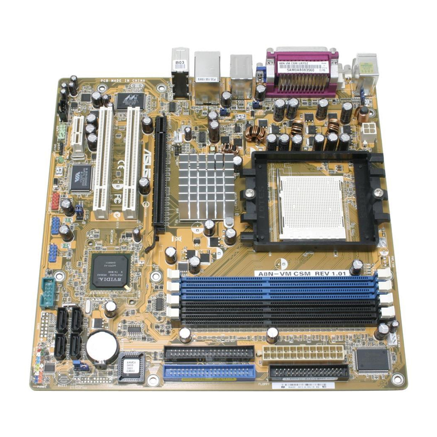
Motherboard overview 1.5.1 1.5.1 Motherboard layout Motherboard layout 1.5.1 1.5.1 1.5.1 Motherboard layout Motherboard layout Motherboard layout PS/2KBMS T: Mouse B: Keyboard KBPWR ATX12V USB12 LAN_USB12 Top:Line In Center:Line Out CHA_FAN Bottom:Mic In RTL8201CL PCIEX1_1 1986A AAFP SPDIF_OUT 1 - 6 1 - 6 1 - 6 1 - 6... -
Page 17: Placement Direction
1.5.2 1.5.2 1.5.2 Placement direction Placement direction Placement direction 1.5.2 1.5.2 Placement direction Placement direction When installing the motherboard, make sure that you place it into the chassis in the correct orientation. The edge with external ports goes to the rear part of the chassis as indicated in the image below. -
Page 18: Central Processing Unit (Cpu)
Installing the CPU Follow these steps to install a CPU. Locate the 939-pin ZIF socket on the motherboard. ® A8N-VM CPU Socket 939 Unlock the socket by pressing the lever sideways, then lift it up to a 90°-100° angle. Make sure that the socket lever is lifted up to 90°-100° angle, otherwise the CPU does not fit in completely. - Page 19 Connect the CPU fan cable to the CPU_FAN connector on the motherboard. ® A8N-VM CPU fan connector Do not forget to connect the CPU fan connector! Hardware monitoring errors can occur if you fail to plug this connector. A S U S A 8 N - V M...
-
Page 20: System Memory
Inline Memory Modules (DIMM) sockets. The following figure illustrates the location of the sockets: ® A8N-VM 184-pin DDR DIMM sockets C h a n n e l C h a n n e l C h a n n e l... - Page 21 (1)* Populated (2)* Populated * Use only identical DIMM pairs. Visit the ASUS website (www.asus.com) for the latest DDR 400 Qualified Vendors List for this motherboard. A S U S A 8 N - V M A S U S A 8 N - V M...
-
Page 22: Installing A Dimm
1.7.3 1.7.3 1.7.3 Installing a DIMM Installing a DIMM Installing a DIMM 1.7.3 1.7.3 Installing a DIMM Installing a DIMM Make sure to unplug the power supply before adding or removing DIMMs or other system components. Failure to do so may cause severe damage to both the motherboard and the components. -
Page 23: Expansion Slots
Expansion slots In the future, you may need to install expansion cards. The following sub-sections describe the slots and the expansion cards that they support. Make sure to unplug the power cord before adding or removing expansion cards. Failure to do so may cause you physical injury and damage motherboard components. - Page 24 Standard interrupt assignments Standard interrupt assignments Standard interrupt assignments Standard interrupt assignments Standard interrupt assignments I R Q I R Q P r i o r i t y P r i o r i t y I R Q I R Q I R Q P r i o r i t y...
-
Page 25: Pci Slots
1.8.3 1.8.3 1.8.3 PCI slots PCI slots PCI slots 1.8.3 1.8.3 PCI slots PCI slots The PCI slots support cards such as a LAN card, SCSI card, USB card, and other cards that comply with PCI specifications. The figure shows a LAN card installed on a PCI slot. -
Page 26: Jumpers
Removing the cap will cause system boot failure! ® A8N-VM Clear RTC RAM You do not need to clear the RTC when the system hangs due to overclocking. For system failure due to overclocking, use the C.P.R. (CPU Parameter Recall) feature. - Page 27 USBPW56 and USBPW78 jumper is for the internal USB connectors that you can connect to additional USB ports. ® A8N-VM USB device wake-up • The USB device wake-up feature requires a power supply that can provide 500mA on the +5VSB lead for each USB port; otherwise, the system will not power up.
- Page 28 Space Bar). This feature requires an ATX power supply that can supply at least 500 mA on the +5VSB lead, and a corresponding setting in the BIOS. ® A8N-VM Keyboard power setting 1 - 1 8 1 - 1 8 1 - 1 8...
-
Page 29: 1.10 Connectors
1.10 Connectors 1.10.1 Rear panel connectors 1.10.1 1.10.1 1.10.1 1.10.1 Rear panel connectors Rear panel connectors Rear panel connectors Rear panel connectors 1 . 1 . P S / 2 m o u s e p o r t ( g r e e n ) . P S / 2 m o u s e p o r t ( g r e e n ) . - Page 30 7 . 7 . U S B 2 . 0 p o r t s 3 a n d 4 . These two 4-pin Universal Serial Bus U S B 2 . 0 p o r t s 3 a n d 4 . U S B 2 .
-
Page 31: Internal Connectors
FDD cable with a covered Pin 5. ® A8N-VM Floppy disk drive connector 2 . 2 . C h a s s i s i n t r u s i o n c o n n e c t o r ( 4 - 1 p i n C H A S S I S ) -
Page 32: Jumper Settings
IDE cable. • Use the 80-conductor IDE cable for Ultra DMA 133/100/66 IDE devices. ® A8N-VM IDE connectors 1 - 2 2 1 - 2 2 1 - 2 2 1 - 2 2 1 - 2 2... - Page 33 (Ultra DMA/133) ® A8N-VM SATA connectors I m p o r t a n t n o t e o n S e r i a l A T A I m p o r t a n t n o t e o n S e r i a l A T A...
- Page 34 The S/PDIF module is purchased separately. ® A8N-VM Digital audio connector 1 - 2 4 1 - 2 4 1 - 2 4 1 - 2 4...
- Page 35 USB 2.0 specification that supports up to 480 Mbps connection speed. ® A8N-VM USB 2.0 connectors The USB 2.0 module is purchased separately. 8 . 8 . I n t e r n a l a u d i o c o n n e c t o r ( 4 - p i n C D )
- Page 36 Connect one end of the front panel audio I/O module cable to this connector. ® A8N-VM Analog front panel connector • We recommend that you connect a high-definition front panel audio module to this connector to avail of the motherboard high-definition audio capability.
- Page 37 You must install a PSU with a higher power rating if you intend to install additional devices. ® A8N-VM ATX power connectors A S U S A 8 N - V M A S U S A 8 N - V M...
-
Page 38: System Panel Connector
S y s t e m p a n e l c o n n e c t o r ( 2 0 - 1 p i n P A N E L ) This connector supports several chassis-mounted functions. ® A8N-VM System panel connector The sytem panel connector is color-coded for easy connection. Refer to the connector description below for details. - Page 39 This chapter tells how to change the system settings through the BIOS Setup menus. Detailed descriptions of the BIOS parameters are also provided. BIOS setup...
-
Page 40: Managing And Updating Your Bios
Refer to the corresponding sections for details on these utilities. Save a copy of the original motherboard BIOS file to a bootable floppy disk in case you need to restore the BIOS in the future. Copy the original motherboard BIOS using the ASUS Update or AFUDOS utilities. 2.1.1 2.1.1... -
Page 41: Asus Ez Flash Utility
ASUS EZ Flash utility ASUS EZ Flash utility The ASUS EZ Flash feature allows you to update the BIOS without having to go through the long process of booting from a floppy disk and using a DOS-based utility. The EZ Flash utility is built-in the BIOS chip so it is accessible by pressing <Alt>... -
Page 42: Afudos Utility
2.1.3 2.1.3 2.1.3 AFUDOS utility AFUDOS utility AFUDOS utility 2.1.3 2.1.3 AFUDOS utility AFUDOS utility The AFUDOS utility allows you to update the BIOS file in DOS environment using a bootable floppy disk with the updated BIOS file. This utility also allows you to copy the current BIOS file that you can use as backup when the BIOS fails or gets corrupted during the updating process. - Page 43 Updating the BIOS file To update the BIOS file using the AFUDOS utility: Visit the ASUS website (www.asus.com) and download the latest BIOS file for the motherboard. Save the BIOS file to a bootable floppy disk. Write the BIOS filename on a piece of paper. You need to type the exact BIOS filename at the DOS prompt.
-
Page 44: Asus Crashfree Bios 2 Utility
ASUS CrashFree BIOS 2 utility ASUS CrashFree BIOS 2 utility The ASUS CrashFree BIOS 2 is an auto recovery tool that allows you to restore the BIOS file when it fails or gets corrupted during the updating process. You can update a corrupted BIOS file using the motherboard support CD or the floppy disk that contains the updated BIOS file. - Page 45 Restart the system after the utility completes the updating process. The recovered BIOS may not be the latest BIOS version for this motherboard. Visit the ASUS website (www.asus.com) to download the latest BIOS file. A S U S A 8 N - V M...
-
Page 46: Asus Update Utility
2.1.5 2.1.5 ASUS Update utility ASUS Update utility The ASUS Update is a utility that allows you to manage, save, and update the motherboard BIOS in Windows allows you to: • Save the current BIOS file • Download the latest BIOS file from the Internet •... - Page 47 Updating the BIOS through the Internet To update the BIOS through the Internet: Launch the ASUS Update utility from the Windows S t a r t > P r o g r a m s S t a r t...
- Page 48 S t a r t A S U S U p d a t e A S U S U p d a t e. The ASUS Update main window appears. A S U S U p d a t e...
-
Page 49: Bios Setup Program
• Visit the ASUS website (www.asus.com) to download the latest BIOS file for this motherboard and . A S U S A 8 N - V M... -
Page 50: Bios Menu Screen
Boot Exit [10:55:25] [Thu 08/25/2005] [1.44M, 3.5 in] [ST320410A] [ASUS CD-S520/A] [Not Detected] [Not Detected] [Not Detected] [Not Detected] G e n e r a l h e l p G e n e r a l h e l p... -
Page 51: Menu Items
[10:55:25] System Date [Thu 08/ 25/2005] Legacy Diskette A [1.44M, 3.5 in.] Primary IDE Master [ST320410A] Primary IDE Slave [ASUS CD- S520/A] Secondary IDE Master [Not Detected] Secondary IDE Slave [Not Detected] v02.58 (C)Copyright 1985-2004, American Megatrends, Inc. First SATA... -
Page 52: Main Menu
2 - 1 4 BIOS SETUP UTILITY Power Boot Exit [10:55:25] [Thu 08/25/2005] [1.44M, 3.5 in] [ST320410A] [ASUS CD-S520/A] [Not Detected] [Not Detected] [Not Detected] [Not Detected] Use [ENTER], [TAB] or [SHIFT-TAB] to select a field. Use [+] or [-] to configure the System Time. -
Page 53: Primary And Secondary Ide Master/Slave; First And Second Sata
2.3.4 2.3.4 2.3.4 Primary and Secondary IDE Master/Slave; Primary and Secondary IDE Master/Slave; Primary and Secondary IDE Master/Slave; 2.3.4 2.3.4 Primary and Secondary IDE Master/Slave; Primary and Secondary IDE Master/Slave; First and Second SATA First and Second SATA First and Second SATA First and Second SATA First and Second SATA While entering Setup, the BIOS automatically detects the presence of IDE... -
Page 54: Ide Configuration
PIO Mode [Auto] PIO Mode [Auto] PIO Mode [Auto] PIO Mode [Auto] PIO Mode [Auto] Sets the PIO mode. Configuration options: [Auto] [0] [1] [2] [3] [4] DMA Mode [Auto] DMA Mode [Auto] DMA Mode [Auto] DMA Mode [Auto] DMA Mode [Auto] Sets the DMA mode. -
Page 55: System Information
2.3.6 2.3.6 2.3.6 System Information System Information System Information 2.3.6 2.3.6 System Information System Information This menu gives you an overview of the general system specifications. The BIOS automatically detects the items in this menu. Main AMIBIOS Version : 0112 Build Date : 09/07/05 Processor Type... -
Page 56: Advanced Menu
Advanced menu The Advanced menu items allow you to change the settings for the CPU and other system devices. Take caution when changing the settings of the Advanced menu items. Incorrect field values can cause the system to malfunction. Main Advanced AMD Cool ‘n’... -
Page 57: Jumperfree Configuration
2.4.2 2.4.2 JumperFree Configuration JumperFree Configuration 2.4.2 2.4.2 2.4.2 JumperFree Configuration JumperFree Configuration JumperFree Configuration Advanced AI Overclocking AI Overclocking [Auto] AI Overclocking [Auto] AI Overclocking [Auto] AI Overclocking [Auto] AI Overclocking [Auto] Allows you to select the overclocking options to achieve the desired CPU internal frequency. -
Page 58: Cpu Configuration
2.4.3 2.4.3 CPU Configuration CPU Configuration 2.4.3 2.4.3 2.4.3 CPU Configuration CPU Configuration CPU Configuration The items in this menu show the CPU-related information that the BIOS automatically detects. Advanced CPU Configuration Module Version: 14.06 Physical Count: 1 Logical Count: 1 AMD Athlon(tm) 64 Processor 3200+ Revision: D0 Cache L1: 64KB... - Page 59 Northbridge Configuration Northbridge Configuration Northbridge Configuration Northbridge Configuration Northbridge Configuration Advanced Northbridge Chipset Configuration Memory Configuration ECC Configuration NvigpBridge/C51G Configuration v02.58 (C)Copyright 1985-2004, American Megatrends, Inc. Memory Configuration Advanced Memory Configuration Memclock Mode MCT Timing Mode User Config Mode Burst Length Software Memory Hole A S U S A 8 N - V M A S U S A 8 N - V M...
- Page 60 M e m c l o c k M o d e [ A u t o ] M e m c l o c k M o d e [ A u t o ] M e m c l o c k M o d e [ A u t o ] M e m c l o c k M o d e [ A u t o ] M e m c l o c k M o d e [ A u t o ] [Auto] allows the BIOS to set the memclock mode automatically.
- Page 61 S o f t w a r e M e m o r y H o l e [ D i s a b l e d ] S o f t w a r e M e m o r y H o l e [ D i s a b l e d ] S o f t w a r e M e m o r y H o l e [ D i s a b l e d ] S o f t w a r e M e m o r y H o l e [ D i s a b l e d ] S o f t w a r e M e m o r y H o l e [ D i s a b l e d ]...
- Page 62 L 2 C a c h e B G S c r u b [ D i s a b l e d ] L 2 C a c h e B G S c r u b [ D i s a b l e d ] L 2 C a c h e B G S c r u b [ D i s a b l e d ] L 2 C a c h e B G S c r u b [ D i s a b l e d ] L 2 C a c h e B G S c r u b [ D i s a b l e d ]...
- Page 63 SouthBridge/MCP51 Chipset Configuration SouthBridge/MCP51 Chipset Configuration SouthBridge/MCP51 Chipset Configuration SouthBridge/MCP51 Chipset Configuration SouthBridge/MCP51 Chipset Configuration Advanced SouthBridge/MCP51 Chipset Configuration PCI Spread Spectrum HT Spread Spectrum PCI Spread Spectrum [Center Spread] Configuration options: [Disabled] [Center Spread] [Down Spread] HT Spread Spectrum [Center Spread] Configuration options: [Disabled] [Center Spread] [Down Spread] A S U S A 8 N - V M A S U S A 8 N - V M...
- Page 64 Hyper Transport Configuration Hyper Transport Configuration Hyper Transport Configuration Hyper Transport Configuration Hyper Transport Configuration Advanced Hyper Transport C51G Configuration LDT (K8) to C51G (NB) Frequency LDT (K8) to C51G (NB) LinkWidth Hyper Transport MCP51 Configuration MCP51(SB) to NVIDIA (NB) Frequency [800 MHz] MCP51(SB) to NVIDIA (NB) LinkWidth [8 v02.58 (C)Copyright 1985-2004, American Megatrends, Inc.
-
Page 65: Onboard Devices Configuration
2.4.5 2.4.5 Onboard Devices Configuration Onboard Devices Configuration 2.4.5 2.4.5 2.4.5 Onboard Devices Configuration Onboard Devices Configuration Onboard Devices Configuration Advanced Configure Winbond W83627EHG-A Super IO Chipset Serial Port1 Address Parallel Port Address Parallel Port Mode ECP Mode DMA Channel Parallel Port IRQ Onboard LAN Onboard LAN Boot ROM... -
Page 66: Pci Pnp
Onboard AUDIO [Enabled] Onboard AUDIO [Enabled] Onboard AUDIO [Enabled] Onboard AUDIO [Enabled] Onboard AUDIO [Enabled] Allows you to enable or disable the onboard high definition audio controller. Configuration options: [Enabled] [Disabled] 2.4.6 2.4.6 2.4.6 PCI PnP PCI PnP PCI PnP 2.4.6 2.4.6 PCI PnP... -
Page 67: Usb Configuration
Palette Snooping [Disabled] Palette Snooping [Disabled] Palette Snooping [Disabled] Palette Snooping [Disabled] Palette Snooping [Disabled] When set to [Enabled], the palette snooping feature informs the PCI devices that an ISA graphics device is installed in the system so that the latter can function correctly. -
Page 68: Power Menu
Power menu The Power menu items allow you to change the settings for the Advanced Power Management (APM). Select an item then press <Enter> to display the configuration options. Main Advanced Suspend Mode Repost Video on S3 Resume ACPI 2.0 Support ACPI APIC Support APM Configuration Hardware Monitor... -
Page 69: Apm Configuration
2.5.5 2.5.5 2.5.5 2.5.5 2.5.5 APM Configuration APM Configuration APM Configuration APM Configuration APM Configuration Power Power Button Mode Resume On PME# Resume On Ring Resume On LAN(MAC) Resume On RTC Alarm Resume On PS/2 Keyboard Resume On PS/2 Mouse Restore on AC Power Loss v02.58 (C)Copyright 1985-2004, American Megatrends, Inc. -
Page 70: Hardware Monitor
Power On By PS/2 Keyboard [Disabled] Power On By PS/2 Keyboard [Disabled] Power On By PS/2 Keyboard [Disabled] Power On By PS/2 Keyboard [Disabled] Power On By PS/2 Keyboard [Disabled] When set to [Enabled], this parameter allows you to use the PS/2 keyboard to turn on the system. - Page 71 CPU Q-Fan Control [Disabled] CPU Q-Fan Control [Disabled] CPU Q-Fan Control [Disabled] Allows you to enable or disable the ASUS Q-Fan feature that smartly adjusts the fan speeds for more efficient system operation. Configuration options: [Ignored] [Enabled] CPU Target Temperature [XXXºC] CPU Target Temperature [XXXºC]...
-
Page 72: Boot Menu
BIOS SETUP UTILITY Power Boot Exit BIOS SETUP UTILITY Boot [1st FLOPPY DRIVE] [PM-ST320410A] [PS-ASUS CD-S520/A] [NVIDIA Boot Agent] Specifies the Boot Device Boot Priority sequence. A virtual floppy disk drive (Floppy Drive B:) may appear when you set the CD-ROM drive as the first boot device. -
Page 73: Boot Settings Configuration
This allows you to enable or disable the full screen logo display feature. Configuration options: [Disabled] [Enabled] Set this item to [Enabled] to use the ASUS MyLogo2™ feature. Add On ROM Display Mode [Force BIOS] Add On ROM Display Mode [Force BIOS]... -
Page 74: Security
Hit ‘DEL’ Message Display [Enabled] Hit ‘DEL’ Message Display [Enabled] Hit ‘DEL’ Message Display [Enabled] Hit ‘DEL’ Message Display [Enabled] Hit ‘DEL’ Message Display [Enabled] When set to Enabled, the system displays the message “Press DEL to run Setup” during POST. Configuration options: [Disabled] [Enabled] Interrupt 19 Capture [Disabled] Interrupt 19 Capture [Disabled] Interrupt 19 Capture [Disabled]... - Page 75 To clear the supervisor password, select the Change Supervisor Password then press <Enter>. The message “Password Uninstalled” appears. If you forget your BIOS password, you can clear it by erasing the CMOS Real Time Clock (RTC) RAM. See section “1.9 Jumpers” for information on how to erase the RTC RAM.
-
Page 76: Exit Menu
To set a User Password: Select the Change User Password item and press <Enter>. On the password box that appears, type a password composed of at least six letters and/or numbers, then press <Enter>. Confirm the password when prompted. The message “Password Installed” appears after you set your password successfully. - Page 77 Exit & Save Changes Exit & Save Changes Exit & Save Changes Exit & Save Changes Exit & Save Changes Once you are finished making your selections, choose this option from the Exit menu to ensure the values you selected are saved to the CMOS RAM. An onboard backup battery sustains the CMOS RAM so it stays on even when the PC is turned off.
- Page 78 2 - 4 0 2 - 4 0 2 - 4 0 2 - 4 0 2 - 4 0 C h a p t e r 2 : B I O S s e t u p C h a p t e r 2 : B I O S s e t u p C h a p t e r 2 : B I O S s e t u p C h a p t e r 2 : B I O S s e t u p C h a p t e r 2 : B I O S s e t u p...
- Page 79 This chapter describes the contents of the support CD that comes with the motherboard package. Software support...
-
Page 80: Installing An Operating System
The contents of the support CD are subject to change at any time without notice. Visit the ASUS website(www.asus.com) for updates. 3.2.1 3.2.1 Running the support CD Running the support CD 3.2.1... -
Page 81: Drivers Menu
3.2.2 3.2.2 3.2.2 Drivers menu Drivers menu Drivers menu 3.2.2 3.2.2 Drivers menu Drivers menu The drivers menu shows the available device drivers if the system detects installed devices. Install the necessary drivers to activate the devices. NVIDIA nForce Chipset Driver NVIDIA nForce Chipset Driver NVIDIA nForce Chipset Driver NVIDIA nForce Chipset Driver... -
Page 82: Utilities Menu
ASUS Update ASUS Update ASUS Update ASUS Update The ASUS Update utility allows you to update the motherboard BIOS in a Windows ® environment. This utility requires an Internet connection either through a network or an Internet Service Provider (ISP). -
Page 83: Make Disk Menu
Microsoft ® Windows DirectX ® 9.0c. If your system is Microsoft Pack 2-embedded, skip Microsoft Anti-virus utility Anti-virus utility Anti-virus utility Anti-virus utility Anti-virus utility The anti-virus utility scans, identifies, and removes computer viruses. View the online help for detailed information. The screen display and utilities option may not be the same for different operating system versions. -
Page 84: Manual Menu
3.2.5 3.2.5 3.2.5 Manual menu Manual menu Manual menu 3.2.5 3.2.5 Manual menu Manual menu The Manual menu contains a list of supplementary user manuals. Click an item to open the folder of the user manual. Most user manual files are in Portable Document Format (PDF). Install the Adobe ®... -
Page 85: Asus Contact Information
C o n t a c t C o n t a c t C o n t a c t tab to display the ASUS contact information. You can also find this information on the inside front cover of this user guide. - Page 86 Displays the support CD contents in graphical format. Technical support Form Technical support Form Technical support Form Technical support Form Technical support Form Displays the ASUS Technical Support Request Form that you have to fill out when requesting technical support. Filelist Filelist Filelist Filelist...