Table of Contents
Advertisement
Advertisement
Table of Contents

Related Manuals for Asus A8NE-FM


Summary of Contents for Asus A8NE-FM
- Page 1 A8NE-FM...
- Page 2 Product warranty or service will not be extended if: (1) the product is repaired, modified or altered, unless such repair, modification of alteration is authorized in writing by ASUS; or (2) the serial number of the product is defaced or missing.
-
Page 3: Table Of Contents
Contents Notices ....................v Safety information ................vi A8NE-FM specifications summary ............vii Chapter 1: Chapter 1: Hardware information Hardware information Chapter 1: Chapter 1: Chapter 1: Hardware information Hardware information Hardware information Before you proceed .............. 1-2 Motherboard overview ............1-3 1.2.1... - Page 4 Managing and updating your BIOS ........2-2 2.1.1 Creating a bootable floppy disk ......2-2 2.1.2 AwardBIOS Flash Utility .......... 2-3 2.1.3 ASUS CrashFree BIOS 2 utility ........ 2-7 BIOS Setup program ............. 2-8 2.2.1 BIOS menu bar ............2-9 2.2.2 Legend bar ............. 2-9 Main Menu ................
-
Page 5: Notices
Notices Federal Communications Commission Statement Federal Communications Commission Statement Federal Communications Commission Statement Federal Communications Commission Statement Federal Communications Commission Statement This device complies with Part 15 of the FCC Rules. Operation is subject to the following two conditions: • This device may not cause harmful interference, and •... -
Page 6: Safety Information
Safety information Electrical safety Electrical safety Electrical safety Electrical safety Electrical safety • To prevent electrical shock hazard, disconnect the power cable from the electrical outlet before relocating the system. • When adding or removing devices to or from the system, ensure that the power cables for the devices are unplugged before the signal cables are connected. -
Page 7: A8Ne-Fm Specifications Summary
4 Mb Flash ROM, Award BIOS, LPC ASUS My Logo™ Special features ASUS EZ Flash ASUS Crash Free BIOS 2 ASUS CPU Overheating Protection (C.O.P.) Rear panel 1 x PS/2 mouse port 1 x Parallel port 1 x IEEE 1394a port 1 x LAN (RJ-45) port 4 x USB 2.0 ports... - Page 8 A8NE-FM specifications summary I n t e r n a l I n t e r n a l I n t e r n a l I n t e r n a l I n t e r n a l...
- Page 9 This chapter lists the hardware setup procedures that you have to perform when installing system components. It includes description of the jumpers and connectors on the motherboard. Hardware information...
-
Page 10: Before You Proceed
Before you proceed Take note of the following precautions before you install motherboard components or change any motherboard settings. • Unplug the power cord from the wall socket before touching any component. • Use a grounded wrist strap or touch a safely grounded object or a metal object, such as the power supply case, before handling components to avoid damaging them due to static electricity •... -
Page 11: Motherboard Overview
A8NE-FM ®... -
Page 12: Motherboard Layout
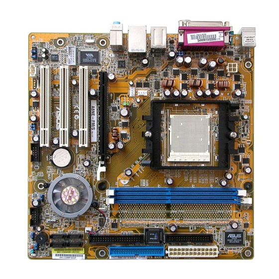
ASUS A8000 COM1 ATX12V ATX12V SPDIF_O F_USB12 BIOS USBLANCON SYS_FAN CPU_FAN Top:Line In Top:Line In Center:Line Out Bottom:Mic In PCIESLOT1 A8NE-FM CHIP_FAN PCI_SLOT1 nVIDIA CK804 IE1394_2 PCI_SLOT2 CR2032 3V Lithium Cell CMOS Power ® ACL655 PCI_SLOT3 BIOS_R BUZZER1 FAUDIO CLPSW... -
Page 13: Layout Contents
1.2.4 1.2.4 Layout contents Layout contents 1.2.4 1.2.4 1.2.4 Layout contents Layout contents Layout contents S l o t s S l o t s S l o t s P a g e P a g e P a g e S l o t s S l o t s P a g e... - Page 14 I n t e r n a l c o n n e c t o r s I n t e r n a l c o n n e c t o r s I n t e r n a l c o n n e c t o r s I n t e r n a l c o n n e c t o r s I n t e r n a l c o n n e c t o r s P a g e...
-
Page 15: Central Processing Unit (Cpu)
To install a CPU: Locate the CPU socket on the motherboard. A8NE-FM ® A8NE-FM CPU Socket 939 A S U S A 8 N E - F M A S U S A 8 N E - F M 1 - 7... - Page 16 Unlock the socket by pressing the lever sideways, then lift it up to a 90°-100° angle. S o c k e t l e v e r S o c k e t l e v e r S o c k e t l e v e r S o c k e t l e v e r S o c k e t l e v e r Make sure that the socket lever is lifted up to 90°-100°...
-
Page 17: Installing The Heatsink And Fan
1.3.2 1.3.2 1.3.2 1.3.2 1.3.2 Installing the heatsink and fan Installing the heatsink and fan Installing the heatsink and fan Installing the heatsink and fan Installing the heatsink and fan The AMD Athlon™ 64FX or AMD Athlon 64™ processor requires a specially designed heatsink and fan assembly to ensure optimum thermal condition and performance. - Page 18 Attach one end of the retention bracket to the retention module base. Align the other end of the retention bracket (near the retention bracket lock) to the retention module base. A clicking sound denotes that the retention bracket is in place. Make sure that the fan and heatsink assembly perfectly fits the retention mechanism...
- Page 19 CPU_FAN. CPU_FAN A8NE-FM ® A8NE-FM CPU fan connector Do not forget to connect the CPU fan connector! Hardware monitoring errors can occur if you fail to plug this connector. A S U S A 8 N E - F M...
-
Page 20: System Memory
Inline Memory Modules (DIMM) sockets. The following figure illustrates the location of the sockets: A8NE-FM ® A8NE-FM 184-pin DDR DIMM sockets C h a n n e l C h a n n e l S o c k e t s... -
Page 21: Installing A Dimm
1.4.3 1.4.3 Installing a DIMM Installing a DIMM 1.4.3 1.4.3 1.4.3 Installing a DIMM Installing a DIMM Installing a DIMM Make sure to unplug the power supply before adding or removing DIMMs or other system components. Failure to do so may cause severe damage to both the motherboard and the components. -
Page 22: Expansion Slots
Expansion slots In the future, you may need to install expansion cards. The following sub-sections describe the slots and the expansion cards that they support. Make sure to unplug the power cord before adding or removing expansion cards. Failure to do so may cause you physical injury and damage motherboard components. - Page 23 Standard interrupt assignments Standard interrupt assignments Standard interrupt assignments Standard interrupt assignments Standard interrupt assignments I R Q I R Q P r i o r i t y P r i o r i t y S t a n d a r d F u n c t i o n S t a n d a r d F u n c t i o n I R Q I R Q...
-
Page 24: Pci Express X16 Slot
1.5.3 1.5.3 PCI slots PCI slots 1.5.3 1.5.3 1.5.3 PCI slots PCI slots PCI slots The PCI slots support cards such as a LAN card, SCSI card, USB card, and other cards that comply with PCI specifications. The figure shows a LAN card installed on a PCI slot. -
Page 25: Jumpers
A8NE-FM ® Normal Clear CMOS A8NE-FM Clear RTC RAM (Default) You do not need to clear the RTC when the system hangs due to overclocking. For system failure due to overclocking, use the C.P.R. (CPU Parameter Recall) feature. Shut down and reboot the system so the BIOS can automatically reset parameter settings to default values. - Page 26 USBPW78 USBPW56 A8NE-FM ® +5VSB A8NE-FM USB device wake up (Default) • The USB device wake-up feature requires a power supply that can provide 500 mA on the +5VSB lead for each USB port; otherwise, the system would not power up.
- Page 27 BIOS_R A8NE-FM ® Default Recovery A8NE-FM BIOS recovery jumper A S U S A 8 N E - F M A S U S A 8 N E - F M 1 - 1 9 1 - 1 9 A S U S A 8 N E - F M...
-
Page 28: Connectors
Connectors 1.7.1 1.7.1 1.7.1 1.7.1 1.7.1 Rear panel connectors Rear panel connectors Rear panel connectors Rear panel connectors Rear panel connectors 1 . 1 . P S / 2 m o u s e p o r t ( g r e e n ) . P S / 2 m o u s e p o r t ( g r e e n ) . - Page 29 8 . 8 . U S B 2 . 0 p o r t s 3 a n d 4 . U S B 2 . 0 p o r t s 3 a n d 4 . U S B 2 . 0 p o r t s 3 a n d 4 . U S B 2 .
-
Page 30: Internal Connectors
PIN 1 A8NE-FM ® A8NE-FM Floppy disk drive connector 1 - 2 2 1 - 2 2 C h a p t e r 1 : H a r d w a r e i n f o r m a t i o n... - Page 31 PIN 1. A8NE-FM ® PIN 1 A8NE-FM IDE connectors A S U S A 8 N E - F M A S U S A 8 N E - F M 1 - 2 3 1 - 2 3...
- Page 32 SATA1 SATA2 A8NE-FM SATA connectors I m p o r t a n t n o t e s o n S e r i a l A T A I m p o r t a n t n o t e s o n S e r i a l A T A...
- Page 33 CHIP_FAN PFAN_PWR A8NE-FM ® A8NE-FM Chip fan connector A S U S A 8 N E - F M A S U S A 8 N E - F M 1 - 2 5 1 - 2 5 A S U S A 8 N E - F M...
- Page 34 A8NE-FM USB78 USB56 ® A8NE-FM USB 2.0 connectors Never connect a 1 3 9 4 c a b l e 1 3 9 4 c a b l e 1 3 9 4 c a b l e 1 3 9 4 c a b l e to the USB connectors. Doing so will...
- Page 35 PSON# Ground Ground +3 Volts -12 Volts A8NE-FM ATX power connectors +3 Volts +3 Volts A S U S A 8 N E - F M A S U S A 8 N E - F M 1 - 2 7...
- Page 36 A8NE-FM FAUDIO ® A8NE-FM Front panel audio connector 1 - 2 8 1 - 2 8 C h a p t e r 1 : H a r d w a r e i n f o r m a t i o n...
- Page 37 FRONTPANEL A8NE-FM ® HDLED RESET A8NE-FM System panel connector The sytem panel connector is color-coded for easy connection. Refer to the connector description below for details. • S y s t e m p o w e r L E D ( G r e e n 2 - p i n P L E D )
- Page 38 1 - 3 0 1 - 3 0 C h a p t e r 1 : H a r d w a r e i n f o r m a t i o n C h a p t e r 1 : H a r d w a r e i n f o r m a t i o n 1 - 3 0 1 - 3 0 1 - 3 0...
-
Page 39: Bios Setup
This chapter tells how to change the system settings through the BIOS Setup menus. Detailed descriptions of the BIOS parameters are also provided. BIOS setup A S U S A 8 N E - F M A S U S A 8 N E - F M 2 - 1 2 - 1 A S U S A 8 N E - F M... -
Page 40: Managing And Updating Your Bios
Copy the original motherboard BIOS using the ASUS Update or AFLASH utilities. -
Page 41: Awardbios Flash Utility
Windows ® 2000 environment To create a set of boot disks for Windows ® 2000: a. Insert a formatted, high density 1.44 MB floppy disk into the drive. b. Insert the Windows ® 2000 CD to the optical drive. c. Click S t a r t S t a r t S t a r t S t a r t, then select R u n... - Page 42 BIOS file and the Award BIOS Flash Utility. At the prompt, type AwardBIOS Flash Utility for ASUS B107A a w d f l a s h a w d f l a s h a w d f l a s h then press...
- Page 43 The utility verifies the AwardBIOS Flash Utility for ASUS B107A BIOS file in the floppy (C) Phoenix Technologies Ltd. All Rights Reserved disk and starts flashing For NF-CK804-A8NE-FM-00 DATE: 10/14/2004 the BIOS file. Flash Type - PMC Pm49FL004T LPC/FWH File Name to Program: 1001.bin...
- Page 44 To save the current BIOS file using the AwardBIOS Flash Utility: Follow steps 1 to 6 of the previous section. Press <Y> when the utility prompts you to AwardBIOS Flash Utility for ASUS B107A (C) Phoenix Technologies Ltd. All Rights Reserved save the current BIOS For NF-CK804-A8NE-FM-00 DATE: 10/14/2004 file.
-
Page 45: Asus Crashfree Bios 2 Utility
ASUS CrashFree BIOS 2 utility ASUS CrashFree BIOS 2 utility The ASUS CrashFree BIOS is an auto recovery tool that allows you to restore the BIOS file when it fails or gets corrupted during the updating process. You can update a corrupted BIOS file using the motherboard support CD or the floppy disk that contains the updated BIOS file. -
Page 46: Bios Setup Program
BIOS Setup program This motherboard supports a programmable Flash ROM that you can update using the provided utility described in section “2.1 Managing and updating your BIOS.” Use the BIOS Setup program when you are installing a motherboard, reconfiguring your system, or prompted to “Run Setup.” This section explains how to configure your system using this utility. -
Page 47: Bios Menu Bar
2.2.1 2.2.1 2.2.1 BIOS menu bar BIOS menu bar BIOS menu bar 2.2.1 2.2.1 BIOS menu bar BIOS menu bar The top of the screen has a menu bar with the following selections: M A I N M A I N M A I N M A I N M A I N... - Page 48 General help General help General help General help General help In addition to the Item Specific Help window, the BIOS setup program also provides a General Help screen. You may launch this screen from any menu by simply pressing <F1>. The General Help screen lists the legend keys and their corresponding functions.
-
Page 49: Main Menu
Item Specific Help Legacy Diskette A [1.44M, 3.5 in.] Change the internal clock. Primary IDE Master [ST320410A] Primary IDE Slave [ASUS CD--S520/] Secondary IDE Master [None] Secondary IDE Slave [None] First SATA Master [None] Second SATA Master [None] Third SATA Master... -
Page 50: Primary And Secondary Ide Master/Slave
2.3.5 2.3.5 2.3.5 Primary and Secondary IDE Master/Slave Primary and Secondary IDE Master/Slave Primary and Secondary IDE Master/Slave 2.3.5 2.3.5 Primary and Secondary IDE Master/Slave Primary and Secondary IDE Master/Slave Primary IDE Master Select Menu Item Specific Help PIO Mode [Auto] UDMA Mode [Auto]... - Page 51 Primary IDE Master [Auto] Primary IDE Master [Auto] Primary IDE Master [Auto] Primary IDE Master [Auto] Primary IDE Master [Auto] Select [Auto] to automatically detect an IDE hard disk drive. If automatic detection is successful, Setup automatically fills in the correct values for the remaining fields on this sub-menu.
-
Page 52: First, Second, Third, And Fourth Sata Master
2.3.6 2.3.6 2.3.6 First, Second, Third, and Fourth SATA Master First, Second, Third, and Fourth SATA Master First, Second, Third, and Fourth SATA Master 2.3.6 2.3.6 First, Second, Third, and Fourth SATA Master First, Second, Third, and Fourth SATA Master Primary IDE Master Select Menu Item Specific Help... -
Page 53: Advanced Menu
Advanced Menu The Advanced menu items allow you to change the settings for the CPU and other system devices. Take caution when changing the settings of the Advanced menu items. Incorrect field values may cause the system to malfunction. Select Menu CPU Configuration Chipset Item Specific Help... -
Page 54: Cpu Configuration
2.4.1 2.4.1 2.4.1 CPU configuration CPU configuration CPU configuration 2.4.1 2.4.1 CPU configuration CPU configuration The items in this menu show the CPU-related information auto-detected by the BIOS. Select Menu CPU Configuration Item Specific Help CPU Type AMD Athlon(tm) 64 Processor 3400+ CPU Speed 2222MHz Cache RAM... -
Page 55: Chipset Configuration
2.4.2 2.4.2 2.4.2 Chipset configuration Chipset configuration Chipset configuration 2.4.2 2.4.2 Chipset configuration Chipset configuration The items in this menu show the chipset configuration settings. Select an item then press <Enter> to display a pop-up menu with the configuration options. Chipset Select Menu Item Specific Help... - Page 56 Max Memclock (MHz) [Auto] Sets the maximum operating memory clock. Configuration options: [Auto] [DDR200] [DDR266] [DDR333] [DDR400] CAS# latency (Tcl) [Auto] Sets the CAS# latency. Configuration options: [Auto] [2.0] [2.5] [3.0] RAS# to CAS# delay (Trcd) [Auto] Sets the RAS# to CAS# delay to Read/Write command on the same bank.
-
Page 57: Pcipnp
2.4.3 2.4.3 2.4.3 PCIPnP PCIPnP PCIPnP 2.4.3 2.4.3 PCIPnP PCIPnP The items in this menu show the PCIPnP configuration settings. Select an item then press <Enter> to display a pop-up menu with the configuration options. PCIPnP Select Menu Item Specific Help Plug &... -
Page 58: Onboard Device Configuration
Maximum Payload Size [4096] Maximum Payload Size [4096] Maximum Payload Size [4096] Maximum Payload Size [4096] Maximum Payload Size [4096] Sets the maximum TLP payload size (in bytes) for the PCI Express devices. Configuration options: [128] [256] [512] [1024] [2048] [4096] 2.4.4 2.4.4 2.4.4... - Page 59 IDE Function Setup IDE Function Setup IDE Function Setup IDE Function Setup IDE Function Setup This sub-menu contains IDE function-related items. Select an item then press <Enter> to edit. IDE Function Setup Select Menu Item Specific Help OnChip Channel0 [Enabled] OnChip IDE Channel1 [Enabled] IDE DMA transfer access...
- Page 60 Serial-ATA 1 [Enabled] Allows you to enable or disable the Serial ATA 1 port. Configuration options: [Disabled] [Enabled] SATA2 DMA transfer [Enabled] Allows you to enable or disable the SATA2 DMA transfer access. Configuration options: [Disabled] [Enabled] IDE Prefetch Mode [Enabled] Allows you to enable or disable the IDE prefetch mode.
- Page 61 First, Second, Third, Fourth SATA Master RAID [Disabled] Enables or disables the RAID function of the first, second, third or fourth SATA master drive. Configuration options: [Enabled] [Disabled] Onboard IEEE 1394 [Enabled] Onboard IEEE 1394 [Enabled] Onboard IEEE 1394 [Enabled] Onboard IEEE 1394 [Enabled] Onboard IEEE 1394 [Enabled] Allows you to enable or disable the onboard IEEE 1394 device support.
- Page 62 USB configuration USB configuration USB configuration USB configuration USB configuration The items in this menu show the USB configuration settings. Select an item then press <Enter> to display a pop-up menu with the configuration options. Select Menu USB Configuration Item Specific Help USB Controller [Enabled] USB 2.0 Controller...
-
Page 63: Power Menu
Power Menu The Power menu allows you to reduce power consumption. This feature turns off the video display and shuts down the hard disk after a period of inactivity. Select Menu ACPI Suspend Type [S1&S3] ACPI APIC Support [Enabled] Item Specific Help APM Configuration Select the ACPI Hardware Monitor... -
Page 64: Apm Configuration
2.5.1 2.5.1 2.5.1 APM configuration APM configuration APM configuration 2.5.1 2.5.1 APM configuration APM configuration This menu shows the Advanced Power Management (APM) configuration settings. Select an item then press <Enter> to display a pop-up menu with the configuration options. APM Configuration Select Menu Item Specific Help... - Page 65 WOR (RI#) From Soft-Off [Enabled] WOR (RI#) From Soft-Off [Enabled] WOR (RI#) From Soft-Off [Enabled] WOR (RI#) From Soft-Off [Enabled] WOR (RI#) From Soft-Off [Enabled] Allows you to enable or disable the Wake-On-Ring feature. This feature requires an ATX power supply that provides at least 1A on the +5VSB lead. Configuration options: [Disabled] [Enabled] Power-On By Alarm [Disabled] Power-On By Alarm [Disabled]...
-
Page 66: Hardware Monitor
2.5.2 2.5.2 2.5.2 Hardware monitor Hardware monitor Hardware monitor 2.5.2 2.5.2 Hardware monitor Hardware monitor This menu shows the hardware monitor settings auto-detected by the BIOS. Select Menu Hardware Monitor Item Specific Help CPU Temperature 48ºC M/B Temperature 38ºC 5Vsb 4.96V Vccp 1.58V... - Page 67 System Fan Low Voltage [5.0 V] System Fan Low Voltage [5.0 V] System Fan Low Voltage [5.0 V] System Fan Low Voltage [5.0 V] System Fan Low Voltage [5.0 V] Allows the user to select the system fan voltage for slower fan speed operation.
-
Page 68: Boot Menu
Boot Menu This Boot menu items allow you to change the system boot settings. Select an item then press <Enter> to display a pop-up menu with the configuration options. Select Menu Boot Device Priority Removable Drives Item Specific Help Hard Drisk Drives Select Boot Device CDROM Drives Priority... -
Page 69: Removable Drives
1st ~ xth Boot Device 1st ~ xth Boot Device 1st ~ xth Boot Device 1st ~ xth Boot Device 1st ~ xth Boot Device These items specify the boot device priority sequence from the available devices. The number of devices that appears on the screen depends on the number of devices installed in the system. -
Page 70: Cd-Rom Drives
2.6.4 CD-ROM drives CD-ROM drives CDROM Drives Select Menu Item Specific Help 1. 1st Slave: ASUS CD-S520/A Use <up> or <down> arrow to select a device, then press <+> to move it up, or <-> to move it down the list. Press <ESC>... - Page 71 Full Screen Logo [Enabled] Allows you to enable or disable the full screen logo display feature. Configuration options: [Disabled] [Enabled] Set this item to [Enabled] to use the ASUS MyLogo™ feature. Halt On [No Errors] Halt On [No Errors] Halt On [No Errors]...
-
Page 72: Security
2.6.6 2.6.6 2.6.6 Security Security Security 2.6.6 2.6.6 Security Security Security Select Menu Item Specific Help Supervisor Password Clear User Password Clear Supervisor password Password Check [Setup] controls full access, <Enter> to change password. Supervisor Password [Clear] Supervisor Password [Clear] Supervisor Password [Clear] Supervisor Password [Clear] Supervisor Password [Clear]... -
Page 73: Exit Menu
Forgot the password? If you forget your password, you can clear it by erasing the CMOS Real Time Clock (RTC) RAM. The RAM data containing the password information is powered by the onboard button cell battery. If you need to erase the CMOS RAM, refer to section “1.6 Jumpers” for instructions. - Page 74 Exit & Discard Changes Exit & Discard Changes Exit & Discard Changes Exit & Discard Changes Exit & Discard Changes Select this option only if you do not want to save the changes that you made to the Setup program. If you made changes to fields other than system date, system time, and password, the BIOS asks for a confirmation before exiting.