Table of Contents
Advertisement
GA-6FASV Series
Xeon Processor Motherboard
USER'S Manual
Xeon
*
The WEEE marking on the product indicates this product must not be disposed of with
user's other household waste and must be handed over to a designated collection point
for the recycling of waste electrical and electronic equipment!!
*
The WEEE marking applies only in European Union's member states.
Processor Motherboard
®
Rev. 1001
Advertisement
Table of Contents

Related Manuals for Gigabyte GA-6FASV1


Summary of Contents for Gigabyte GA-6FASV1
- Page 1 GA-6FASV Series Xeon Processor Motherboard USER’S Manual Xeon Processor Motherboard ® Rev. 1001 The WEEE marking on the product indicates this product must not be disposed of with user's other household waste and must be handed over to a designated collection point for the recycling of waste electrical and electronic equipment!! The WEEE marking applies only in European Union's member states.
-
Page 2: Table Of Contents
Item Checklist ..................4 Chapter 1Introduction ................5 1.1.Considerations Prior to Installation ............5 1.2.Features Summary ................6 1.3.GA-6FASV1/GA-6FASV2 Motherboard Component......8 Chapter 2Hardware Installation Process ..........10 2.1.Installing Processor and CPU Heat Sink ..........10 2.1.1.Installing CPU ......................10 2.1.2.Installing Cooling FAN .................... - Page 3 GA-6FASV Series Motherboard Boot ......................59 Exit ......................60...
-
Page 4: Item Checklist
Serial ATA cable x 2 I/O Shield Kit CD for motherboard driver & utility The GA-6FASV1/The GA-6FASV2 quick reference guide * The items listed above are for reference only, and are subject to change without notice. -
Page 5: Chapter 1Introduction
2. Damage as a result of violating the conditions recommended in the user manual. 3. Damage due to improper installation. 4. Damage due to use of uncertified components. 5. Damage due to use exceeding the permitted parameters. 6. Product determined to be an unofficial Gigabyte product. -
Page 6: Features Summary
GA-6FASV Series Motherboard 1.2. Features Summary Form Factor 9.6” x 9.6” Micro ATX size form factor, 6 layers PCB Supports single Intel LGA1156 (socket H1) processor ® Support Lynnfield (Quad-core) processor Enhanced Intel SpeedStep Technology (EIST) & Demand Based Switch (DBS) ... - Page 7 GA-6FASV Series Motherboard 2 x RJ45 LAN ports (GA-6FASV1) 1 x RJ45 LAN ports (GA-6FASV2) 1 x NMI switch Hardware Monitor Winbond W83627DHG-P controller Enhanced features with CPU Vcore, DDR3 1.5V, VCC3 (3.3V), 12V, 5V, and System Temperature Values viewing ...
-
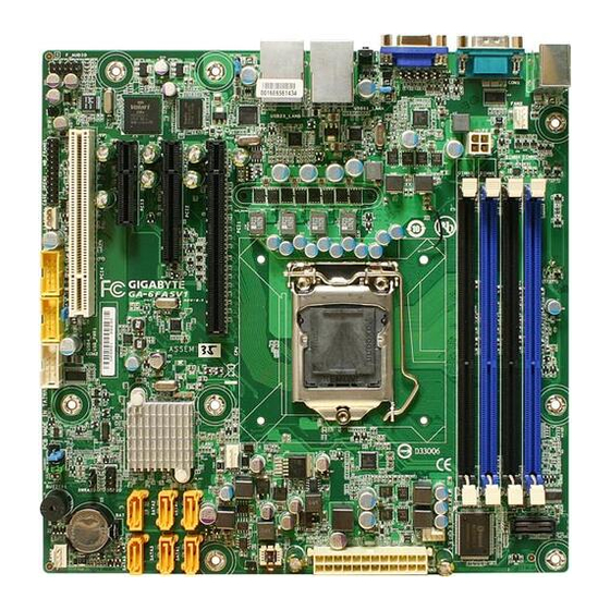
Page 8: Ga-6Fasv1/Ga-6Fasv2 Motherboard Component
PCI1 PCIe2.0 (5.0GT/s), x 16 Slot DIMM3/1 Channel A DDR3 sockets DIMM4/2 Channel B DDR3 sockets USB23_LANB** USB 2.0 and Gigabit LAN ports (GA-6FASV1) USB2.0 only (GA-6FASV2) USB01_LANA USB 2.0 and Gigabit LAN ports NMI_BTN NMI switch VGA port COM1... - Page 9 GA-6FASV Series Motherboard USB_PWR1 USB1 power source selection jumper USB_PWR2 USB2 power source selection jumper USB_PWR3 USB3 power source selection jumper 24 25...
-
Page 10: Chapter 2Hardware Installation Process
GA-6FASV Series Motherboard Chapter 2 Hardware Installation Process 2.1. Installing Processor and CPU Heat Sink Before installing the processor and cooling fan, adhere to the following cautions: 1. The processor will overheat without the heatsink and/or fan, resulting in permanent irreparable damage. -
Page 11: Installing Cooling Fan
GA-6FASV Series Motherboard 2.1.2. Installing Cooling FAN Step 1 Attach the cooling fan on the processor socket. Step 2 Turning and push vertically the push pin as arrow direction shown. Step 3 Connect processor fan cable connector to the processor fan connector. -
Page 12: Installing Memory Modules
GA-6FASV Series Motherboard 2.2. Installing memory modules Before installing the memory modules, please comply with the following conditions: 1. Please make sure that the memory is supported by the motherboard. It is recommended to use the memory with similar capacity, specifications and brand. 2. - Page 13 GA-6FASV Series Motherboard Memory Population Table Channel A Channel B Interleave Total mode Memory DIMM3 DIMM1 DIMM4 DIMM2 Single Channel Dual Channel 16GB...
-
Page 14: Connect Ribbon Cables, Cabinet Wires, And Power Supply
GA-6FASV Series Motherboard 2.3. Connect ribbon cables, cabinet wires, and power supply 2.3.1. I/O Back Panel Introduction GA-6FASV1 GA-6FASV2... - Page 15 GA-6FASV Series Motherboard PS/2 Keyboard and PS/2 Mouse Connector To install a PS/2 port keyboard and mouse, plug the mouse to the upper port (green) and the keyboard to the lower port (purple). Serial Port Connects to serial-based mouse or data processing devices. Video Port The video in port allows connect to video in, which can also apply to video loop thru function.
- Page 16 GA-6FASV Series Motherboard LAN LED Description LED2 (Green/Yellow) LED1 (Green) Name Color Condition Description LED1 Green LAN Link / no Access Green BLINK LAN Access Idle LED2 10Mbps connection Green BLINK Port identification with 10 Mbps connection Green 100Mbps connection Green BLINK Port identification with 100Mbps connection...
-
Page 17: Connectors And Jumper Setting Introduction
GA-6FASV Series Motherboard 2.4. Connectors and Jumper Setting Introduction 1. P1 14. FAN1 (CPU fan connector) 2. P2 15. FAN2 (System fan connector)) 3. COM2 16. FAN3 (System fan connector) 4. USB4_5 (USB cable connector) 17. FAN4 (System fan connector) 5. - Page 18 GA-6FASV Series Motherboard 1/2 ) P1/P2 (24-pin/ 4-pin ATX power connectors) With the use of the power connector, the power supply can supply enough stable power to all the components on the motherboard. Before connecting the power connector, please make sure that all components and devices are properly installed.
- Page 19 GA-6FASV Series Motherboard 3 ) COM2 Pin No. Definition DCD- SIN2 SOUT2 DTR2- DSR2- RTS2- CTS2- RI2- 4/5 ) USB4_5/USB10_11 (USB cable connectors) Be careful with the polarity of the front USB connector. Check the pin assignment carefully while you connect the front USB cable, incorrect connection between the cable and connector will make the device unable to work or even damage it.
- Page 20 GA-6FASV Series Motherboard 6 ) F_PANEL (2X12 Pins Front Panel connector) Please connect the power LED, PC speaker, reset switch and power switch of your chassis front panel to the F_PANEL connector according to the pin assignment above. Pin No. Signal Name Description Power LED +...
- Page 21 GA-6FASV Series Motherboard 7/8/9/10/11/12 ) SATA 0~5 (Serial ATA cable connectors) SATA 3Gb/s can provide up to 300MB/s transfer rate. Please refer to the BIOS setting for the SATA 3Gb/s and install the proper driver in order to work properly. Pin No.
- Page 22 GA-6FASV Series Motherboard 14/15/16/17 ) FAN1/2/3/4 (CPU fan/System fan cable connectors) The cooler fan power connector supplies a +12V power voltage via a 3-pin/4-pin(CPU_FAN) power connector and possesses a foolproof connection design. Most coolers are designed with color-coded power connector wires. A red power connector wire indicates a positive connection and requires a +12V power voltage.
- Page 23 GA-6FASV Series Motherboard Jumper Setting...
- Page 24 GA-6FASV Series Motherboard 19 ) CLR_CMOS1 (Clear CMOS jumper) You may clear the CMOS data to its default values by this jumper. To clear CMOS, temporarily short 2-3 pin. 1-2 close: Normal operation (Default setting) 2-3 close: Clear CMOS 20 ) PASSWORD1 (Set Supervisor password jumper) 1-2 Close: Set Supervisor Password.
-
Page 25: Chapter 3Bios Setup
GA-6FASV Series Motherboard Chapter 3 BIOS Setup BIOS (Basic Input and Output System) includes a CMOS SETUP utility which allows user to configure required settings or to activate certain system features. The CMOS SETUP saves the configuration in the CMOS SRAM of the motherboard. When the power is turned off, the battery on the motherboard supplies the necessary power to the CMOS SRAM. -
Page 26: Getting Help
GA-6FASV Series Motherboard GETTING HELP Main Menu The on-line description of the highlighted setup function is displayed at the bottom of the screen. Status Page Setup Menu / Option Page Setup Menu Press F1 to pop up a small help window that describes the appropriate keys to use and the possible selections for the highlighted item. -
Page 27: Main
GA-6FASV Series Motherboard Main Once you enter Phoenix BIOS Setup Utility, the Main Menu (Figure 1) will appear on the screen. Use arrow keys to select among the items and press <Enter> to accept or enter the sub-menu. Figure 1: Main System Date Set the System Date. -
Page 28: Total Memory
GA-6FASV Series Motherboard Processor Information This category includes the information of CPU type, Speed ,and number of CPU count. Total Memory The BIOS determines how much total memory is present during the POST. -
Page 29: Advanced
GA-6FASV Series Motherboard Advanced About This Section: Advanced With this section, allowing user to configure your system for advanced operation. User can set the Processor configuration, Memory configuration, Advanced chipset control, PCI configuration, SATA configuration, Peripheral configuration, Boot configuration, and Hardware Monitor. -
Page 30: Processor Setting
GA-6FASV Series Motherboard Processor Setting... -
Page 31: Execute Disable Bit
GA-6FASV Series Motherboard Processor Setting This category includes the information of CPU Speed, Processor ID ,Processor L2 / L3 Cache. And setup sub-menu for CPU Power Management. Please note that setup menu options will be variable depends on the type of CPU. Multiprocessor Specification This option allows user to configure the multiprocessor(MP) specification revision level. -
Page 32: Active Processor Cores
GA-6FASV Series Motherboard Active Processor Cores Options One Core, Two cores, Max Cores. Default setting is Max Cores. Hyper-Threading Technology Enabled Enable Intel Hyper Threading Technology. Disabled Disable Intel Hyper Threading Technology. (Default setting) A20M Support Enabled Enable A20M Support. (Default setting) Disabled Disable A20M Support... -
Page 33: Power Management
GA-6FASV Series Motherboard Power Management Figure 2-1-1: Power Management EIST (GV3) & C State Enabled Enable EIST (GV3) and C State items. (Default setting) Disabled Disable EIST (GV3) and C State items. Intel Speedstep(R) Technology Enabled Enable Intel Speedstep(R) Technology. (Default setting) Disabled Disable Intel Speedstep(R) Technology. -
Page 34: Turbo Mode
GA-6FASV Series Motherboard SW_ALL In SW_ALL mode, the OS Power Manager is responsible for coordinating the P-state among logical processors with dependencies and must initiate the transition on all of those Logical Processors. SW_ANY In SW_ANY mode, the OS Power Manager is responsible for coordinating the P-state among logical processors with dependencies and may initiate the transition on any of those Logical Processors . -
Page 35: Package C State Limit
GA-6FASV Series Motherboard state. Disabled Disable CPU C6 Report. (Default setting) Package C State Limit Desired state for the C-State package limit. Options C0, C1 State, C3 State, C6 State, No Limit. The default setting is No Limit. Default setting is No Limit. ACPI MWAIT extensions Enabled CST using MWAIT extension is enabled for OSPM use. -
Page 36: Memory Configuration
GA-6FASV Series Motherboard Memory Configuration Figure 2-2: Memory Configuration Base Memory/Extended Memory/Memory Frequency/DIMM Status These category is display-only which is determined by POST (Power On Self Test) of the BIOS. Memory Reset Select ‘Yes’, system will clear the memory error status. Save the changes and restart system. -
Page 37: Advanced Chipset Configuration
GA-6FASV Series Motherboard Advanced Chipset Configuration Figure 2-3: Advanced Chipset Configuration... - Page 38 GA-6FASV Series Motherboard Figure 2-3-1: Intel VT for Directed I/O (VT-d)
- Page 39 GA-6FASV Series Motherboard Intel VT for Directed I/O (VT-d) Enabled Enable Intel VT for Directed I/O (VT-d). (Default setting) Disabled Disable Intel VT for Directed I/O (VT-d). Advanced Chipset Control Main Menu Options QPI Control Settings Enabled Enable QPI Control settings. Disabled Disable QPI Control settings.
-
Page 40: Pci Configuration
GA-6FASV Series Motherboard PCI Configuration Figure 2-4: PCI Configuration PCI Slot 1/2/3/4 Option ROM Enabled Enable this item to initialize device expansion ROM. (Default setting) Disabled Disable this function. Onboard LAN1 Controller Enabled Enable Onboard LAN controller. (Default setting) Disabled Disable this function. - Page 41 GA-6FASV Series Motherboard LAN2Option ROM Scan Enabled Enable onboard LAN2 device and initialize device expansion ROM. Disabled Disable this function. (Default setting)
-
Page 42: Sata Configuration
GA-6FASV Series Motherboard SATA Configuration Figure 2-5: SATA Configuration Serial ATA Enabled Enables on-board serial ATA function. (Default setting) Disabled Disables on-board serial ATA function. SATA Mode Selection Determine IDE as the SATA mode. (Default setting) RAID Enable the SATA RAID function. ACHI Set this item to enable SATA AHCI function for WinXP-SP1+IAA driver supports AHCI mode. - Page 43 GA-6FASV Series Motherboard Note that the specifications of your drive must match with the drive table. The hard disk will not work properly if you enter improper information for this category. Hard drive information should be labeled on the outside device casing. Enter the appropriate option based on this information.
-
Page 44: Peripheral Configuration
GA-6FASV Series Motherboard Peripheral Configuration Figure 2-6: Peripheral Configuration Serial Port A This allows users to configure serial port A by using this option. Enabled Enable the configuration. (Default setting) Disabled Disable the configuration. Base I/O Address Set IO address to 3F8.(Default setting) Set IO address to 2F8. - Page 45 GA-6FASV Series Motherboard Serial Port B This allows users to configure serial port B by using this option. Enabled Enable the configuration (Default setting) Disabled Disable the configuration. Base I/O Address Set IO address to 3F8. Set IO address to 2F8. (Default setting) Set IO address to 3E8.
-
Page 46: Boot Device Configuration
GA-6FASV Series Motherboard Boot Device Configuration Figure 2-7: Boot Device Configuration Boot -time Diagnostic When this item is enabled, system will shows Diagnostic status when system boot. Enabled Enable Boot-time Diagnostic. Disabled Disable this function. (Default setting) Post Error Pause The category determines whether the computer will stop if an error is detected during power up. - Page 47 GA-6FASV Series Motherboard NumLock This option allows user to select power-on state for NumLock. Enable NumLock. (Default setting) Disable this function.
-
Page 48: Hardware Monitor
GA-6FASV Series Motherboard Hardware Monitor Figure 2-8: Hardware Monitor CPU Temperature/ Rear Sensor Temperature/ Front Sensor Temperature Display the current CPU temperature, motherboard rear and front sensor temperature. Voltage Monitor: VCORE/ DDR3 V1.5/ 3V3/ 5V/ 12V1 Detect system's voltage status automatically. Fan Monitor: System Fan 1/2/3/4 Display the current system fan 1/2/3/4 speed. -
Page 49: Power
GA-6FASV Series Motherboard Power Figure 3: Power Power On by RTC Alarm You can set item to Enabled and key in Date/Time to power on system. Enable alarm function to POWER ON system. (Default setting) Disable this function. (Default setting) If Resume On Time is set to On status: RTC Alarm control select: Manual/Auto Time (0~23) : (0~59) : (0~59) -
Page 50: After Power Failure
GA-6FASV Series Motherboard Wake up by USB KB/Mouse Enabled Enable S1 Wake up by USB KB/Mouse. (Default setting) Disabled Disable this function. After Power Failure This option provides user to set the mode of operation if an AC / power loss occurs. Power On System power state when AC cord is re-plugged. -
Page 51: Security
GA-6FASV Series Motherboard Security About This Section: Security In this section, user can set either supervisor or user passwords, or both for different level of password securities. In addition, user also can set the virus protection for boot sector. Figure 4: Security Set Supervisor Password You can install and change this options for the setup menus. -
Page 52: Set User Password
GA-6FASV Series Motherboard Set User Password You can only enter but do not have the right to change the options of the setup menus. When you select this function, the following message will appear at the center of the screen to assist you in creating a password. -
Page 53: Server
GA-6FASV Series Motherboard Server Figure 5: Server... -
Page 54: System Management
GA-6FASV Series Motherboard System Management Figure 5-1: System Management Server Management This category allows user to view the server management features. Including information of Motherboard Hardware information and software information. -
Page 55: Console Redirection
GA-6FASV Series Motherboard Console Redirection Figure 5-2: Console Redirection Console Redirection If this option is set to enabled, it will use a port on the motherboard to run console redirection function. On-board COM A Use Serial Port A as the COM port address. On-board COM B Use Serial Port B as the COM port address. -
Page 56: Terminal Type
GA-6FASV Series Motherboard This option allows user to set the specified baud rate. Options 300, 1200, 2400, 9600, 19.2K, 38.4K, 57.6K, 115.2K. Terminal Type This option allows user to select the specified terminal type. This is defined by IEEE. Options VT100, VT100 8bit, PC-ANSI 7bit, VT100+, VT-UTF8, ASCII. -
Page 57: Dmi Event Logging
GA-6FASV Series Motherboard DMI Event Logging Figure 5-3: DMI Event Logging Event Log validity/ Event Log capacity Display the information of Event Log validity and capacity. View DMI event log Press [Enter] to view DMI event log. Event Logging Enabled Enable Event logging. - Page 58 GA-6FASV Series Motherboard Clear all Event Logs Clear all Event Logs after system reboot. No changes. (Default setting)
- Page 59 GA-6FASV Series Motherboard Boot Figure 6: Boot Boot Priority Order This field determines which type of device the system attempt to boot from after PhoenixBIOS Post completed. Specifies the boot sequence from the available devices. If the first device is not a bootable device, the system will seek for next available device. Key used to view or configure devices: Up and Down arrows select a device.
-
Page 60: Exit Saving Changes
GA-6FASV Series Motherboard Exit Figure 7: Exit About This Section: Exit Once you have changed all of the set values in the BIOS setup, you should save your changes and exit BIOS setup program. Select “Exit” from the menu bar, to display the following sub-menu. -
Page 61: Discard Changes
GA-6FASV Series Motherboard Load Setup Default if you highlight this item and press Enter, a dialog box asks if you want to install optimal settings for all the items in the Setup utility. Press the Y key to indicate Yes, and then press Enter to install the optimal settings.