
Related Manuals for BBE DS24


Summary of Contents for BBE DS24
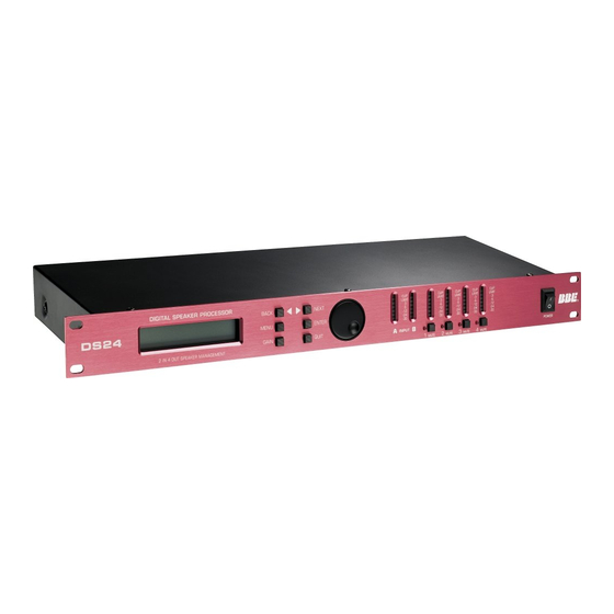
- Page 1 DIGITAL SPEAKER PROCESSOR DS24/DS26 •User Guide •Reference Manual professional products...
- Page 2 IMPORTANT SAFEGUARDS ®...
-
Page 3: Table Of Contents
CONTENTS DS24/DS26 and DS26 Features ……………………………………………………v 1 Introduction ……………………………………………………………………vi 2 What is a Speaker Management System? ……………………………………1 2.1 Crossover: ……………………………………………………………………1 2.2 Equalization: …………………………………………………………………1 2.3 Delay: ………………………………………………………………………1 2.4 High Pass and Low Pass Filters: …………………………………………1 2.5 Limiting: ………………………………………………………………………1 3 Front Panel ………………………………………………………………………2... - Page 4 If any of these items are found to be damaged or missing, immediately contact the BBE dealer you purchased it from. This manual will help you to effectively utilize the BBE DS24/26. Reviewing the information contained in this manual will answer most of the common questions that our service department...
-
Page 5: Ds24/Ds26 And Ds26 Features
• Choice of 2 X2-way, 2 X 3-way, 2-way + sub, 4-way, 5-way 6-way Crossovers crossover (depending on model) Parametric • DS24 is 2 inputs 4 outputs and includes 4 crossover configurations Equalizers • DS26 is 2 inputs 6 outputs and includes 6 crossover configurations Driver •... -
Page 6: Introduction
INTRODUCTION ® Thank you for choosing the BBE DS24/DS26 Speaker Management System. This product will enable you to obtain the best possible performance from your loudspeaker system. You can also reduce the amount of outboard gear that is required to transport, set-up and operate as part of the sound system. -
Page 7: What Is A Speaker Management System
These functions include crossover, equalization, delay, limiting, high-pass and low-pass filtering as well as signal distribu- tion. Programs may be created, selected and edited with the DS24/DS26's front panel controls. However, to create new programs, it is best to use the included free PC software and configure the programs using the graphical user interface (GUI) and a Windows PC. -
Page 8: Front Panel
FRONT PANEL ® 1. LCD The 2x20 backlit LCD displays the program and programming choices of the unit. 2. <Back/Next> These buttons allow navigation for selection of sub-menus and some parameter values. 3. Menu This is one of two buttons that will access the front panel programming. This one is used primarily to select which program to call up, edit or save. -
Page 9: Rear Panel
Connect this to the serial port on a PC using the included cable or other standard DB-9 type cable. With the software installed, the PC can now monitor and program the DS24/DS26. 3. XLR Input These are balanced (Pin 2 Hot) XLR inputs that accept the signal from the (usually main) outputs of the mixer. -
Page 10: Quickstart
Before hooking up the system, make sure that all items are OFF, especially the power amps. Use high quality balanced XLR mic cables to make the connections. The feeds from the DS24/DS26 at "front of house" can also be sent through the audio snake returns to the amp stacks if used in a live setting. - Page 11 QUICK START Depending on the mode selected, other options will appear for this level of the menu, primarily concerned with input and output assignments. Some assignments are fixed with the crossover type selected. Only those assignments that can be selected will show on the display. Either the BACK/NEXT (2) buttons or the Parameter dial will work for stepping through the selections.
-
Page 12: Installation
6.1 RACK MOUNTING The DS24/DS26 fits into one standard 19” rack unit of space. Please allow at least an additional 4” depth for the connectors on the back panel. Though this device does not generate significant heat, be sure that there is enough air space around the unit for cool- ing. -
Page 13: Operation
2.The second method uses the included Graphical User Interface (GUI) software run on a Windows PC. The computer connects to the DS24/DS26 and gives a more global view of the parameters and the choices for set- tings. -
Page 14: Submenus
7.2.1.4 Store a Xover: Store all the configuration settings of a X-OVER. The DS24/DS26 will store up to 10 program configurations in user memory locations. (An unlimited number can be stored on a PC or other PC accessible memory.) Each of the 10 programs can have a name containing up to 16 letters and numbers. -
Page 15: Subsystem Submenu
OPERATION Press MENU, NEXT and ENTER. Then use the NEXT/BACK and ENTER buttons to adjust the Security Submenu. The various locking modes are as follows: 1.LOCK: Changes only: Parameters can be viewed, but cannot be adjusted. MUTE buttons are valid. 2.LOCK: Changes + View: Parameters cannot be viewed or adjusted. -
Page 16: Interface Submenu
1.RS232 baud rate and address code setting: Select 2400, 4800, 9600, 19200, 38400 baud rate according to different PC capabilities. 2.Remote ID NUM: Select 1~32. Use this function when multiple DS24/DS26 units are used. Master Control unit is set as 1; slave units are set with subsequent numbers. -
Page 17: 2Outputs
OPERATION 7.6.1.2 Outputs: Press NEXT again and the screen will display an Output (Op1 = Output 1). Set the desired input gain level. At this point you can use the BACK/NEXT buttons to step through each of the parameters for the currently selected output. Press the GAIN button again to go to the next Output and program all of its parameters. -
Page 18: Peq
OPERATION ® HiPass: frequency range 10Hz~16.0KHz LoPass: frequency range 35Hz~22.0KHz Use HPF and LPF together to define the frequency band for this channel of the crossover. 7.6.1.7 PEQ: Set the parameters for the five available bands of parametric EQ. Press the PARAM dial to toggle between the three parameters on the display. -
Page 19: Name Of Channel
The time should be chosen care- fully as the danger of dynamics distortion usually increases with shorter attack times. The attack time of the DS24/DS26 can be set within a range of 1 to 100 mil- liseconds. -
Page 20: Ds26 Block Diagram
BLOCK DIAGRAMS ® 7.7 DS26 BLOCK DIAGRAMS PEQS GAIN Delay GAIN MUTE OUTPUT 1 INPUT A HIGH PEQS Delay GAIN MUTE OUTPUT 2 PEQS GAIN Delay GAIN MUTE OUTPUT 3 INPUT B HIGH PEQS Delay GAIN MUTE OUTPUT 4 Msub PEQS Delay GAIN... - Page 21 BLOCK DIAGRAMS PEQS GAIN Delay GAIN MUTE MUTE OUTPUT 1 INPUT A HIGH PEQS Delay GAIN MUTE MUTE OUTPUT 2 PEQS Delay GAIN MUTE MUTE OUTPUT 3 HIGH PEQS Delay GAIN MUTE MUTE OUTPUT 4 GAIN INPUT B MSUB PEQS Delay GAIN MUTE...
-
Page 22: Ds24 Block Diagram
BLOCK DIAGRAMS ® 7.8 DS24 BLOCK DIAGRAMS PEQS Delay GAIN LIMITER CLIP MUTE GAIN OUTPUT 1 INPUT A HIGH PEQS LIMITER CLIP MUTE Delay GAIN OUTPUT 2 GAIN INPUT B PEQS Delay GAIN LIMITER CLIP MUTE OUTPUT 3 OUT 3 & 4: B... -
Page 23: Graphical User Interface (Gui)
GRAPHICAL USER INTERFACE (GUI) The BBE SYSOMAX software provides a graphical method of programming on a DS24 or DS26. It can also be used to make changes in real time, if adjustments are required, during live operation. Full metering and control of all settings available on the PC. -
Page 24: Starting Up Sysomax
7.When the installation is complete, eject the CD-ROM 8.3 STARTING UP SYSOMAX To create a preset program on a DS24 or DS26 unit , first connect it to the computer with the serial cable. If your computer only has USB ports, adapters are available from com- puter suppliers. -
Page 25: Crossover Types Ds24
3.Device ID assigns a number between 1 and 64 to the unit. 4.Select Unit Type selects whether the unit is a DS24 or a DS26. 5.Format selects the main crossover mode for the unit. There are four types available for the DS24 and six types available for the DS26. -
Page 26: Top Line Menu
Clicking Online opens a dialog box with three buttons. Click Just Connect. (If the baud rate is not set correctly, the screen of the DS24 or DS26 will show “Communication Error”.)The Read and Write to/from MCU are for instances where multiple units are linked together and one unit is a master controller. - Page 27 GRAPHICAL USER INTERFACE (GUI) desired and click OK. The dialog box will close and you will be returned to the main screen view. To rename a program that has already been named, click on a program location in the table, then click Rename. Enter the desired name in the text box and click OK. The dia- log box will close and you will be returned to the main screen view.
-
Page 28: Creating A Program
CREATING A PROGRAM ® Once the device type and crossover type have been selected, the main screen will show blocks for each programmable section. The term “pro- gram” as used here is equivalent to “preset” as used on other program- mable devices. -
Page 29: Out 1, Out 2, Etc
Incorrect settings or mis-wiring (sending lows to a HF driver for instance) can damage or destroy your equipment. BBE Sound is not liable for any direct or consequential damages caused by improper use of its equipment. - Page 30 CREATING A PROGRAM ® Use the sliders to select values for Frequency., Q and Gain (cut/boost). An additional check box for FLAT will bypass all value selections. At the bottom of the screen are forward and back arrows to step through the five PEQ’s. Gain must be set to 0 (zero) to select a different type of filter including the Hi or Low Shelf filter.
-
Page 31: Specifications
SPECIFICATIONS BALANCED INPUTS Input Impedance ………………10KOhms CMRR …………………………50dB (30Hz~20KHz) As standard, the DS24/DS26 Output Impedance ……………<50Ohms Maxim output electrical level …Vpp=4V, Vpp=7.6V comes with electronically Frequency Resp ………………20Hz~20.0KHz servo-balanced inputs. This cir- Dynamic Range ………………110dB (A weighted) cuit design features automatic Distortion ………………………0.01%(THD) -
Page 32: Service
® 11 SERVICE We recommend that if at all possible, a BBE DS24 or DS26 that requires service be sent to our facility in Huntington Beach, California. We request that a “RETURN AUTHORIZA- TION” be issued by the dealer from whom you purchased the unit. If this is not possible, call BBE Sound, Inc. -
Page 33: Maintenance
All non-warranty repairs are warranted for a period of 90 days from the date of service. BBE Sound, Inc. is NOT LIABLE FOR CONSEQUENTIAL DAMAGES. Should the unit fail to operate for any reason, our sole obligation is to repair it as described above. - Page 34 ® 5381 Production Drive Huntington Beach, CA 92649 714-897-6766 • FAX 714-896-0736 www.bbesound.com BBE is the registered trademark of BBE Sound, Inc. rev. 1 5/2005...