Table of Contents
Advertisement
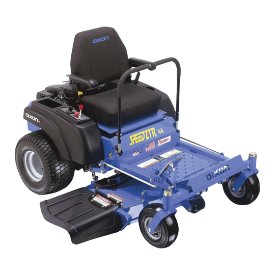
SPEEDZTR
Operator's Manual
SPEEDZTR 44 / 968999538
SPEEDZTR 36 / 968999539
SPEEDZTR 44 / 968999547
SPEEDZTR 36 / 968999609
SPEEDZTR 44 / 968999611
SPEEDZTR 42 / 968999689
SPEEDZTR 42 / 968999713
English
Please read the operator's manual carefully and make sure you
understand the instructions before using the machine.
Advertisement
Table of Contents

Related Manuals for Dixon 36 / 968999609


Summary of Contents for Dixon 36 / 968999609
- Page 1 SPEEDZTR Operator’s Manual SPEEDZTR 44 / 968999538 SPEEDZTR 36 / 968999539 SPEEDZTR 44 / 968999547 SPEEDZTR 36 / 968999609 SPEEDZTR 44 / 968999611 SPEEDZTR 42 / 968999689 SPEEDZTR 42 / 968999713 English Please read the operator’s manual carefully and make sure you...
-
Page 3: Table Of Contents
General ... 4 Driving and Transport on Public Roads ... 4 Towing ... 4 Operating ... 4 Safety Instructions ... 8 General Operation ... 8 Personal Safety Equipment ... 10 Slope Operation ... 10 Maintenance ... 12 General Maintenance ... 13 Transport ... -
Page 4: General
INTRODUCTION Congratulations Thank you for purchasing a Dixon ride-on mower. This machine is built for superior efficiency to rapidly mow primarily large areas. A control panel easily accessible to the operator and a hydrostatic transmission regulated by steering controls both contribute to the machine’s performance. -
Page 5: Good Service
Good Service Husqvarna’s products are sold all over the world and only in specialized retail stores with complete service. This ensures that you as a customer receive only the best support and service. Before the product is delivered, the machine has, for example, been inspected and adjusted by your retailer. See the certificate in the Service Journal in this operator’s manual. -
Page 6: Symbols And Decals
These symbols are found on the machine and in the operator’s manual. Study them carefully so that you know what they mean. WARNING! Xxxx xxxxxx xxxxx xxxx xxxxxxxxx xxxxxx xxxxxxxxx. xx xxxxxxxx xxxx xxxxxx. Used in this publication to notify the reader of a risk of personal injury or death, particularly if the reader should neglect to follow instructions given in the manual. - Page 7 SYMBOLS AND DECALS Read Shut off engine and Operator’s remove key before Manual performing any maintenance or repair work Whole body Severing of fingers exposure to and toes thrown objects Moving sharp blades under cover Keep a safe Use on slopes distance from no greater the machine...
-
Page 8: Safety Instructions
Safety Instructions These instructions are for your safety. Read them carefully. WARNING! This symbol means that important safety instructions need to be emphasized. It concerns your safety. IMPORTANT: THIS CUTTING MACHINE IS CAPABLE OF AMPUTATING HANDS AND FEET AND THROWING OBJECTS. - Page 9 • Never leave a running machine unattended. Always turn off blades, set parking brake, stop engine, and remove keys before dismounting. • Disengage blades when not mowing. Shut off engine and wait for all parts to come to a complete stop before cleaning the machine, removing the grass catcher, or unclogging the discharge guard.
-
Page 10: Personal Safety Equipment
Personal Safety Equipment WARNING! When using the machine, approved personal protective equipment (shown in illustrations) shall be used. Personal protective equipment cannot eliminate the risk of injury but it will reduce the degree of injury if an accident does happen. Ask your retailer for help in choosing the right equipment. - Page 11 grass catchers or other attachments; they can affect the stability of the machine. Do not use on steep slopes. • Do not try to stabilize the machine by putting your foot on the ground. • Do not mow near drop-offs, ditches, or embankments.
-
Page 12: Maintenance
Maintenance WARNING! The engine must not be started when the driver’s floor plate or any protective plate for the mower deck’s drive belt is removed. Safe Handling of Gasoline To avoid personal injury or property damage, use extreme care in handling gasoline. Gasoline is extremely flammable and the vapors are explosive. -
Page 13: General Maintenance
General Maintenance • Never operate machine in a closed area. • Keep all nuts and bolts tight to be sure the equipment is in safe working condition. • Never tamper with safety devices. Check their proper operation regularly. • Keep machine free of grass, leaves, or other debris buildup. - Page 14 • Ensure that nuts and bolts, especially the fastening bolts for the blade attachments, are properly tightened, torqued and that the equipment is in good condition. • Do not modify safety equipment. Check regularly to be sure it works properly. The machine must not be driven with defective or unmounted protective plates, protective cowlings, safety switches, or other protective...
-
Page 15: Transport
• The blades are sharp and can cause cuts and gashes. Wrap the blades or use protective gloves when handling them. • Check the parking brake’s functionality regularly. Adjust and service as necessary. • The mulch blades should only be used in familiar areas when higher quality mowing is desired. -
Page 16: Customer Responsibilities
• Follow the instructions under “Maintenance” and “Storage” sections of this owner’s manual. A spark arrester for the muffler is available through your authorized Dixon dealer. English SAFETY WARNING! This mower is equipped with an internal combustion engine and... -
Page 17: Controls
Controls This operator’s manual describes the Dixon Zero Turn Rider. The rider is fitted with either a Briggs & Stratton or Kohler four-stroke overhead valve engine developing 16 - 22 horse power. Transmission from the engine is made via two belt- driven hydraulic pumps, which in turn drive a hydraulic motor for each drive wheel. -
Page 18: Motion Control Levers
Recommended air pressure is 15 psi (1 bar). Tracking must be checked on a flat and level concrete or blacktop surface. If unit still does not track straight, contact a Dixon dealer for adjustment. English... -
Page 19: Seat Adjustment Lever
2. Seat adjustment lever The seat can be adjusted lengthways. When making adjustments, sit on the seat. Slide the lever to the side and maneuver seat to appropriate placement and release lever. 3. Unlocking Transmission When pushing or pulling the mower, be sure to engage the IZT (Integrated Zeroturn Transaxle) bypass linkages. -
Page 20: Refueling
4. Refueling The machine has one fuel tank, just behind the seat. The tank capacity is 4.5 gallons (17 liters). The engine will run on a minimum of 85-octane unleaded gasoline (no oil mix). Environmentally adapted alkylate gasoline can be used. See also Technical Data concerning ethanol fuel. -
Page 21: Ignition Switch
5. Ignition Switch The ignition key is placed on the driver’s panel and is used to start and stop the engine. IMPORTANT INFORMATION Do not run the starter for more than five seconds each time. If the engine does not start, wait about 10 seconds before retrying. -
Page 22: Blade Switch
8. Blade switch In order to engage the mower deck, pull the knob out; the mower blades are disengaged when the knob is depressed. 9. Circuit breaker The circuit breaker provides protection for the electrical system by (1) 15 amp circuit breaker. If the circuit breaker trips, push the button to reset. -
Page 23: Mower Deck Lift Lever
11. Mower Deck Cut Height Lift Lever Located to the right and front of the operator, the lift lever controls the cutting height. The deck cutting height is obtained by pressing the foot pedal forward to lift the deck. To lower the deck, apply pressure to the top side of the foot pedal and allow it to pivot while depressing the trigger and moving the lever forward. -
Page 24: Operation
Operation Read “Safety Instructions” section and following pages, if you are unfamiliar with the machine. Training Zero turn mowers are far more maneuverable than typical riding mowers due to their unique steering capabilities. We suggest that this section be reviewed in its entirety prior to attempting to move the mower under its own power. Additionally, we suggest when first operating the mower, use a reduced throttle speed and reduced ground speed by NOT moving control levers to the furthest forward or reverse positions during initial operation, or until operator becomes comfortable with controls. -
Page 25: Before Starting
Before Starting • Read the sections Safety Instructions and Controls before starting the machine. • Perform the daily maintenance before starting (see Maintenance Schedule in the Maintenance section). • Check that there is sufficient fuel in the fuel tank. • Adjust the seat to the desired position. - Page 26 • Move the steering controls outward to the locked (outer) neutral position. • Move the throttle to the middle position. • If the engine is cold, the throttle control should be pushed forward to its choke position. • Press in and turn the ignition key to the start position.
- Page 27 • When the engine starts, immediately release the ignition key back to the run position. IMPORTANT INFORMATION Do not run the starter for more than 5 seconds each time. If the engine does not start, wait about 10 seconds before retrying.
-
Page 28: To Start An Engine With A Weak Battery
To start an engine with a weak battery WARNING! Lead-acid batteries generate explosive gases. Keep sparks, flame and smoking materials away from batteries. Always wear eye protection when around batteries. If your battery is too weak to start the engine, it should be recharged. -
Page 29: Running
Running 1. Release the parking brake by moving the lever downward. Your mower is equipped with an operator presence system. When the engine is running, any attempt by the operator to leave the seat without first setting the parking brake will shut off the engine. -
Page 30: Operating On Hills
In order, for example, to turn right while moving forward, move the right control towards the neutral position. The rotation of the right wheel is reduced and the machine turns to the right. Turning on the spot can be achieved by moving one control backward (behind the neutral position) and carefully moving the other steering control forward from its neutral... -
Page 31: Mowing Tips
Mowing Tips • Observe and flag rocks and other fixed objects to avoid collisions. • Begin with a high cutting height and reduce it until the desired mowing result is attained. The average lawn should be cut to 2½" (64 mm) during the cool season and over 3"... -
Page 32: Stopping The Engine
Stopping the Engine Allow the engine to idle a minute in order to attain normal operating temperature before stopping it, if it has been worked hard. Avoid idling the engine for longer periods, as there is a risk of the spark plugs fouling. -
Page 33: Moving By Hand
Moving by Hand WARNING! Make no adjustments without: ♦ ♦ ♦ ♦ ♦ the engine stopped ♦ ♦ ♦ ♦ ♦ the ignition key removed ♦ ♦ ♦ ♦ ♦ the parking brake activated Unlocking Transmission When pushing or pulling the mower, be sure to engage the IZT (Integrated Zeroturn Transaxle) bypass linkages. -
Page 34: Maintenance Schedule
Maintenance Schedule The following is a list of maintenance procedures that must be performed on the machine. For those points not described in this manual, visit an authorized service workshop. An annual service carried out by an authorized service workshop is recommended to maintain your machine in the best possible condition and to ensure safe operation. - Page 35 Maintenance Check/adjust throttle cable Check the condition of belts, belt pulleys, etc. Change the engine oil Replace the engine oil filter Clean/replace the spark plugs Replace the air filter (paper filter) Check the caster wheels (every 200 hours) Clean the cooling fins Replace the air cleaner’s pre-filter Check/adjust the mower deck Check the engine valve clearance...
-
Page 36: Battery
Battery Your mower is equipped with a maintenance free battery and does not need servicing. However, periodic charging of the battery with an automotive type battery charger will extend its life. • Keep battery and terminals clean. • Keep battery bolts tight. •... -
Page 37: Ignition System
Ignition System The engine is equipped with an electronic ignition system. Only the spark plug requires maintenance. For recommended spark plug, see Technical Data. 1. Remove the ignition cable boot and clean around the spark plug. 2. Remove the spark plug with a spark plug socket wrench. - Page 38 Checking the Engine’s Cooling Air Intake Check that the engine’s cooling air intake is free from leaves, grass, and dirt. If the cooling air intake is clogged, engine cooling deteriorates, which can lead to engine damage. Checking and Adjusting the Throttle Cable Check that the engine responds to throttle increases and that a good engine speed is attained at full throttle.
- Page 39 Replacing the Air Filter If the engine seems weak or runs unevenly, the air filter may be clogged. If run with a dirty air filter, the spark plugs can become fouled, disrupting operation. For this reason, it is important to replace the air filter regularly (see the heading Maintenance Schedule for the proper service interval).
-
Page 40: Replacing The Fuel Filter
IMPORTANT INFORMATION! Do not use compressed air to clean the air filter. Do not wash the paper filter. Do not oil the paper filter. 4. Tap the paper filter against a fixed surface to remove dust. If the paper filter is still dirty, it must be replaced. -
Page 41: Checking Tire Pressures
Visually check that no damage is found on the lever, linages, or switch belonging to the parking brake. Perform a stand still test and check that there is a braking action. To adjust the parking brake, contact the Dixon service workshop. WARNING! Faulty adjustment can cause an accident. -
Page 42: Deck Belt Installation
Deck belt removal 1. Park on a level surface. Apply parking brake. 2. Lower the deck into the lowest cutting position. 3. Remove bolts from belt shields and remove shields. 4. Remove any dirt or grass that may have accumulated around the cutter housings and entire deck surface. -
Page 43: Pump Belt
Pump Belt To replace EZT (E-Series Zeroturn Transaxle) belt Park the mower on a level surface. Engage the parking brake. EZT belt removal NOTE: Be careful not to damage the fan blades on the EZT´s as this can affect cooling or damage the EZT´s •... - Page 44 Blade replacement WARNING! Blades are sharp. Protect your hands with gloves and/or wrap blades with a heavy cloth when handling. • Remove blade bolt by turning counterclockwise. • Install new or re-sharpened blade with stamped “GRASS SIDE” facing towards ground/grass (down) or “THIS SIDE UP” facing deck and cutter housing.
-
Page 45: Adjusting The Mower Deck
Adjusting the Mower Deck WARNING! Before performing any service or adjustment, check the following list: 1. Engage the parking brake. 2. Place the blade switch in the disengaged position. 3. Turn ignition switch to “OFF” position and remove the key. 4. -
Page 46: To Adjust Anti-Scalp Rollers
To adjust anti-scalp rollers Deck has anti-scalp rollers. Anti-scalp rollers are properly adjusted when they are just slightly off of the ground when the deck is at the desired cutting height in the operating position. Anti- scalp rollers then keep the deck in the proper position to help prevent scalping in most terrain conditions. -
Page 47: Parking Brake
Caster Wheels Check every 200 hours. Lift front of unit off of ground so caster wheels can rotate freely. Tighten caster bolt then back off ½ turn. Check that wheel rotates freely. If wheel does not rotate freely back the caster bolt off in ¼... -
Page 48: Tracking Adjustment
MAINTENANCE Tracking adjustment If the mower is not tracking straight, check the air pressure in both rear tires. Recommended air pressure is 15 psi (1 bar). If the unit will not track straight, follow the steps below. Tracking must be checked on a flat and level concrete or blacktop surface. -
Page 49: Lubrication Schedule
Lubrication Lubrication Schedule 12/12 Every year Lubricate with grease gun 1/52 Every Week 1/365 Every day *Change transaxles (transmission) filters. General Remove the ignition key to prevent unintentional movements during lubrication. When lubricating with an oil can, it must be filled with engine oil. When lubricating with grease, unless otherwise stated, use a high grade molybdenum disulfide grease. -
Page 50: Front Wheel Bearings
Lubricating the Cables If possible, grease both ends of the cables and move the controls to end stop positions when lubricating. Refit the rubber covers on the cables after lubrication. Cables with sheaths will bind if they are not lubricated regularly. If a cable binds, it can disrupt operation. -
Page 51: Deck Outer Spindle
Deck outer spindle Lubricate using a grease gun, one zerk, each side 2- 3 strokes. Use only good quality bearing grease. Engine Oil Changing the Engine Oil The engine oil should be changed for the first time after 5-8 hours of operation. Thereafter, it should be changed every 50 hours. -
Page 52: Checking The Oil Level
LUBRICATION Checking the Oil Level Check the oil level in the engine when the machine is standing level and the engine is stopped. Remove the dipstick, wipe it clean, and then replace it. The dipstick should be screwed into place. Take the dipstick out again and read the oil level. -
Page 53: Changing The Engine Oil Filter
Changing the Engine Oil Filter Drain the engine oil in accordance with the work description under the heading Engine Oil/ Change Engine Oil. Remove the oil filter. If necessary, use a filter remover. Wipe new, clean engine oil onto the seal for the new filter. - Page 54 Drain old oil filters of all free flowing oil prior to disposal. Place used oil in appropriate containers and dispose of it in accordance with laws in your area. Remove the top port plug (see illustration) from the left side and right side of the transaxles prior to filling with oil.
-
Page 55: Purging Procedures
Purging Procedures Due to the effects air has on efficiency in hydrostatic drive applications, it is critical that it is purged from the system. These purge procedures should be implemented any time a hydrostatic system has been opened to facilitate maintenance or any additional oil has been added to the system. -
Page 56: Trouble Shooting Guide
TROUBLE SHOOTING GUIDE Trouble Shooting Guide Problem The engine will not start. The starter does not turn the engine over. The engine runs rough. English Cause • The blade switch is engaged. • The steering controls are not locked in the neutral position. - Page 57 TROUBLE SHOOTING GUIDE The engine seems weak. The engine overheats. Battery not charging. The machine moves slowly, unevenly, or not at all. Mower deck not engaging. Transaxle leaks oil. • Clogged air filter. • Defective spark plugs. • Carburetor incorrectly adjusted. •...
- Page 58 TROUBLE SHOOTING GUIDE Uneven mowing results. The machine vibrates. English • Different air pressure in the tires on the left and right sides. • Bent blades. • The suspension for the mower deck is uneven. • The chain fixture has come loose. •...
-
Page 59: Storage
Service When ordering spare parts, please specify the purchase year, model, type, and serial number. Always use genuine Dixon spare parts. An annual check-up at an authorized service workshop is a good way to ensure that your machine performs its best the following season. -
Page 60: Wiring Diagram
WIRING DIAGRAMS Wiring diagram English... -
Page 61: Technical Data
Technical Data Engine Manufacturer Type Power Lubrication Oil capacity excl filter Oil capacity incl filter Engine oil, Synthetic Engine oil, Mineral Class Fuel Fuel tank capacity Spark plugs/gap Cooling Air filter Alternator Starter Transmission Transmission Speed and direction controls Speed forward Speed reverse Brakes Front caster tires, smooth tread... - Page 62 Equipment Cutting width Cutting height Uncut circle Number of blades Blade length Nose rollers Michigan Seat Hinged armrests Hour meter Blade engagement Deck construction Productivity Productivity Overall dimensions Weight Base machine length Base machine width Base machine height Overall width, chute up Overall width, chute down English TECHNICAL DATA...
- Page 63 Speed reverse Brakes Front caster tires, smooth tread Rear tires, Turf pneumatic Tire pressure, front and rear TECHNICAL DATA ZTR 36 / 968999609 Briggs & Stratton Intek 16 hp Pressure with oil filter 1.3 qt (1.31 liters) 1.5 qt (1.42 liters)
- Page 64 Weight Base machine length Base machine width Base machine height Overall width, chute up Overall width, chute down English TECHNICAL DATA ZTR 36 / 968999609 36" 1.5" - 4.5" 18.5" Standard Standard Electric clutch 11 gauge w/10 gauge skirts 2.55 acres / hr 538 lbs 70.5"...
- Page 65 Technical Data Engine Manufacturer Type Power Lubrication Oil capacity excl filter Oil capacity incl filter Engine oil, Synthetic Engine oil, Mineral Class Fuel Fuel tank capacity Spark plugs/gap Cooling Air filter Alternator Starter Transmission Transmission Speed and direction controls Speed forward Speed reverse Brakes Front caster tires, smooth tread...
- Page 66 Equipment Cutting width Cutting height Uncut circle Number of blades Blade length Nose rollers Michigan Seat Hinged armrests Hour meter Blade engagement Deck construction Productivity Productivity Overall dimensions Weight Base machine length Base machine width Base machine height Overall width, chute up Overall width, chute down English TECHNICAL DATA...
- Page 67 Technical Data Engine Manufacturer Type Power Lubrication Oil capacity excl filter Oil capacity incl filter Engine oil, Synthetic Engine oil, Mineral Class Fuel Fuel tank capacity Spark plugs/gap Cooling Air filter Alternator Starter Transmission Transmission Speed and direction controls Speed forward Speed reverse Brakes Front caster tires, smooth tread...
- Page 68 Equipment Cutting width Cutting height Uncut circle Number of blades Blade length Nose rollers American Craftsman Seat Hinged armrests Hour meter Blade engagement Deck construction Productivity Productivity Overall dimensions Weight Base machine length Base machine width Base machine height Overall width, chute up Overall width, chute down English TECHNICAL DATA...
-
Page 69: Torque Specifications
Accessories BioClip attachment (Mulch kit) Collection system Torque Specifications ·Engine crankshaft bolt ·Deck pulley bolts ·Lug nuts ·Blade bolt ·Standard ¼" fasteners ·Standard " fasteners ·Standard " fasteners ·Standard " fasteners ·Standard ½" fasteners When this product is worn out and no longer used, it should be returned to the reseller or other party for recycling. In order to implement improvements, specifications and designs can be altered without prior notification. -
Page 70: Conformity Certificates
CONFORMITY CERTIFICATES Conformity Certificates USA requirements Labels are placed on the engine and/or in the engine compartment stating that the machine will fulfill the requirements. This is also applicable to special requirements for any of the states, (California emission rules etc.). -
Page 71: Service Journal
Service Journal Action Delivery Service 1. Charge the battery. 2. Adjust the tire pressure of all wheels to 15 PSI (1 bar). 3. Mount the steering controls in the normal position. 4. Connect the contact box to the cable for the seat’s safety switch. - Page 72 SERVICE JOURNAL After the First 5-8 Hours 1. Change engine oil. English...
- Page 73 SERVICE JOURNAL Action Date, mtr reading, stamp, sign 25-Hour Service 1. Check the fuel pump’s air filter. 2. Sharpen/Replace mower blades if required. 3. Check the tire pressures. 4. Check battery with cables. 5. Lubricate according to lubrication chart. 6. Check/clean the engine’s cooling air intake. 7.
- Page 74 SERVICE JOURNAL Action Date, mtr reading, stamp, sign 50-Hour Service 1. Perform the 25-hour service. 2. Clean/replace the air cleaner’s filter cartridge (paper filter) (shorter intervals for dusty operating conditions). Change engine oil. 4. Lubricate according to lubrication chart. 5. Check/adjust the parking brake.
- Page 75 Action 100-Hour Service 1. Perform the 25-hour service. 2. Perform the 50-hour service. 3. Change the engine oil filter. 4. Clean/replace the spark plugs. 5. Replace the fuel filter. 6. Clean the cooling fins on the engine and transmission. Check V-belts. Check tighten caster wheel axle bolts (every 200 hours).
- Page 76 SERVICE JOURNAL Action Date, mtr reading, stamp, sign 300-Hour Service 1. Inspect the machine. Come to agreement with the customer as to which additional work is to be carried out. 2. Perform the 25-hour service. 3. Perform the 50-hour service. 4.
- Page 77 SERVICE JOURNAL Action Date, mtr reading, stamp, sign At Least Once Each Year 1. Clean the engine’s cooling air intake (25 hours). 2. Replace the air cleaner’s pre-filter (foam) (300 hours). 3. Replace the air filter’s paper cartridge. 4. Change the engine oil (50 hours). 5.
- Page 78 SERVICE JOURNAL Action Date, mtr reading, stamp, sign...
- Page 80 Part No. 539 131911 Rir (07/27/07)