Advertisement
Quick Links
SI 24TE
SI 37TE
Sole/Wasser-
Wärmepumpe für
Innenaufstellung
Bestell-Nr. / Order no. / N
Brine-to-Water
Heat Pump for
Indoor Installation
o
de commande : 452234.66.10
Montage- und
Gebrauchsanweisung
Installation and
Operating Instructions
Instructions d'installation
et d'utilisation
Pompe à chaleur
eau glycolée-eau
pour installation
intérieure
FD 8609
Advertisement
Chapters

Summary of Contents for Dimplex SI 24TE SI 37TE
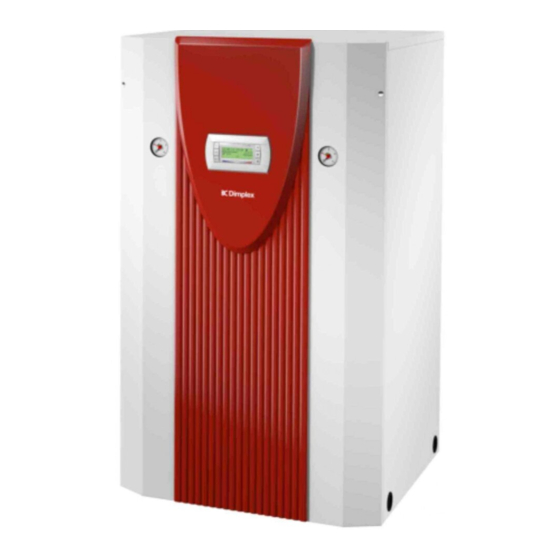
- Page 1 Wärmepumpe für Innenaufstellung Bestell-Nr. / Order no. / N de commande : 452234.66.10 Montage- und Gebrauchsanweisung Installation and Operating Instructions Instructions d’installation et d’utilisation Brine-to-Water Heat Pump for Indoor Installation Pompe à chaleur eau glycolée-eau pour installation intérieure FD 8609...
-
Page 2: Table Of Contents
Table of contents Read immediately...E-2 1.1 Important Information... E-2 1.2 Legal Provisions and Guidelines ... E-2 1.3 Energy-Efficient Use of the Heat Pump ... E-2 Purpose of the heat pump ...E-2 2.1 Application ... E-2 2.2 Principle of Operation ... E-2 Baseline Unit...E-3... -
Page 3: Read Immediately
Read immediately 1.1 Important Information ATTENTION! Any work on the heat pump may only be performed by an authorised and qualified customer service. ATTENTION! The heat pump must not be tilted more than max. 45° (in either direction). ATTENTION! The transport securing devices must be removed prior to commissioning. -
Page 4: Baseline Unit
ATTENTION! The heat pump must not be tilted more than max. 45° (in either direction). After the transport, the transport securing device is to be re- moved on either side at the bottom of the unit. -
Page 5: Installation
Provided the controller and heating circulating pumps are ready for operation, the frost protection feature of the controller is ac- tive. If the heat pump is taken out of service or in the event of a power failure, the system has to be drained. In heat pump instal-... -
Page 6: Commissioning
ATTENTION! The clockwise phase sequence must be observed when connecting the load lines (the heat pump will deliver no output and will be very noisy when the phase sequence is incorrect). The power cable must be run through the guide tubes, inserted into the side of the control box and secured by means of the strain relief. -
Page 7: Care/Cleaning
If you cannot correct the malfunction yourself, please contact the after-sales service agent in charge. ATTENTION! All work on the heat pump may only be performed by an authorised an qualified after-sales service. ATTENTION! Disconnect all electrical circuits from the power supply before opening the enclosure. -
Page 8: Equipment Data
3. Operation with 1 compressors 4. Note that additional space is required for pipe connections, operation and maintenance. 5. See CE declaration of conformity 6. The heat circulating pump and the heat pump controller must always be ready for operation. www.dimplex.de °C °C... - Page 9 3.4 Legende / Legend / Légende...A-IX Hydraulisches Prinzipschema / Hydraulic block diagrams / Schéma hydraulique ... A-X 4.1 Darstellung / Schematic view / Représentation schématique ...A-X 4.2 Legende / Legend / Légende...A-XI Konformitätserklärung / Declaration of Conformity / Déclaration de conformité ... A-XII www.dimplex.de...
-
Page 10: Maßbilder / Dimensioned Drawings / Schémas Cotés
1 Maßbilder / Dimensioned drawings / Schémas cotés 1.1 Maßbild / Dimensioned drawing / Schéma coté SI 24TE A-II... -
Page 11: Maßbild / Dimensioned Drawing / Schéma Coté Si 37Te
1.2 Maßbild / Dimensioned drawing / Schéma coté SI 37TE www.dimplex.de A-III... -
Page 12: Diagramme / Schematics / Diagrammes
2 Diagramme / Schematics / Diagrammes 2.1 Kennlinien / Schematics / Courbes caractéristiques SI 24TE A-IV... -
Page 13: Kennlinien / Schematics / Courbes Caractéristiques Si 37Te
2.2 Kennlinien / Schematics / Courbes caractéristiques SI 37TE www.dimplex.de... -
Page 14: Stromlaufpläne / Wiring Diagrams / Schémas Électriques
3 Stromlaufpläne / Wiring diagrams / Schémas électriques 3.1 Steuerung / Control / Commande A-VI... -
Page 15: Last / Load / Charge
3.2 Last / Load / Charge www.dimplex.de A-VII... -
Page 16: Anschlussplan / Terminal Diagram / Schéma De Branchement
3.3 Anschlussplan / Terminal diagram / Schéma de branchement A-VIII... -
Page 17: Legende / Legend / Légende
Zusätzlicher Sperreingang Mischer AUF Mischer ZU Bauteile sind bauseits beizustellen, bzw. als Zube- hör erhältlich www.dimplex.de Wire jumper, must be removed when an A2 utility blocking contactor is installed Wire jumper, must be removed if 2nd disable input is used... -
Page 18: Hydraulisches Prinzipschema / Hydraulic Block Diagrams / Schéma Hydraulique
4 Hydraulisches Prinzipschema / Hydraulic block diagrams / Schéma hydraulique 4.1 Darstellung / Schematic view / Représentation schématique... -
Page 19: Legende / Legend / Légende
Mischer 2. Heizkreis Regeleinheit Außenwandfühler Rücklauffühler Warmwasserfühler Fühler 2. Heizkreis Fühler 3. Heizkreis Elektroverteilung Kaltwasser Warmwasser www.dimplex.de Check valve Shutoff valve Three-way mixer Circulating pump Expansion vessel Shutoff valve with check valve Safety valve combination Heat consumer Temperature sensor Flexible connection hose... -
Page 20: Konformitätserklärung / Declaration Of Conformity / Déclaration De Conformité
5 Konformitätserklärung / Declaration of Conformity / Déclaration de conformité A-XII... - Page 21 Glen Dimplex Deutschland GmbH Irrtümer und Änderungen vorbehalten. Geschäftsbereich Dimplex Subject to alterations and errors. Am Goldenen Feld 18 Sous réserve d’erreurs et modifications. D-95326 Kulmbach +49 (0) 9221 709 565 www.dimplex.de...


