Dell PowerEdge R510 Technical Manual
A 2-socket, 2u high-capacity, multi-purpose rack server
Hide thumbs
Also See for PowerEdge R510:
- Hardware owner's manual (216 pages) ,
- Getting started (145 pages) ,
- Technical manualbook (73 pages)

Related Manuals for Dell PowerEdge R510


Summary of Contents for Dell PowerEdge R510
- Page 1 Dell Product Name Dell PowerEdge R510 Name Technical Guide Excellent balance of internal storage, redundancy, and value in a compact chassis...
- Page 2 InfiniBand Trade Association. Matrox is a registered trademark of Matrox Electronic Systems Ltd. Microsoft and SQL Server are either registered trademarks or trademarks of Microsoft Corporation in the United States and/or other countries. Mellanox is a registered trademark of Mellanox Technologies, Inc. and ConnectX, InfiniBlast, InfiniBridge, InfiniHost, InfiniRISC, InfiniScale, and InfiniPCI are trademarks of Mellanox Technologies, Inc.
-
Page 3: Table Of Contents
Security ... 33 4.11.1 Bezel Lock ... 33 4.11.2 Hard Drive Security ... 34 4.11.3 Intrusion Switch ... 34 4.11.4 Top Cover ... 34 4.12 USB Key ... 34 4.13 Battery ... 35 PowerEdge R510 Technical Guide Table of Contents... - Page 4 PCI Device Information ... 54 10.1.3 Boot Order for Riser 1 ... 54 10.1.4 PCI Card Dimensions ... 54 10.2 Riser 2 Detail ... 54 10.2.1 PCI Device information ... 55 10.2.2 Boot Order for Riser 2 ... 55 PowerEdge R510 Technical Guide...
- Page 5 Riser 2 Slot Information ... 55 Table 22. PCI Card Dimensions: Riser 2 ... 55 Table 23. Raid Configurations for the PowerEdge R510-4 ... 57 Table 24. Raid Configurations for the PowerEdge R510-8 ... 58 Table 25. RAID Configuration for PowerEdge R510-12 ... 60 Table 26.
- Page 6 PowerEdge R510-4: Non-Redundant PSU and the Battery Holder for PERC Card ... 26 Figure 15. Cabled HDD, No Backplane ... 26 Figure 16. PowerEdge R510-12 Internal View (Redundant PSU with PDB and Additional Fan for PSU) ... 27 Figure 17. PowerEdge R510–12 Internal View ... 27 Figure 18.
-
Page 7: Overview
The result is PowerEdge R510 solution uses up to 50 percent less power than the legacy HP ProLiant DL385 solution. - Page 8 Unified Server Configurator (USC) in a pre-OS environment. This helps eliminate the need to use and maintain multiple pieces of disparate CD/DVD media.
-
Page 9: Product Comparison
8 x 2.5‖ Hot-swap POWER SUPPLY Hot-swap, Redundant COOLING Hot-swap, Redundant 8 and 16 are not supported on the PowerEdge R510-4 due to power supply limitations. PowerEdge R510 Technical Guide Comparison of PowerEdge Server Features PowerEdge R710 (Current) Intel 5520 chipset... - Page 10 PowerEdge R510 Technical Guide PowerEdge R710 (Current) iDRAC 6 Express Optional iDRAC6 Enterprise and vFlash PowerEdge R510 (New) LED for PowerEdge R510-4 and R510-12 LCD for PowerEdge R510-8 BMC, IPMI 2.0 compliant Optional for iDRAC6 Express and iDRAC6 Enterprise and vFlash...
-
Page 11: New Technologies
Intel Turbo Boost, which boosts frequency for active cores by up to 400 MHz for during peak demand periods. 2.1.2 Intel 5500 Chipset Although the chipset supports up to 18 DIMMs, the PowerEdge R510 is designed with 8 DIMM slots. For more information on the Intel 5500 chipset, see Section 8, Sparing Intel has added sparing back with Xeon processor 5600 series. -
Page 12: Figure
The chart below shows the components of the new embedded server management capability. The PowerEdge R510 default server management is the Baseboard Management Controller (BMC). iDRAC6 Express and iDRAC6 Enterprise are offered as upgrade options. The iDRAC Express hosts the Lifecycle Controller and Unified Server Configurator. -
Page 13: System Overview
Dell 3 System Overview PowerEdge R510 provides a value 2S 2U server, with maximized storage capacity, high performance, simplified management, and an affordable price. PowerEdge R510–4 drives Chipset Intel® 5500 chipset (Intel 5500 chipset+ ICH10R) Intel® Xeon® processor 5500 and 5600 series... - Page 14 3.5"/15K 146GB 300GB 450GB 600GB 3.5"/10K 600GB PowerEdge R510 Technical Guide PowerEdge R510–8 drives 22.5 Kg /49.5 lbs 13.5 Kg/29.7 lbs 8 x 3.5" Hot-swap HDD 8 x 2.5" Hot-swap HDD Passive (w/o expander), support 8x 3.5"/7.2K (in hard drive carrier)
- Page 15 PERC 6/E PERC H200 (6Gb/s) PERC H700 (6Gb/s) PERC H800 (6Gb/s) SW RAID: PERC S100 PERC S300 PowerEdge R510 Technical Guide PowerEdge R510–8 drives 2.5" (in hard drive carrier through conversion kit) 25GB SATA SSD 50GB SATA SSD 100GB SATA SSD...
- Page 16 VMware® Virtual Infrastructure Version 3.5 Update 4 (Classic version is DIB; embedded version can be download from VMware website and installed on hard drive. Hypervisor is supported through USB key for PowerEdge R510-4, 8, and 12.) Citrix® XenServer™ Enterprise 5.5 HPCC: Microsoft®...
- Page 17 ReadyRails™ static rails for tool-less mounting in 4-post racks with square or unthreaded round holes or tooled mounting in 4-post threaded and 2-post (Telco) racks PowerEdge R510 Technical Guide PowerEdge R510–8 drives PowerEdge R510-12 drives...
-
Page 18: Mechanical
Dell 4 Mechanical 4.1 Chassis Description PowerEdge R510 chassis is a 2U rack system. The chassis is not swappable. Supported configurations are detailed in Table 3. Table 3. 4-HDD Configuration 5 x cabled 3.5‖ HDD bay Non-Redundant 480W PSU Quad pack diagnostic LED 4.2 Dimensions and Weight... -
Page 19: Figure
Dell System Dimensions Figure 3. PowerEdge R510 Technical Guide... -
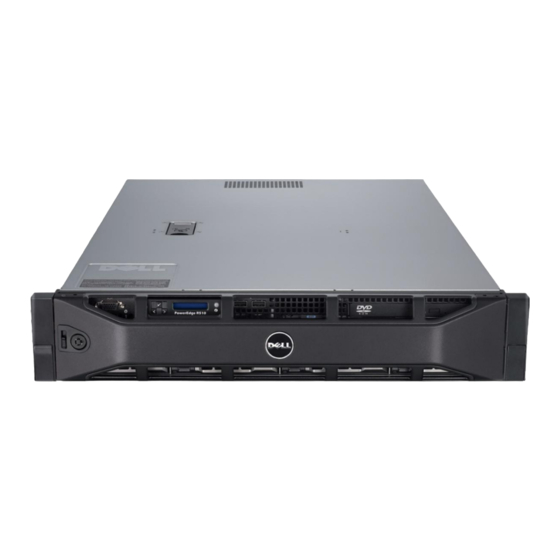
Page 20: Front Panel View And Features
Dell 4.3 Front Panel View and Features Figure 4. Figure 5. PowerEdge R510 Technical Guide PowerEdge R510–4 HDD Configuration PowerEdge R510–8 HDD Configuration... -
Page 21: Nmi Button
When the System ID buttons are pressed, the System Status/ID LED in the front and in the back blink, identifying the particular server in a rack full of servers. This button remains functional during non-operational (that is, standby and shutdown) modes. -
Page 22: Video Connector (Rack Systems)
All PowerEdge servers include a green colored LED on the motherboard to indicate the presence of standby power (Vaux). This LED is in a visible location for service personnel. Some server operating systems allow users to configure the function of the power button through the ACPI feature. -
Page 23: Dvd/Cd
4.3.7 Hard Drive Activity LED The PowerEdge R510 systems have a single (common) green hard drive activity LED that lights when the system is accessing data on the drive. These systems do not have Status LEDs. -
Page 24: Back Panel View And Features
R510 with Non-Redundant Power Supply for PowerEdge R510-4 ONLY Figure 9. Figure 10. With Redundant Power Supply for PowerEdge R510-8 and 12 Figure 11. Non-redundant Power Supply Option on PowerEdge R510-8 and 12 Only redundant Power Supply Units (PSUs) have a LED indicator to show the power supply status. -
Page 25: Side Views And Features
Replace the power supply that has the flashing indicator with a power supply that matches the capacity of the other installed power supply. 4.5 Side Views and Features PowerEdge R510 Technical Guide Figure 12. Redundant PSU Figure 13. Left Side View... -
Page 26: Internal Chassis Views
Dell 4.6 Internal Chassis Views Battery Holder Figure 15. PowerEdge R510-4: Non-Redundant PSU and the Battery Holder for PERC Card Figure 16. Cabled HDD, No Backplane PowerEdge R510 Technical Guide... -
Page 27: Figure
Dell Figure 17. PowerEdge R510-12 Internal View (Redundant PSU with PDB and Additional Fan for PSU) Figure 18. PowerEdge R510–12 Internal View PowerEdge R510 Technical Guide... -
Page 28: Rails And Cable Management
ReadyRails Static Rails for 4-post & 2-post Racks dimensions: Rail depth: 622 mm Square-hole rack adjustment range: 608-879 mm Round-hole rack adjustment range: 594-872 mm Threaded-hole rack adjustment range: 604-890 mm PowerEdge R510 Technical Guide party... -
Page 29: Rail View
Dell 4.8 Rail View Figure 19. R510 Sliding Rails without CMA Figure 20. R510 Sliding Rails with CMA PowerEdge R510 Technical Guide... -
Page 30: Fans
Dell Figure 21. R510 Static Rails Figure 22. R510 Static Rails in Rack 4.9 Fans 4.9.1 Fan module PowerEdge R510-4 and PowerEdge R510-8 have the same fan module. PowerEdge R510 Technical Guide... -
Page 31: Fan Location And Installation
4.9.2 Fan Location and Installation PowerEdge R510-4 has four fan modules (it does not have the fan circled in red as shown in Figure 25). PowerEdge R510-8 has five fan modules. PowerEdge R510-12 has five redundant fan modules which contain 2 fans each for a total of 10 fans. -
Page 32: Fan Connector And Connector Locations
Dell Figure 25. Fan Location 4.9.3 Fan Connector and Connector Locations Figure 26. Fan Connector Locations PowerEdge R510 Technical Guide... -
Page 33: Cabling
4.11.1 Bezel Lock The bezel lock located on front of the bezel provides security for the system by preventing access to hard drives, optical drives, and the power button. PowerEdge R510 Technical Guide Cabling Information Table 8. Controller No Add-in RAID controller... -
Page 34: Hard Drive Security
The top cover latch has a coin lock. 4.12 USB Key The PowerEdge R510-4 and 8 support 2 internal USB connectors that can be used for USB keys, located at the front control board as shown in the following two figures (circled in red). -
Page 35: Battery
Dell The PowerEdge R510-12 internal USB connectors are on the backplane as shown below. Figure 29. PowerEdge R510–12 USB Connector 4.13 Battery A replaceable lithium battery (CR2032) is mounted on the motherboard to provide backup power for the Real-Time Clock in the ICH10R and CMOS RAM on the Super I/O controller. -
Page 36: Power, Thermal, Acoustic
1100W power supply. A hot-plug redundant 750W option is available for the 8- and 12-HDD configurations. Power is soft-switched, allowing power cycling using a switch on the front of the system enclosure or using software control (through server management functions). The power system is compatible with industry standards, such as ACPI and Server 2000. -
Page 37: Thermal
Optimized thermal management makes PowerEdge R510 cool and quiet. Benefiting from a smart cooling thermal control algorithm, the PowerEdge R510 can keep both high performance and good acoustics across a wide range of ambient temperatures (10 °C – 35 °C). In addition, the PowerEdge R510 provides cooling efficiency that saves energy. -
Page 38: Maximum Input Amps
Redundant power supply: 10.8 - 5 A at 100-240 VAC, 50/60 Hz 5.5 Energy Star Compliance See the ENERGY STAR Compliance results PowerEdge R510 Technical Guide Operating/Non-Operating (Storage) Requirements Operating Requirements 10 to 35 °C (50 to 95 °F) 10 to Note °C... -
Page 39: Acoustics
Dell 5.6 Acoustics The acoustical design of the PowerEdge R510 reflects the following: Adherence to Dell’s high sound quality standards. Sound quality is different from sound power level and sound pressure level in that it describes how humans respond to annoyances in sound, like whistles, hums, etc. -
Page 40: Table 10. Acoustics Of 4-Hdd Chassis
Max. Configurations @ 12 x 600GB Hot- plug SAS (3.5‖/ 2 x Intel 15k RPM) X5570/2.80 2 x 300GB SAS (2.5‖/ 10K) PowerEdge R510 Technical Guide Acoustics of 4-HDD Chassis Table 10. °C 23 ± 2 Operating Mode RAID DIMM... - Page 41 The system is placed in a rack with its bottom at 75 cm from the floor. The acoustic transducer is at front bystander position, ref ISO7779 (1999) Section 8.6.2. PowerEdge R510 Technical Guide The system is placed in a rack with its bottom at 75 cm from the floor. The acoustic...
-
Page 42: Processors
Dell 6 Processors R510 can operate in either single-processor or dual-processor mode. However, since the memory controller is embedded in the processor, when only one processor is installed in the system, it supports 4 DIMMs, with minimum memory of 1GB and maximum memory of 64GB (based on the 16GB module). When two processors are installed in the system, it supports 8 DIMMs, min. -
Page 43: Memory
Intel has added sparing back with Xeon processor 5600 series. In sparing mode, you must have identical memory in Channel_0, Channel_1 and Channel_2. For the R510, memories are installed in A1, A2 and A3 to enable the sparing mode. With sparing mode is enabled, usable memory capacity is 2/3 of the physical memory installed. -
Page 44: Chipset
5500 chipset, which is required to enable the full 5600 series feature set. Dell servers shipped with the new chipset revision have the symbol II in the System Revision Field visible through OpenManage™ Server Administrator (OMSA) and the iDRAC GUI. They are physically marked with a 12 x 6mm rectangular label containing the symbol II. -
Page 45: Pci Express* Interfaces
The ESI interface connects the Intel 5500 chipset MCH to the ICH10R. The ESI interface runs at 2 GB/s with a 100 MHz reference clock. 8.3 Intel ICH10R South Bridge The PowerEdge R510 planar incorporates the Intel ICH10R chip. The ICH10R is a highly integrated I/O controller. 8.3.1 DMI interface The DMI interface connects the ICH10R to the IOH. -
Page 46: Bios
This permits the BIOS to be upgraded in the field via a bootable device rather than by physically removing an EEPROM. The System BIOS, Video BIOS, server management, and PCI configuration are housed in this flash. The following table clarifies what is and is not supported by the PowerEdge R510 BIOS code. Supported System BIOS... -
Page 47: Acpi
Generic features have defined enable and status bits, but the functionality is not fully visible to the OS. Dell provides ASL code to handle the details of generic features, allowing the OS to intelligently communicate with system-specific hardware. PowerEdge R510 Technical Guide... -
Page 48: Table 15. Summary Of Power Management Features
Power Profile support Current Power Profiles that 11G BIOS exposes in BIOS setup are detailed in the following table. The Active Power Controller mode is the default mode. PowerEdge R510 Technical Guide Summary of Power Management Features Enable/Status/ Ctrl Description... -
Page 49: Table 16. Supported Power Profiles
Performance | Power Table 17 details power management state transitions. Table 17. Wake Up Events Power Button PME# MOUSE PowerEdge R510 Technical Guide Supported Power Profiles Table 16. Power Management State Transition States Can Wake From OS-S4* Not supported Not supported... -
Page 50: Uefi And Acpi
Dell 9.3 UEFI and ACPI For PowerEdge R510 systems, the UEFI layer does not participate in generation of the ACPI (Advanced Configuration and Power Interface) table. The ACPI table is generated by the BIOS and UEFI exposes the ACPI table as an EFI configuration table entry. See the UEFI 2.1 specification for the details on EFI configuration table and the ACPI_TABLE_GUID. -
Page 51: Uefi
OS (UEFI compatible) and the UEFI pre-boot applications. The PowerEdge R510 implementation is compliant with UEFI version 2.1. Interfaces are implemented in 64-bit processor mode. PowerEdge R510 runs UEFI over legacy BIOS. The system BIOS executes, initializing the system and configuring the hardware. -
Page 52: Table 19. Uefi Summary
Independent of processor and chipset technology. Running in 64-bit long mode Supportive of GUID Partition Table (GPT) formatted disks PowerEdge R510 Technical Guide UEFI Summary Table 19. A PIWG (DXE, PEI) implementation A complete rewrite of the system firmware ... -
Page 53: O Slots
Dell 10 I/O Slots 10.1 Overview The PowerEdge R510 system provides two configurations for I/O slots: Riser 1 (default offering): Three PCIe slots (x4, x4, x8 bandwidth; all w/ x8 slots) + One internal storage slot (x4 bandwidth w/ x8 slot for SAS or PERC integrated cards only) ... -
Page 54: Pci Device Information
PCIe x8 Slot4 (Gen2) PCIe x4 10.2 Riser 2 Detail (Offered via customer upgrade kit, as this card is dedicated for external GPGPU solution only.) PowerEdge R510 Technical Guide PCI Card Dimensions: Riser 1 Table 21. Physical Slot PCIe x8... -
Page 55: Pci Device Information
System supports 25W maximum power for the slot 1 and 15W for slot 2 The lower power support on slot 2 is due to system thermal limitations instead of system power • requirements The PowerEdge R510 does not support hot-swapping of PCIe cards • 10.2.1 PCI Device information IOH port 1, 2 (PCI Express Gen2 x4) –... -
Page 56: Storage
Dell 11 Storage 11.1 Overview There are two types of chassis for R510. • 4 Hard Drive Chassis: x cabled 3.5‖ HDD (cabled HDD carrier, identical to R410 cabled HDD carrier), support one slim optical disk drive (ODD) • 8 Hard Drive Chassis: 8 x hot-swap 3.5‖ or 2.5‖ HDD (in hard drive carrier), support one slim ODD 11.2 Drives... -
Page 57: Raid Configurations
ASSR1CBL card) ASSR10CBL ASSR5CBL ASSR1/R1CBL PowerEdge R510 Technical Guide Raid Configurations for the PowerEdge R510-4 Description No controller/No Hard Drive No RAID (ICH) RAID0 for 2 HDDs (PERC S100) RAID0 for 3 and above HDDs (PERC S100) RAID1 (PERC S100) -
Page 58: Table 25. Raid Configurations For The Poweredge R510-8
ASSR60 ASSR1/R1 ASSR1/R5 ASSR5/R10 PowerEdge R510 Technical Guide Raid Configurations for the PowerEdge R510-8 Description No Hard Drive (controller required, PERC S300, SAS 6/iR, PERC H200, PERC 6/i, PERC H700) RAID0 for 2 HDDs (PERC S300) RAID0 for 3 and above HDDs (PERC S300) - Page 59 Dell R510-8 Mixed HDD (SAS + SATA) Factory Configuration Type Name ASS-X (Add- ASSR1/R1-X card) ASSR1/R5-X ASSR5/R10-X R510-8 Mixed HDD (SSD + SAS) Factory Configuration Type Name ASS-X (Add- ASSR1/R1-X card) ASSR1/R5-X ASSR5/R10-X PowerEdge R510 Technical Guide Description No RAID (SAS 6/iR, PERC H200)
-
Page 60: Table 26. Raid Configuration For Poweredge R510-12
Type Name (Add- card) ASS-X PowerEdge R510 Technical Guide RAID Configuration for PowerEdge R510-12 Description No Hard Drive (controller required, PERC H200, PERC H700) No RAID (PERC H200) RAID0 (PERC H200, PERC H700) RAID1 (PERC H200, PERC H700) RAID10 (PERC H200, PERC H700) - Page 61 Dell ASSR1/R1-X ASSR1/R5-X ASSR5/R10-X R510-12 Mixed HDD (SSD + SAS) Factory Configuration Type Name (Add- card) ASS-X ASSR1/R1-X ASSR1/R5-X ASSR5/R10-X R510-12+2 Factory Configurations Type Name (recommende d for hidden)iR1 RAID (Add- card) ASS/+iR1 RAID (Add- card) ASSR0/+iR1 ASSR1/+iR1 ASSR10/+iR1 ASSR5/+iR1...
- Page 62 Name Mix HDD (Add-in card) ASS-X/+iR1 ASSR1/R1-X/+iR1 ASSR1/R5-X/+iR1 ASSR5/R10- X/+iR1 PowerEdge R510 Technical Guide RAID50 (PERC H700) RAID60 (PERC H700) RAID1+RAID1 (PERC H200, PERC H700) RAID1 + RAID5 (PERC H700) RAID5 + RAID10 (PERC H700) Description No RAID (PERC H200)
-
Page 63: Optical Drives
Dell 11.4 Optical Drives R510 supports a SATA interface slim DVD-ROM or slim DVD+/-RW. Slim ODD option is available on 4-HDD and 8-HDD configuration chassis only. R510-12 does not support internal ODD; external USB ODD options are available. 11.5 Tape Drives R510 does not support an internal backup device. -
Page 64: Video
1024x768 (60/72/75/85 Hz; 8/16/32-bit color) • 1152x864 (75 Hz; 8/16/32-bit color) • 1280x1024 (60/75/85 Hz; 8/16-bit color) • 1280x1024 (60 Hz, 32-bit color) (note 32 bit color is only supported at 60 Hz for this resolution) PowerEdge R510 Technical Guide... -
Page 65: Operating Systems
Hyper-V Server (V-SKU) Windows Server 2003 R2 x64 (with Windows Server 2008 hyper-v role enabled) Windows Server 2008 SP2 PowerEdge R510 Technical Guide Operating System Support Matrix for Dell PowerEdge Systems Microsoft Operating Systems Supported Installation Factory Install Standard Premium... - Page 66 Standard (2-sckt) x86-64 Red Hat Enterprise Linux HPC (2-sckt) x86-64 Standard (2-sckt) x86-32 SLES10 SP2 x86-64 SLES10 SP3 X86-64 SLES 11 x86-64 PowerEdge R510 Technical Guide Standard Enterprise Datacenter HPC Server 2008 Linux Operating Systems Table 28. WHQL Factory Install...
-
Page 67: Virtualization
VMware ESXi 3.5 Update 4 (USB Key) Citrix XenServer Enterprise 5.x (or later) Embedded Citrix XenServer Enterprise 5.x (or later) Hyper–V Hyper–V Server PowerEdge R510 Technical Guide Supported Virtualization Operating Systems Factory Install (FI) Download version (NFI, No DIB) Download version (NFI,... -
Page 68: Systems Management
BIOS, and drivers for either Linux or Windows operating systems. 15.3 Embedded Server Management The PowerEdge R510 implements circuitry for the next generation of Embedded Server Management. It is Intelligent Platform Management Interface (IPMI) v2.0 compliant. The optional iDRAC (Integrated Dell PowerEdge R510 Technical Guide... -
Page 69: Lifecycle Controller And Unified Server Configurator
These periphery devices consist of the PSUs, the storage backplane, integrated SAS HBA or PERC 6/I, and control panel with display. The optional upgrade to iDRAC6 provides features for managing the server remotely or in data center lights- out environments. -
Page 70: Idrac6 Enterprise
15.6 iDRAC6 Enterprise The optional iDRAC6 Enterprise card provides access to advanced iDRAC6 features. The iDRAC6 Enterprise connects directly to the R510 planar and is mounted parallel to the planar with stand-offs. Key features for the iDRAC6 Enterprise include: •... - Page 71 Alerting Real-time Power Monitoring* Real-time Power Graphing* Historical Power Counters* Logging Features System Event Log RAC Log Trace Log * BMC availability through OpenManage PowerEdge R510 Technical Guide iDRAC6 Express ...
-
Page 72: Peripherals
Dell 16 Peripherals 16.1 USB peripherals Optional External USB DVD-ROM 16.2 External Storage Refer to Table 2 for information on external storage. PowerEdge R510 Technical Guide... -
Page 73: Packaging Options
Dell 17 Packaging Options Options for single pack and multipack are available. Multipack supports 4 units in one pack. Table 32. Outside Dimensions R510: 4-HDD and 8-HDD chassis Length: 905mm/35.63‖ Width: 619mm/24.38‖ Depth: 321mm/12.63‖ R510: 12-HDD chassis ... - Page 74 SDRAM iDRAC6 FRU iDRAC6 Boot Block Flash Trusted Platform Module Chipset CMOS Backplane (X8) Storage Controller Processor PowerEdge R510 Technical Guide PowerEdge R510 Volatility Table 33. Reference Designator Size 512KB 1200 Macro cells (LUTs) 9.2Kb DIMM(1:8) 8 DIMMs * 8GB...
- Page 75 PERC Cache RAM IBUTTON Key EEPROM CPLD SAS 6/Integrated Controller Configuration Data Integrated Mirroring NVSRAM iDRAC6 Enterprise vFlash PowerEdge R510 Technical Guide Reference Designator Size J_USBKEY (connector J_USB3, J_USB4 User selectable Varies by part Maximum supported number = 2MB per PSU.
- Page 76 SDRAM iDRAC6 FRU iDRAC6 Boot Block Flash Trusted Platform Module Chipset CMOS PowerEdge R510 Technical Guide Volatility: Data Writing and Purpose Purpose? Boot Code, System Configuration Information, EUFI environment LAN on Motherboard configuration and firmware not utilized iDRAC internal RAM...
- Page 77 Yes, when installed, enabled, and the media does not have the write protect switch applied PowerEdge R510 Technical Guide Purpose? Backplane firmware (HDD status, etc.) Normal usage is read-only software license key, but not limited Power Supply operation, power telemetry data, and...
- Page 78 The lifecycle log is automatically updated by the iDRAC as various system component firmware, hardware, and software versions are changed. Trusted Platform Module Using TPM-enabled operating systems PowerEdge R510 Technical Guide Methodology for Data Input to Memory...
- Page 79 Loading flash memory requires a vendor-provided firmware file and loader program which is executed by booting the system from a floppy or OS-based executable (DUPs, Unified Server Configurator) containing the firmware file and the loader. Storage adapters loaded with bad firmware will not provide storage controller behavior.
- Page 80 Loading flash memory requires a vendor-provided firmware file and loader program which is Configuration executed by booting the system from a floppy or OS-based executable (DUPs, Unified Server Data Configurator) containing the firmware file and the loader. Storage adapters loaded with bad firmware will not provide storage controller behavior.
- Page 81 PowerEdge R510 Technical Guide How is the memory cleared? AC cycle for BMC OS and reset/power off server for VGA frame buffer EPPID is not clearable Not possible with any utilities or applications and iDRAC does not function as expected if corrupted/removed.
- Page 82 Enterprise vFlash Media write protection switch or OS control PowerEdge R510 Technical Guide How is the memory cleared? N/A - not in system clearable N/A - not in system clearable N/A - not in system clearable...