Table of Contents
Advertisement
Advertisement
Table of Contents

Related Manuals for Delta 37-380


Summary of Contents for Delta 37-380
- Page 1 8" Professional Jointer (Model 37-380) PART NO. 909568 - 07-10-03 Copyright © 2003 Delta Machinery To learn more about DELTA MACHINERY visit our website at: www.deltamachinery.com. For Parts, Service, Warranty or other Assistance, 1-800-223-7278 ( 1-800-463-3582). please call In Canada call...
-
Page 2: Safety Guidelines - Definitions
SAFETY GUIDELINES - DEFINITIONS This manual contains information that is important for you to know and understand. This information relates to protect- ing YOUR SAFETY and PREVENTING EQUIPMENT PROBLEMS. To help you recognize this information, we use the symbols to the right. Please read the manual and pay attention to these sections. Indicates an imminently hazardous situation which, if not avoided, will result in death or serious injury. - Page 3 FAILURE TO FOLLOW THESE RULES MAY RESULT IN SERIOUS PERSONAL INJURY. FOR YOUR OWN SAFETY, READ THE INSTRUC- TION MANUAL BEFORE MACHINE. Learning the machine’s application, limitations, and specific hazards will greatly minimize the possibility of accidents and injury. USE CERTIFIED SAFETY EQUIPMENT. Eye protection equipment should comply with ANSI Z87.1 standards, hearing equipment should comply with ANSI S3.19 standards, and dust mask...
-
Page 4: Additional Safety Rules For Jointers
ADDITIONAL SAFETY RULES FAILURE TO FOLLOW THESE RULES MAY RESULT IN SERIOUS INJURY. DO NOT OPERATE THIS MACHINE until it is completely assembled and installed according to the instructions. A machine incorrectly assembled can cause serious injury. OBTAIN ADVICE from your supervisor, instructor, or another qualified person if you are not thoroughly familiar with the operation of this machine. -
Page 5: Power Connections
A separate electrical circuit should be used for your machines. This circuit should not be less than #12 wire and should be protected with a 20 Amp time lag fuse. If an extension cord is used, use only 3-wire extension cords which have 3- prong grounding type plugs and matching receptacle which will accept the machine’s plug. -
Page 6: Extension Cords
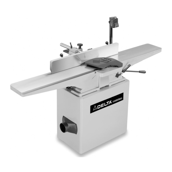
OPERATING INSTRUCTIONS FOREWORD Delta Model 37-380 is a 8" Professional Jointer with a cutting capacity of 8" (203mm) width, 1/8" depth (3mm max.) and 1/2" (13mm) rabbeting. Unit includes; heavy-duty 1-1/2 hp, 120/240 volt induction motor, stand, dust chute, fence, three- knife cutterhead, cutterhead guard, and push blocks. - Page 7 1. Jointer 2. Fence Carriage Assembly 3. Cutterhead Pulley Guard/Carriage Mounting Bracket 4. Table Raising Handle 5. Switch Mounting Bracket 6. Cutterhead Guard 7. Fence Tilting Handles (2) 8. Fence JOINTER PARTS Fig. 2 9. Push Blocks (2) 10. 6mm Hex Wrench 11.
-
Page 8: Jointer To Stand
16. Stand with Pre-Wired Switch 17. Dust Chute 18. V-Belt 19. Pulley 20. 3/8-16x2" Hex Head Screw (3) 21. M8x1.25x55mm Hex Socket Head Screw (4) 22. M8x1.25x25mm Hex Socket Head Screw (2) 23. M8x1.25x20mm Hex Socket Head Screw (2) 24. M8x1.25x16mm Hex Socket Head Screw (2) 25. - Page 9 2. Remove the four bolts that attach the motor (A) Fig. 5 to top of the stand. NOTE: SAVE THESE BOLTS AS THEY WILL BE USED TO ATTACH THE MOTOR TO THE MOUNTING BRACKETS. 3. Align the holes in the motor mounting plate (B) Fig. 5A with the four holes in the two motor mounting brackets (C).
-
Page 10: Aligning Pulleys
ASSEMBLING MOTOR PULLEY Assemble motor pulley (K) Fig. 10, to motor shaft with the hub of the pulley in the outer position as shown. Make certain key (L) is inserted in the keyway of the pulley and motor shaft, then tighten set screw (M) using the 3 mm hex wrench (not shown). -
Page 11: Assembling Fence
2. Using the supplied 6mm hex wrench (E) Fig. 14, fasten bracket (C) onto jointer base (G). Place a M8.1 lockwasher then an M8 flat washer on an M8x1.25x55mm hex socket head screw. Insert the screw (D) Fig. 14, through the hole in bracket (C), and thread the screw into the jointer base (G), and tighten securely. -
Page 12: Assembling Cutterhead Guard
2. Fig. 18 illustrates fence properly mounted. 3. Thread shorter fence handle (E ) Fig.19, into infeed end of fence (A) and longer fence handle (G) into outfeed end as shown. ASSEMBLING CUTTERHEAD GUARD 1. Remove set screw (not shown) from cutterhead guard post (F) with the 2.5mm hex wrench. - Page 13 ASSEMBLING SWITCH AND MOUNTING BRACKET 1. Align the two holes in the switch mounting bracket (A) Fig 22, with the two holes (D) in the back of the infeed table (B). Place an M8.1 lockwasher (E) Fig. 22, then an M8 flat washer (F), on an M8x1.25x16mm hex socket head screw (C).
-
Page 14: Operating Controls And Adjustments
OPERATING CONTROLS AND ADJUSTMENTS STARTING AND STOPPING JOINTER 1. The on/off switch is located underneath the switch shield (B) Fig. 31. To start the jointer, move switch (A) up to the “ON” position. 2. To turn the jointer “OFF”, push down on switch shield (B) Fig. - Page 15 2. Raise or lower the infeed table adjustment lever (C) Fig. 35. 3. IMPORTANT: When lowering the infeed table, a depth stop (D) Fig. 35, will automatically stop the table at a 1/8" depth-of-cut. To move the table past this point, the depth stop (D) Fig.
- Page 16 KNIFE ADJUSTMENTS In order to do accurate work, the knives must be exactly level with the outfeed table. To check and adjust, proceed as follows: D I S C O N N E C T M A C H I N E F R O M POWER SOURCE.
-
Page 17: Adjusting Table Gibs
ADJUSTING TABLE GIBS “Gibs”’ are provided to take up any play that may develop between the mating dovetailed ways of the base and the infeed and outfeed tables, due to excessive wear. The gib for the infeed table is shown at (A) Fig. 46. Proper gib adjustment is necessary for the functioning of the jointer. -
Page 18: Fence Operation
FENCE OPERATION The fence can be moved across the table and can tilt 45 degrees right or left at any position on the table as follows: NOTE: SWITCH HAS BEEN REMOVED FOR CLARITY OF ILLUSTRATIONS ONLY. 1. To move the fence across the table, loosen lock handle (A) Fig. -
Page 19: Removing, Replacing, And Resetting Knives
4. Rotate flip stop (F) Fig. 54, and tilt the fence outward as far as it will go and tighten locking handle (D). Place a square (K) on the table and against the fence to check if the fence is 45 degrees outward to the table. 5. - Page 20 K N I V E S M U S T B E I N S T A L L E D CORRECTLY AS SHOWN IN FIG. 58. 8. The knives are adjusted correctly when the cutting edge of the knife extends out .060” from the cutterhead diameter.
-
Page 21: Operation
The following directions will give the beginner a start on jointer operations. Use scrap pieces of lumber to check settings and to get the feel of the operations before attempting regular work. THE KNIVES ON THE JOINTER WILL NOT WEAR EVENLY BY FEEDING THE WOOD THROUGH THE SAME SPOT ON THE TABLE EVERY TIME. -
Page 22: Taper Cuts
SURFACING Surfacing is identical to the jointing operation except for the position of the workpiece. For surfacing, the major flat surface of the workpiece is placed on the infeed table of the jointer with the narrow edge of the workpiece against the fence, as shown in Fig. -
Page 23: Maintenance And Repairs
SURFACING WARPED PIECES If the wood to be surfaced is dished or warped, take light cuts until the surface is flat. Avoid forcing such material down against the table; excessive pressure will spring it while passing the knives, and it will spring back and remain curved after the cut is completed. -
Page 24: Constructing A Push Stick
CONSTRUCTING A PUSH STICK Narrow pieces of stock that are close to 10 inch minimum length should be handled with a push stick and push block. The Fig. below is a pattern for a push stick. - Page 25 NOTES...
- Page 26 NOTES...
-
Page 27: Parts, Service Or Warranty Assistance
A complete line of accessories is available from your Delta Supplier, Porter-Cable • Delta Factory Service Centers, and Delta Authorized Service Stations. Please visit our Web Site www.deltamachinery.com for a catalog or for the name of your nearest supplier. Since accessories other than those offered by Delta have not been tested with this product, use of such accessories could be hazardous. - Page 28 PORTER-CABLE (CENTROS DE SERVICIO DE PORTER-CABLE Parts and Repair Service for Porter-Cable (Obtenga Refaccion de Partes o Servicio para su Herramienta en los Siguientes Centros de Porter-Cable ARIZONA ILLINOIS Tempe 85282 (Phoenix) Addison 60101 (Chicago) 2400 West Southern Avenue 400 South Rohlwing Rd. Suite 105 Phone: (630) 424-8805 Phone: (602) 437-1200...
Need help?
Do you have a question about the 37-380 and is the answer not in the manual?
Questions and answers