Desa VC42NE SERIES Owner's Operation And Installation Manual
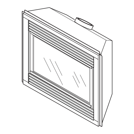
Direct-vent fireplace
Hide thumbs
Also See for VC42NE SERIES:
- Owner's operation and installation manual (38 pages) ,
- Owner's operation and installation manual (40 pages)
Table of Contents
Advertisement
Quick Links
OWNER'S OPERATION AND INSTALLATION MANUAL
WARNING: If the information in this manual is not fol-
lowed exactly, a fire or explosion may result causing
property damage, personal injury or loss of life.
— Do not store or use gasoline or other flammable
vapors and liquids in the vicinity of this or any other
appliance.
— WHAT TO DO IF YOU SMELL GAS
• Do not try to light any appliance.
• Do not touch any electrical switch; do not use any
phone in your building.
• Immediately call your gas supplier from a neighbor's
phone. Follow the gas supplier's instructions.
• If you cannot reach your gas supplier, call the fire
department.
— Installation and service must be performed by a quali-
fied installer, service agency or the gas supplier.
For more information, visit www.desatech.com
DIRECT-VENT FIREPLACE
NATURAL GAS MODELS
(V)VC42NE SERIES
PROPANE/LP GAS MODELS
(V)VC42PE SERIES
Save this manual for future reference.
Advertisement
Table of Contents

Related Manuals for Desa VC42NE SERIES


Summary of Contents for Desa VC42NE SERIES
- Page 1 • If you cannot reach your gas supplier, call the fire department. — Installation and service must be performed by a quali- fied installer, service agency or the gas supplier. Save this manual for future reference. For more information, visit www.desatech.com NATURAL GAS MODELS (V)VC42NE SERIES (V)VC42PE SERIES...
-
Page 2: Table Of Contents
WARNING: Improper installation, adjustment, altera- tion, service or maintenance can cause injury or prop- erty damage. Refer to this manual for correct installation and operational procedures. For assistance or addi- tional information consult a qualified installer, service agency or the gas supplier. This appliance may be installed in an aftermarket,* per- manently located, manufactured (mobile) home, where not prohibited by local codes. -
Page 3: Safety Information
SAFETy INFORMATION WARNING: This product con- tains and/or generates chemicals known to the State of California to cause cancer or birth defects or other reproductive harm. IMPORTANT: Read this owner’s manual carefully and completely before trying to assemble, operate or service this log set. Improper use of this log set can cause serious injury or death from burns, fire, explosion, electrical shock and... -
Page 4: Product Identification
SAFETy INFORMATION Continued Carefully supervise young chil- dren when they are in the room with fireplace. Keep the area around your fireplace clear of combustible materials, gasoline and other flammable vapor or liquids. Do not run fireplace where these are used or stored. 1. -
Page 5: Local Codes
LOCATION AND SPACE REqUIREMENTS Determine the safest and most efficient location for your DESA direct-vent fireplace. Make sure that rafters and wall studs are not in the way of the venting system. Choose a location where the heat output is not affected by drafts, air conditioning ducts, windows or doors. - Page 6 PRE-INSTALLATION PREPARATION Continued • Your fireplace is designed to be used in zero clearance installations. Wall or framing material can be placed directly against any exterior sur- face on the back, sides or top of your fireplace, except where standoff spacers are integrally attached.
-
Page 7: Framing And Finishing
PRE-INSTALLATION PREPARATION Continued FRAMING AND FINISHING Figure 4 shows typical framing of this fireplace. Figure 5 shows framing for corner installation. All minimum clearances must be met. For available accessories for this fireplace, see Accessories on page 35. If you are using a sepa- rate combustible mantel piece, refer to Figure 6 for proper installation height. -
Page 8: Location Of Termination Cap
LOCATION OF TERMINATION CAP TERMINATION CAP A = clearance above grade, veranda, porch, deck, or balcony [*12 inches (30.5mc) minimum] B = clearance to window or door that may be opened [12 inches (30.5cm) minimum] C = clearance to permanently closed window [minimum 12 inches (30.5cm) recommended to prevent condensation on window] D = vertical clearance to ventilated soffit located above the terminal within a horizontal distance of 24 inches (61cm) from the... -
Page 9: Venting Installation Instructions
These models are tested and approved for use with DESA (direct-vent) pipe components and terminations. The venting system must terminate on the outside of the structure and can not be attached to a chimney or flue system serving a separate solid fuel or gas burning appliance. -
Page 10: Venting Installation
VENTING INSTALLATION INSTRUCTIONS Continued INSTALLATION PLANNING There are two basic types of direct-vent in- stallation: • Horizontal Termination • Vertical Termination Horizontal Termination Installation IMPORTANT: Horizontal square terminations require only inner portion of wall firestop. Hori- zontal installations using round termination require exterior portion of wall firestop (see Figure 14, page 12). - Page 11 VENTING INSTALLATION INSTRUCTIONS Continued WARNING: Do not recess vent termination into any wall. This will cause a fire hazard. Noncombustible Exterior Wall: horizontal vent cap in the center of the 8 round hole and attach to the exterior wall with four wood screws provided.
- Page 12 VENTING INSTALLATION INSTRUCTIONS Continued Minimum Pipe Overlap 1 " Direct-Vent Pipe Wall Firestop Maintain 1" Minimum Air Space Around Outer Pipe When Penetrating a Wall " x 10 " Framed Opening Exterior Wall with Vinyl Siding Figure 13 - Typical Horizontal Termination Cap Mounting with Additional Siding Standoff Installed Horizontal Termination Configurations...
-
Page 13: Venting Installation Instructions
VENTING INSTALLATION INSTRUCTIONS CORNER INSTALLATION Recommended Applications: • Corner ground floor installation • Ground floor installation where pipe vents horizon- tally through wall (over 12" horizontal pipe) • Basement installation where one foot clearance from ground to termination is possible Not to Exceed (H) Limits Square Termination... - Page 14 VENTING INSTALLATION INSTRUCTIONS HORIZONTAL SYSTEM INSTALLATION USING TWO 90° ELBOWS The following configurations show the minimum vertical rise requirements for a horizontal system using two 90° elbows. Venting with Two 90° Elbows Vertical (V) Horizontal (H 5' min. 2' max. 6' min.
- Page 15 VENTING INSTALLATION INSTRUCTIONS Continued INSTALLATION FOR VERTICAL TERMINATION Note: Vertical restrictor must be installed in all vertical installations. 1. Determine the route your vertical venting will take. If ceiling joists, roof rafters or other framing will obstruct the venting system, consider an offset (see Figure 19) to avoid cut- ting load bearing members.
- Page 16 VENTING INSTALLATION INSTRUCTIONS Continued 5. Place the flashing over the pipe section(s) extending through the roof. Secure the base of the flashing to the roof and framing with roof- ing nails. Be sure roofing material overlaps the top edge of the flashing as shown in Figure 19, page 15.
- Page 17 (Vertical Round High Wind Termination 12' max. 18' max. HIGH ALTITUDE INSTALLATION 20' max. Your DESA direct-vent fireplace has been tested and approved for elevations from 0-2000 ) = 40' max. feet (USA) and elevations from 0-4500 feet (Canada). When installing this fireplace at an elevation...
- Page 18 VENTING INSTALLATION INSTRUCTIONS Continued PARTS LIST FOR VENTING KITS AND COMPONENTS DESA (5"/8") Pipe & Vent Kits Number Description P58-6 6" Section Double Wall Pipe, Galvanized P58-12 12" Section Double Wall Pipe, Galvanized P58-24 24" Section Double Wall Pipe, Galvanized P58-36 36"...
-
Page 19: Fireplace Installation
FIREPLACE INSTALLATION CHECK GAS TYPE Use proper gas type for the fireplace unit you are installing. If you have conflicting gas types, do not install fireplace. See retailer where you purchased the fireplace for proper fireplace according to your gas type or to purchase gas conversion kit (see Accessories, page 35). - Page 20 FIREPLACE INSTALLATION Continued CAUTION: Never touch the blower wheel while in operation. 9. Check to make sure that the power cord is com- pletely clear of the blower wheel and that there are no other foreign objects in blower wheel. Turn blower on and check for operation.
- Page 21 FIREPLACE INSTALLATION Continued 7. Check to make sure that the power cord is com- pletely clear of the blower wheel and that there are no other foreign objects in blower wheel. Also double check all wire leads and make sure wire routing is not pinched or in a precarious position.
- Page 22 FIREPLACE INSTALLATION Continued CAUTION: Use only new, black iron or steel pipe. Inter- nally-tinned copper tubing may be used in certain areas. Check your local codes. Use pipe of 1/2" diameter or greater to allow proper gas volume to fireplace. If pipe is too small, undue loss of volume will occur.
-
Page 23: Checking Gas Connections
FIREPLACE INSTALLATION Continued Flexible Equipment Gas Line Shutoff Do NOT Valve Kink 1/2" NPT Inlet Incoming Pressure Gas Line Note: Wire Connections Not Shown for Clarity Figure 32 - Connecting Flexible Gas Line to Electronic Valve CHECKING GAS CONNECTIONS WARNING: Test all gas piping and connections , internal and external to unit, for leaks after installing or servicing. - Page 24 FIREPLACE INSTALLATION Continued PRESSURE TESTING FIREPLACE GAS CONNECTIONS 1. Open equipment shutoff valve (see Figure 33, page 23). 2. Open propane/LP supply tank valve for propane/LP fireplace or main gas valve located on or near gas meter for natural gas fireplace.
-
Page 25: Brick Panels
FIREPLACE INSTALLATION Continued 4. Remount the new frame at the hinge with five new screws before closing door. This will ensure seating of the gasket. 5. Close glass door frame. Lock latches by placing the bar under the tab on door and pushing down and back on latch (see Figure 37, page 24). -
Page 26: Wall Switch Installation
FIREPLACE INSTALLATION Continued 7. Remove three screws from deflector shield on the inside top of firebox. Set shield and screws aside. 8. Install rear brick panel first. Rest bottom edge of panel on back edge of burner assembly (see Figure 39). 9. -
Page 27: Wiring Diagram
IGNITOR LEAD ORANGE 116237-01E WIRING DIAGRAM PILOT GREEN www.desatech.com BLUE TRANSFORMER WHITE BLACK GROUND... -
Page 28: Operating Fireplace
OPERATING FIREPLACE FOR YOUR SAFETY READ BEFORE LIGHTING WARNING: If you do not fol- low these instructions exactly, a fire or explosion may result causing property damage, per- sonal injury or loss of life. A. This appliance has a pilot which must be lighted by hand. -
Page 29: Inspecting Burners
OPERATING FIREPLACE Continued OPTIONAL REMOTE OPERATION Note: The WRC receiver and hand-held re- mote control kit must be purchased separately (see Accessories, page 35). Follow installation instructions on page 26. 1. Turn equipment shutoff valve to ON position. You can now turn the burner on and off with the hand-held remote control unit. -
Page 30: Cleaning And Maintenance
CLEANING AND MAINTENANCE WARNING: Turn off fireplace and let cool before cleaning. CAUTION: You must keep con- trol areas, burners and circulating air passageways of fireplace clean. Inspect these areas of fireplace before each use. Have fireplace inspected yearly by a qualified service person. -
Page 31: Troubleshooting
CLEANING AND MAINTENANCE Continued VENTING SYSTEM Conduct annual inspection of the venting system following these guidelines: 1. Check areas of venting system that are exposed to the weather for corrosion (rust spots or streaks and, in extreme cases, holes). Have these items replaced immediately by a qualified service person. - Page 32 OBSERVED PROBLEM Pilot will not stay lit No gas to burner, although wall switch and valve are set to the ON position Frequent pilot outage Fireplace produces a clicking/tick- ing noise just after burner is lit or shut off Slight smoke or odor during initial operation TROUbLEShOOTING Continued...
- Page 33 WARNING: If you smell gas • Shut off gas supply. • Do not try to light any appliance. • Do not touch any electrical switch; do not use any phone in your building. • Immediately call your gas supplier from a neighbor’s phone. Fol- low the gas supplier’s instructions.
-
Page 34: Replacement Parts
If so, contact DESA’s Customer Service Department at 1-866-672-6040. When calling, please have your model and serial numbers of your heater ready. You can also visit DESA’s technical service web site at www.desatech.com SPECIFICATIONS VC42NE and VVC42NE •... -
Page 35: Accessories
Purchase these fireplace accessories from your local retailer. If they can not supply these accessories, call DESA’s Sales Department at 1-866-672-6040. for information. You can also write to the address listed on the back page of this manual. BRICK LINER... -
Page 36: Illustrated Parts Breakdown And Parts List
ILLUSTRATED PARTS bREAkDOWN MODELS VC42NE, VVC42NE, VC42PE AND VVC42PE www.desatech.com 116237-01E... -
Page 37: Parts List
MODELS VC42NE, VVC42NE, VC42PE AND VVC42PE This list contains replaceable parts used in your fireplace. When ordering parts, follow the instructions listed under Replacement Parts on page 34 of this manual. PART NUMBER DESCRIPTION Firebox Assembly Face Weldment 108328-01 Door Assembly 108328-02 Door Assembly (V Models Only) 108331-01... - Page 38 ILLUSTRATED PARTS bREAkDOWN BURNER ASSEMBLY FOR MODELS VC42NE, VC42PE, VVC42NE AND VVC42PE www.desatech.com 116237-01E...
- Page 39 BURNER ASSEMBLY FOR MODELS VC42NE, VC42PE, VVC42NE AND VVC42PE This list contains replaceable parts used in your fireplace. When ordering parts, follow the instructions listed under Replacement Parts on page 34 of this manual. PART NO. 26808 11107 11102 116344-01 111288-02 108866-01 Elec.
-
Page 40: Warranty Information
We make no other warranty, expressed or implied. DESA warrants this product to be free from defects in materials and components for two (2) years from the date of first purchase, provided that the product has been properly installed, operated and maintained in accordance with all applicable instructions.