HP 273914-B21 - Smart Array 6404/256 RAID Controller User Manual
Smart array 6400 series controllers user guide
Hide thumbs
Also See for 273914-B21 - Smart Array 6404/256 RAID Controller:
- Reference manual (112 pages) ,
- User manual (42 pages) ,
- Technology brief (32 pages)
Table of Contents
Advertisement
Quick Links
Download this manual
See also:
Reference Manual
Advertisement
Table of Contents

Related Manuals for HP 273914-B21 - Smart Array 6404/256 RAID Controller


Summary of Contents for HP 273914-B21 - Smart Array 6404/256 RAID Controller
-
Page 1: User Guide
HP Smart Array 6400 Series Controllers User Guide for HP ProLiant Servers January 2005 (Fifth Edition) Part Number 309135-005... - Page 2 © Copyright 2003-2005 Hewlett-Packard Development Company, L.P. The information contained herein is subject to change without notice. The only warranties for HP products and services are set forth in the express warranty statements accompanying such products and services. Nothing herein should be construed as constituting an additional warranty. HP shall not be liable for technical or editorial errors or omissions contained herein.
-
Page 3: Table Of Contents
Contents Hardware features Board components..........................7 Expansion module components......................8 Controller specifications and attributes....................9 Determining the correct installation procedure for the server Unused autoconfigurable server......................11 Unused non-autoconfigurable server ....................12 Previously configured server......................12 Installing the controller hardware Before beginning the installation ....................... - Page 4 HP Smart Array 6400 Series Controllers User Guide Installing device drivers and Management Agents Installing device drivers ........................33 Installing Management Agents ......................34 Upgrading or replacing controller options Replacing a battery..........................35 Replacing the expansion module ....................... 37 Replacing, moving, or adding hard drives Identifying the status of a hard drive....................
- Page 5 Contents Korean notice A&B ........................... 62 Battery replacement notice......................... 62 Taiwan battery recycling notice....................63 Acronyms and abbreviations Index...
-
Page 7: Hardware Features
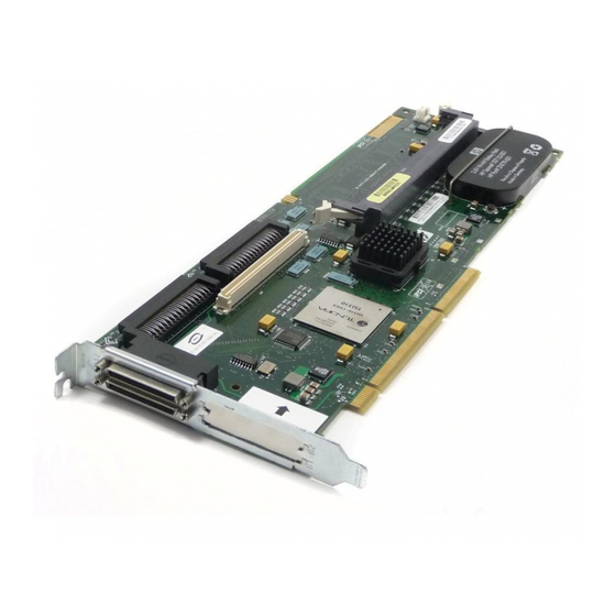
Hardware features In this section Board components ..........................7 Expansion module components ......................8 Controller specifications and attributes ..................9 Board components Item ID Description Internal SCSI connector, port A1 (do not use simultaneously with item 3) Internal SCSI connector, port A2 (do not use simultaneously with item 4) External SCSI connector, port A1 (do not use simultaneously with item 1) -
Page 8: Expansion Module Components
HP Smart Array 6400 Series Controllers User Guide Item ID Description Battery-backed cache module Connector for expansion board Expansion module components An expansion module is used to add two extra external channels to an SA6402 controller, converting it to an SA6404 controller. Item ID Description 0–7... -
Page 9: Controller Specifications And Attributes
Hardware features During POST, each component controller loads its own instance of the required driver and sets its own configuration using ORCA. The dual controller is displayed in both Systems Insight Manager and ACU as two separate entities in one slot. In these utilities, the slot number label for the expansion module has a lowercase b suffix, while the slot number label for the main controller has no suffix. - Page 10 HP Smart Array 6400 Series Controllers User Guide For more information about the controller features and specifications, and for information about system requirements, refer to the HP website (http://www.hp.com/products/smartarray).
-
Page 11: Determining The Correct Installation Procedure For The Server
Determining the correct installation procedure for the server In this section Unused autoconfigurable server ....................11 Unused non-autoconfigurable server....................12 Previously configured server ......................12 Unused autoconfigurable server New HP ProLiant server models self-configure when they are powered up for the first time. For more information about the autoconfiguration process, refer to the server-specific setup and installation guide or the HP ROM-Based Setup Utility User Guide. -
Page 12: Unused Non-Autoconfigurable Server
HP Smart Array 6400 Series Controllers User Guide 6. Install the operating system and device drivers ("Installing device drivers" on page 33). Instructions are provided with the CD that is supplied in the controller kit. 7. Create and format additional logical drives if desired ("Configuring an array" on page 25). - Page 13 Determining the correct installation procedure for the server 3. If the new controller is to be the boot device, install the device drivers for the operating system ("Installing device drivers" on page 33). Otherwise, continue with step 4. IMPORTANT: The expansion module on the SA6404 controller cannot be used as a boot device.
-
Page 15: Installing The Controller Hardware
Installing the controller hardware In this section Before beginning the installation....................15 Preparing the server ........................15 Installing the controller board.......................16 Connecting storage devices ......................17 Before beginning the installation Before beginning the installation procedure, visit the HP website (http://www.hp.com/support) to confirm that you have the latest version of each driver and utility file needed. -
Page 16: Installing The Controller Board
HP Smart Array 6400 Series Controllers User Guide CAUTION: In systems that use external data storage, be sure that the server is the first unit to be powered down and the last to be powered back up. Taking this precaution ensures that the system does not erroneously mark the drives as failed when the server is powered 3. -
Page 17: Connecting Storage Devices
Installing the controller hardware 7. Replace the access panel, and secure it with screws if any are present. CAUTION: Do not operate the server for long periods without the access panel. Operating the server without the access panel results in improper airflow and improper cooling that can lead to thermal damage. -
Page 18: Connecting External Storage
HP Smart Array 6400 Series Controllers User Guide When you have finished installing drives, continue with the next step. If the drives are hot-pluggable, go to step 3. If the drives are not hot-pluggable, go to step 4. 3. Attach the internal point-to-point SCSI cable (provided with the server) from the internal connector of the controller to the hot-plug drive cage. - Page 19 Installing the controller hardware SCSI cable type Cable length Option kit number Cable assembly number External VHDCI cable 1.8 m (6 ft) 341174-B21 313374-001 3.7 m (12 ft) 341175-B21 313374-002 7.3 m (24 ft) 164604-B21 313374-004 11.9 m (39 ft) 150214-B21 313374-005 Internal multi-device cable...
-
Page 21: Updating The Firmware
Updating the firmware In this section Methods for updating the firmware ....................21 Methods for updating the firmware To update the firmware on the server, controller, or hard drives, use Smart Components. These components are available on the Firmware Maintenance CD. A more recent version of a particular server or controller component might be available on the support page of the HP website (http://www.hp.com/support). -
Page 23: Configuring The Server
Configuring the server In this section Configuring the server ........................23 Configuring the server After installing the controller hardware and updating the firmware, use RBSU to configure the server. NOTE: The 2-channel expansion module is a controller in its own right. Thus, the Smart Array 6404 Controller is actually two 2-channel controllers sharing one PCI-X connector. -
Page 25: Configuring An Array
Configuring an array In this section Introduction ..........................25 Comparing the utilities .........................26 Using ORCA ..........................27 Using ACU ...........................28 Using CPQONLIN ........................28 Introduction HP provides three utilities for manually configuring an array on a Smart Array controller: ORCA—A simple ROM-based configuration utility ACU—A versatile, browser-based utility that provides maximum control over configuration parameters CPQONLIN—A menu-based configuration utility specifically for servers... -
Page 26: Comparing The Utilities
HP Smart Array 6400 Series Controllers User Guide For conceptual information about arrays, logical drives, and fault-tolerance methods, and for information about default array configuration settings, refer to the HP Array Configuration Utility User Guide. This document is available on the Documentation CD that is provided in the controller kit. -
Page 27: Using Orca
Configuring an array Using ORCA 1. Power up the server. POST runs, and any array controllers that are in the server are initialized one at a time. During each controller initialization process, POST halts for several seconds while an ORCA prompt message appears. -
Page 28: Using Acu
HP Smart Array 6400 Series Controllers User Guide You can now create another logical drive by repeating the previous steps. NOTE: Newly created logical drives are invisible to the operating system. To make the new logical drives available for data storage, format them using the instructions given in the operating system documentation. -
Page 29: Setting Drive Rebuild, Expand Priority, And Accelerator Ratio
Configuring an array If the controller is connected to at least one logical drive, CPQONLIN continues in manual configuration mode. Use the arrow and Enter keys to navigate around the screen and set up the logical drive. To get online help at any time, press the F1 key. -
Page 30: Expanding An Array
HP Smart Array 6400 Series Controllers User Guide Accelerator ratio The controller has an onboard cache called an Array Accelerator, which performs both write-posting and read-ahead caching. The setting in CPQONLIN determines the amount of memory allocated to the read and write caches. For example, if the accelerator ratio is set to Read 75%:Write 25%, 75% of Array Accelerator cache is dedicated to read-ahead cache and 25% is dedicated to the write-posting cache. -
Page 31: Migrating Raid Level And Stripe Size Online
Configuring an array Migrating RAID level and stripe size online Using CPQONLIN, you can modify both the RAID level and stripe size of an existing logical drive while online. To migrate a drive: 1. Select the drive setting option under the logical drive menu for the drive you intend to modify. -
Page 33: Installing Device Drivers And Management Agents
Installing device drivers and Management Agents In this section Installing device drivers........................33 Installing Management Agents.....................34 Installing device drivers The drivers for the controller are located on the Support Software CD or the SmartStart CD that is provided in the controller kit. Updates are posted to the HP website (http://www.hp.com/support). -
Page 34: Installing Management Agents
HP Smart Array 6400 Series Controllers User Guide Installing Management Agents NOTE: The 2-channel expansion module is a controller in its own right. Thus, the Smart Array 6404 Controller is actually two 2-channel controllers sharing one PCI-X connector. This dual controller is displayed in both Systems Insight Manager and ACU as two separate entities in one slot. -
Page 35: Upgrading Or Replacing Controller Options
Upgrading or replacing controller options In this section Replacing a battery ........................35 Replacing the expansion module....................37 Replacing a battery WARNING: There is a risk of explosion, fire, or personal injury if the battery pack is not properly handled. Refer to "Battery replacement notice (on page 62)"... - Page 36 HP Smart Array 6400 Series Controllers User Guide b. Pull the cache module out of the DIMM slot (2). 3. If the main cache battery must be replaced: a. Press the battery retainer tabs down, and push them through to the other side of the cache board (1).
-
Page 37: Replacing The Expansion Module
Upgrading or replacing controller options b. While holding the battery in one hand, pull the plastic retainer tabs up and push them through to the other side of the controller board (2). 5. Replace whichever battery is degraded. 6. Reinstall the batteries on the cache board and the controller board. 7. - Page 38 HP Smart Array 6400 Series Controllers User Guide 3. Secure the expansion module to the controller board by inserting and tightening the appropriate screw (provided in the kit) in the back of the controller board (4). To remove the expansion module, reverse this procedure.
-
Page 39: Replacing, Moving, Or Adding Hard Drives
Replacing, moving, or adding hard drives In this section Identifying the status of a hard drive ....................39 Recognizing hard drive failure .....................41 Replacing hard drives ........................43 Moving drives and arrays ......................47 Adding drives ..........................49 Identifying the status of a hard drive When a drive is configured as a part of an array and connected to a powered-up controller, the condition of the drive can be determined from the illumination pattern of the hard drive status lights (LEDs). -
Page 40: Hot-Plug Scsi Hard Drive Led Combinations
HP Smart Array 6400 Series Controllers User Guide Hot-plug SCSI hard drive LED combinations Activity Online Fault LED Interpretation LED (1) LED (2) On, off, or On or off Flashing A predictive failure alert has been received for this drive. flashing Replace the drive as soon as possible. -
Page 41: Recognizing Hard Drive Failure
Replacing, moving, or adding hard drives Recognizing hard drive failure A steadily glowing Fault LED indicates that that drive has failed. Other means by which hard drive failure is revealed are: The amber LED on the front of a storage system illuminates if failed drives are inside. -
Page 42: Compromised Fault Tolerance
HP Smart Array 6400 Series Controllers User Guide RAID 1+0 configurations can tolerate multiple drive failures as long as no failed drives are mirrored to one another. RAID 5 configurations can tolerate one drive failure. RAID ADG configurations can tolerate simultaneous failure of two drives. Compromised fault tolerance If more hard drives fail than the fault-tolerance method allows, fault tolerance is compromised, and the logical drive fails. -
Page 43: Replacing Hard Drives
Replacing, moving, or adding hard drives 3. Replace any failed drives. 4. After you have replaced the failed drives, fault tolerance may again be compromised. If so, cycle the power again. If the 1779 POST message is displayed: a. Press the F2 key to re-enable the logical drives. b. - Page 44 HP Smart Array 6400 Series Controllers User Guide If you set the SCSI ID jumpers manually: Check the ID value of the removed drive to be sure that it corresponds to the ID of the drive marked as failed. Set the same ID value on the replacement drive to prevent SCSI ID conflicts.
-
Page 45: Automatic Data Recovery (Rebuild)
Replacing, moving, or adding hard drives In RAID ADG configurations, any two drives in the array can be replaced simultaneously. In RAID 1+0 configurations, any drives that are not mirrored to other removed or failed drives can be simultaneously replaced offline without data loss. -
Page 46: Upgrading Hard Drive Capacity
HP Smart Array 6400 Series Controllers User Guide The number of drives in the array (for RAID 5 and RAID ADG) Allow approximately 15 minutes per gigabyte for the rebuild process to be completed. This figure is conservative, and newer drive models usually require less time to rebuild. -
Page 47: Moving Drives And Arrays
Replacing, moving, or adding hard drives CAUTION: Because it can take up to 15 minutes per gigabyte to rebuild the data in the new configuration, the system is unprotected against drive failure for many hours while a given drive is upgraded. Perform drive capacity upgrades only during periods of minimal system activity. - Page 48 HP Smart Array 6400 Series Controllers User Guide The controller is not reading from or writing to any of the spare drives in the array. The controller is not running capacity expansion, capacity extension, or RAID or stripe size migration. The controller is using the latest firmware version (recommended).
-
Page 49: Adding Drives
Replacing, moving, or adding hard drives c. Open ACU and navigate to the controller that contained the RAID ADG volume. ACU displays the missing RAID ADG volume using a different icon to indicate that the volume is unavailable. d. Delete the RAID ADG volume. e. - Page 50 HP Smart Array 6400 Series Controllers User Guide The expansion process is illustrated in the following figure, in which the original array (containing data) is shown with a dashed border and the newly added drives (containing no data) are shown unshaded. The array controller adds the new drives to the array and redistributes the original logical drives over the enlarged array one logical drive at a time.
-
Page 51: Diagnosing Array Problems
Diagnosing array problems In this section Controller board runtime LEDs ....................51 Cache module LEDs........................53 Diagnostic tools ..........................54 Controller board runtime LEDs NOTE: During server power-up, each runtime LED illuminates randomly until POST has finished. LED ID Color LED name and interpretation Amber CR100: Diagnostics Error LED. - Page 52 HP Smart Array 6400 Series Controllers User Guide LED ID Color LED name and interpretation Green CR104: Command Outstanding LED. The controller is working on a command. Blue CR105: Heartbeat LED. This LED flashes every 2 seconds, unless the controller is malfunctioning. Green CR106: Gas Pedal LED.
-
Page 53: Cache Module Leds
Diagnosing array problems Cache module LEDs Item 1 Item 2 Interpretation (amber (green LED) LED) Steady glow The cache batteries are being charged. Fast blink The cache microcontroller is waiting for the host controller to communicate. Steady glow One of the following situations is occurring: •... -
Page 54: Diagnostic Tools
HP Smart Array 6400 Series Controllers User Guide Diagnostic tools Several diagnostic tools provide feedback about problems with arrays. The most important are: This utility is available on the SmartStart CD. The meanings of the various ADU error messages are provided in the HP Servers Troubleshooting Guide. POST messages Smart Array controllers produce diagnostic error messages at reboot. -
Page 55: Electrostatic Discharge
Electrostatic discharge In this section Preventing electrostatic discharge ....................55 Grounding methods to prevent electrostatic discharge..............56 Preventing electrostatic discharge To prevent damaging the system, be aware of the precautions you need to follow when setting up the system or handling parts. A discharge of static electricity from a finger or other conductor may damage system boards or other static- sensitive devices. -
Page 56: Grounding Methods To Prevent Electrostatic Discharge
HP Smart Array 6400 Series Controllers User Guide Grounding methods to prevent electrostatic discharge Several methods are used for grounding. Use one or more of the following methods when handling or installing electrostatic-sensitive parts: Use a wrist strap connected by a ground cord to a grounded workstation or computer chassis. -
Page 57: Regulatory Compliance Notices
Regulatory compliance notices In this section Federal Communications Commission notice ................57 Canadian notice (Avis Canadien) ....................60 European Union regulatory notice....................60 BSMI notice..........................61 Japanese notice ..........................61 Korean notice A&B ........................62 Battery replacement notice ......................62 Federal Communications Commission notice Part 15 of the Federal Communications Commission (FCC) Rules and Regulations has established Radio Frequency (RF) emission limits to provide an interference-free radio frequency spectrum. -
Page 58: Class A Equipment
HP Smart Array 6400 Series Controllers User Guide Class A equipment This equipment has been tested and found to comply with the limits for a Class A digital device, pursuant to Part 15 of the FCC Rules. These limits are designed to provide reasonable protection against harmful interference when the equipment is operated in a commercial environment. -
Page 59: Declaration Of Conformity For Products Marked With The Fcc Logo, United States Only
Modifications The FCC requires the user to be notified that any changes or modifications made to this device that are not expressly approved by Hewlett-Packard Company may void the user’s authority to operate the equipment. Cables Connections to this device must be made with shielded cables with metallic RFI/EMI connector hoods in order to maintain compliance with FCC Rules and Regulations. -
Page 60: Canadian Notice (Avis Canadien)
*For a notified body number refer to the product regulatory label. Compliance with these directives implies conformity to harmonized European standards (European Norms) which are listed on the EU Declaration of Conformity issued by Hewlett-Packard for this product or product family. -
Page 61: Bsmi Notice
Regulatory compliance notices BSMI notice Japanese notice... -
Page 62: Korean Notice A&B
HP Smart Array 6400 Series Controllers User Guide Korean notice A&B Class A equipment Class B equipment Battery replacement notice This component uses a nickel metal hydride (NiMH) battery pack. WARNING: There is a risk of explosion, fire, or personal injury if a battery pack is mishandled. -
Page 63: Taiwan Battery Recycling Notice
Regulatory compliance notices Batteries, battery packs, and accumulators should not be disposed of together with the general household waste. To forward them to recycling or proper disposal, use the public collection system or return them by established parts return methods to HP, an authorized HP Partner, or one of their agents. For more information about battery replacement or proper disposal, contact an authorized reseller or an authorized service provider. -
Page 65: Acronyms And Abbreviations
Acronyms and abbreviations Array Configuration Replicator Array Configuration Utility Advanced Data Guarding (also known as RAID 6) Array Diagnostics Utility BBWC battery-backed write cache CPQONLIN NetWare Online Array Configuration Utility ORCA Option ROM Configuration for Arrays POST Power-On Self-Test... - Page 66 HP Smart Array 6400 Series Controllers User Guide RAID redundant array of inexpensive (or independent) disks RBSU ROM-Based Setup Utility Smart Array Systems Insight Manager...
-
Page 67: Index
drivers 33 Index drives, configuring 30 electrostatic discharge 55 error messages 41, 54 European Union notice 60 ACU (Array Configuration Utility) 28 expanding an array 49 adding drives 30, 49 extending logical drive capacity 49 ADU (Array Diagnostic Utility) 54 array capacity expansion 49 array configuration, copying 25 array controller installation overview 11... - Page 68 HP Smart Array 6400 Series Controllers User Guide LEDs, hard drive 39, 40 logical drive capacity extension 49 logical drive, creating 25 ORCA (Option ROM Configuration for Arrays) 27 overview of installation process 11 POST error messages 41, 54 power requirements 9 rebuild, time required for 45 regulatory compliance notices 57 replacing hard drives 39, 43...