Table of Contents
Advertisement
Advertisement
Table of Contents

Related Manuals for Russound COMPOINT SYSTEM


Summary of Contents for Russound COMPOINT SYSTEM
- Page 1 ComPoint ™ The music lover’s intercom solution Instruction Manual...
- Page 2 A grounding plug has two blades and a third grounding prong. If you have any questions, call Russound at The wide blade or the third prong is provided for 800.638.8055 or 603.659.5170.
-
Page 3: Table Of Contents
USER SECTION Programming 21–27 Welcome to ComPoint ™ Overview About this manual Doorbell chimes What’s in your ComPoint system 6–8 Hub ID numbers Using your ComPoint system 9–15 Zone and door station labels Things you’ll need to know Assigning zone labels... -
Page 4: User Section
The Thank you for choosing a Russound solution? The intercom feature lets you con- ComPoint system for your home or busi- tact the person directly, saving you steps ness. While you may already be familiar and time. -
Page 5: About This Manual
Did someone in the family forget their keys? For even greater convenience, your Did a friend drop by? ComPoint offers an ComPoint system can share the speakers in optional module that works with a door your multiroom audio system. When active,... -
Page 6: What's In Your Compoint System
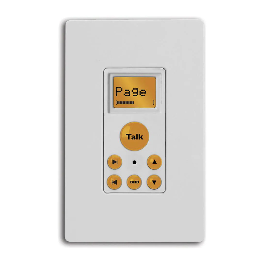
USER SECTION System Components What’s in your ComPoint system ISK1 Basic or ISK2 Advanced Keypad The keypads control the system and serve as your interior ZONE KEYS – Select and indicate zones (Basic Keypad only) communication points. A simple array of keys lets you TALK KEY –... - Page 7 UPDATE PORT MADE IN CHINA ISH1 Hub POWER INPUT – For connecting a Russound ISPS power supply, 15 VDC 3.5 A DOORBELL CHIME GAIN CONTROL – For adjusting the overall volume of the doorbell chimes DOORBELL CHIME SWITCHES – For selecting individual chime tones for one or two door stations HUB ID SWITCHES –...
- Page 8 USER SECTION System Components ISDR1 Door Strike Release Module This optional module provides a connection point for a separate door strike release unit, making it possible to unlock the door from any keypad. OUTPUT CONNECTOR – Punch-down connector for CAT-5 cable to an ISK3 Door Station INPUT CONNECTOR –...
-
Page 9: Using Your Compoint System
Listen mode. If a zone key is lit red on the Basic Keypad, Your ComPoint system is configured with press the key to deselect that zone before either ISK1 Basic or ISK2 Advanced key- you press the Talk key to send a page. -
Page 10: Intercom
USER SECTION Operation Paging (cont’d) If a zone label appears on the Advanced Keypad, use the Next or Previous key to select Page before you press the Talk key. All keypads indicate which zone is sending a page, so you’ll know where it’s coming from. -
Page 11: Door Station Call
USER SECTION Operation Intercom (cont’d) If the selected zone is in Do Not Disturb mode, the display alternately shows the zone label and DND at 1-second intervals and the DND key blinks rapidly for 7 seconds. Receiving an intercom. When the Talk key is pressed on the sending keypad, the receiving keypad indicates which zone is sending the intercom. -
Page 12: Door Strike Release
USER SECTION Operation Door station call (cont’d) Door strike release If your ComPoint system includes optional A door station call takes precedence over ISDR1 Door Strike Release Modules, you paging and intercom sessions and thus can activate them from a keypad to unlock interrupts them if they’re in progress when... -
Page 13: Listen Mode
Basic Keypad Microphone On indication Releasing a door strike on the Advanced Keypad Listen mode You can use your ComPoint system to con- tinuously listen to any single zone from one or more other zones. To do this, first turn... -
Page 14: Do Not Disturb Mode
USER SECTION Operation Listen mode (cont’d) To cancel Listen mode with either type of keypad, deselect the zone you are listening Basic Keypad. To listen to the zone with the to on the keypad in that zone. Listen mode active microphone, press the zone key. The cannot be canceled from any other zone. -
Page 15: Combined Listen And Dnd Modes
USER SECTION Operation Combined Listen and DND modes The Talk key and DND key light up red to indicate the keypad’s microphone is on and You can use DND mode on a keypad you the zone is also in DND mode. On a Basic are listening to in Listen mode. -
Page 16: Installer Section
ISK2 Advanced Keypads are used, ComPoint connects with CAT-5 cable, which zone and door labels. conveys power, ground, audio, and data ISK2 ISH1 ISPS ISK3 ISK3 ISDR1 ISDR1 Six-zone ComPoint system with Advanced Keypads and Door Strike Release Modules... -
Page 17: Ish1 Hub
INSTALLER SECTION Product Summary ISH1 Hub the relays switch the speakers from the audio system to the keypad amplifiers in the affected As the central controller for the ComPoint sys- zones, momentarily interrupting the audio pro- tem, the ISH1 hub performs all communications gram. -
Page 18: Product Summary
INSTALLER SECTION Product Summary/Installation ISK2 Advanced Keypad (cont’d) The ISDR1 obtains its operational power from the hub. The separate door strike release must One of the benefits of the Advanced Keypad is receive voltage from its own power source. the ability to support systems as large as 36 zones, since the ISK2 is able to select any of The ISDR1 passes signals on all leads of the the zones by label. -
Page 19: Device Installation And Trim
ISDR1 modules, loop the door sta- tion cables through the module locations. Each keypad in the system requires one or two external speakers. If the ComPoint system is sharing speakers with an audio system, loop the speaker cables through the keypad loca- tions. -
Page 20: Speaker Connections
DOOR1 and DOOR2. These connec- In a zone where the ComPoint system does not tions must be made according to the T568A share speakers with an audio system, connect a standard as shown below. -
Page 21: Door Strike Release Connections
INSTALLER SECTION Programming Door strike release connections System programming The door strike release module has 110 punch- Overview down connectors for the hub and door station cables. It also has screw terminals for its relay All system programming resides in the ISH1 contacts that accept up to 14 AWG stranded hub. -
Page 22: Doorbell Chimes
To select the chimes, set the switches as Hub ID numbers shown in the table below. In any ComPoint system, there must be a hub with ID number 1. In a multiple-hub system, Doorbell Chime Switch Settings (0 = Down, 1 = Up) each hub’s ID number must be unique. -
Page 23: Zone And Door Station Labels
INSTALLER SECTION Programming Zone Label Room Name Zone Label Room Name Zone Label Room Name Alcov Alcove Dine Dining Room Loft Loft Atrm Atrium Entry Entry Way MBath Master Bath Attic Attic Famly Family Room MBed Master Bed Baby Baby Room Foyer Foyer Nurse... -
Page 24: Assigning Zone Labels
INSTALLER SECTION Programming Assigning zone labels 6. Press and release the Talk key to save the selec- tion. The display shows Zn#? to prompt you to To assign zone labels, follow these steps (or the select the next zone. ISK2 Keypad Zone Name Procedure flow chart 7. -
Page 25: Assigning Door Station Labels
INSTALLER SECTION Programming Assigning door station labels 2. Press and release the Next or Previous key twice. They display shows SInfo (SYSTEM INFO). To assign labels to the door stations, follow 3. Press the Talk key to enter the System Info menu. these steps (or the ISK2 Keypad Door Name The display shows BTime (BUILD TIME). -
Page 26: Programming Flow Charts
INSTALLER SECTION Programming ISK2 Keypad Zone Name Procedure Press and release Setup button Setup button on right edge of keypad behind cover plate ZONE DOOR SYSTEM FACTORY Main NAME NAME INFO INIT Menu Zn#? Name? ISK2 Keypad Door Name Procedure Press and release Setup button... - Page 27 INSTALLER SECTION Programming System Info Menu Using ISK2 Keypad Press and release Setup button Setup button on right edge of keypad behind cover plate ZONE DOOR SYSTEM FACTORY Main NAME NAME INFO INIT Menu BUILD BUILD System Info VERSION Menu TIME DATE Time...
-
Page 28: Detailed Function Descriptions
INSTALLER SECTION System Functions Detailed function descriptions Paging Paging is the default system function. To send a ComPoint routes communications by switching page, all one needs to do is press and hold the its audio bus to the keypads and door stations. Talk key and speak, as long as the keypad is All switching takes place in the hub(s). -
Page 29: Door Station Call
INSTALLER SECTION System Functions Intercom (cont’d) and the target keypad permits a hands-free reply by activating its microphone for 7 sec- The intercom function requires first selecting a onds. During this period the Talk key on the tar- target zone. This is done by pressing a zone get keypad is lit red to indicate the microphone key on the ISK1 Basic Keypad or scrolling to a is active. -
Page 30: Door Strike Release
INSTALLER SECTION System Functions Door station call (cont’d) Door strike release The optional ISDR1 Door Strike Release module Pressing the Call key also causes the doorbell can be activated from any keypad at any time. contacts to close for a minimum of 4 seconds When activated, the module stays active for 3 to activate a separate doorbell or other device seconds, confirmed by a buzz tone at the key-... -
Page 31: Audible Keypad Volume Level Indication
INSTALLER SECTION System Functions Listen mode (cont’d) Do Not Disturb (DND) mode Placing a zone in Do Not Disturb (DND) mode Selecting the sending zone on other keypads prevents the audio bus from being switched to connects their amplifiers to the audio bus so the keypad amplifier in that zone. -
Page 32: System Function Test
INSTALLER SECTION System test System function test Door strike release Initiate a door strike release Paging • Verify module activation Initiate a page from any keypad • Verify audible confirmation • Verify all keypads indicate the sending zone Listen mode •... -
Page 33: Troubleshooting Chart
INSTALLER SECTION Troubleshooting Troubleshooting chart Symptom Possible Cause What to Do Talk key flashes rapidly; Advanced Keypad connected to door station port or Check keypad and door station Keypad indicates Wrong door station connected to keypad port on connections at hub Connection shortly after powering system Door station connected to a hub other... -
Page 34: Reference Section
Link ports: (2) 8-pole modular RJ-45 Power consumption: 15 VDC 800 mA maximum, 200 mA typical Firmware update port: 4-pole port for Programming Cable, Russound part #2500-521065 Keypad style: Single-gang Decora ® Switches: 4-switch DIP for hub ID setting Dimensions: 1.875” W x 4.188” H x 2.5” D (4.8 x 10.6 x 6.4 cm) -
Page 35: Warranty
Russound. Damage to or destruction of components due to excessive power voids the warranty. In these cases, the repair will be made at the owner’s expense. To return a product for repairs, the unit must be shipped to Russound at the owner’s expense, along with a note explaining the nature of the service required. - Page 36 Technical Support: tech@russound.com 28-1211 Revision 1 08/23/06 Copyright © 2006 Russound. All rights reserved. All trademarks are the property of their respective owners. Specifications are subject to change without notice. Russound is not responsible for typographical errors or omissions.